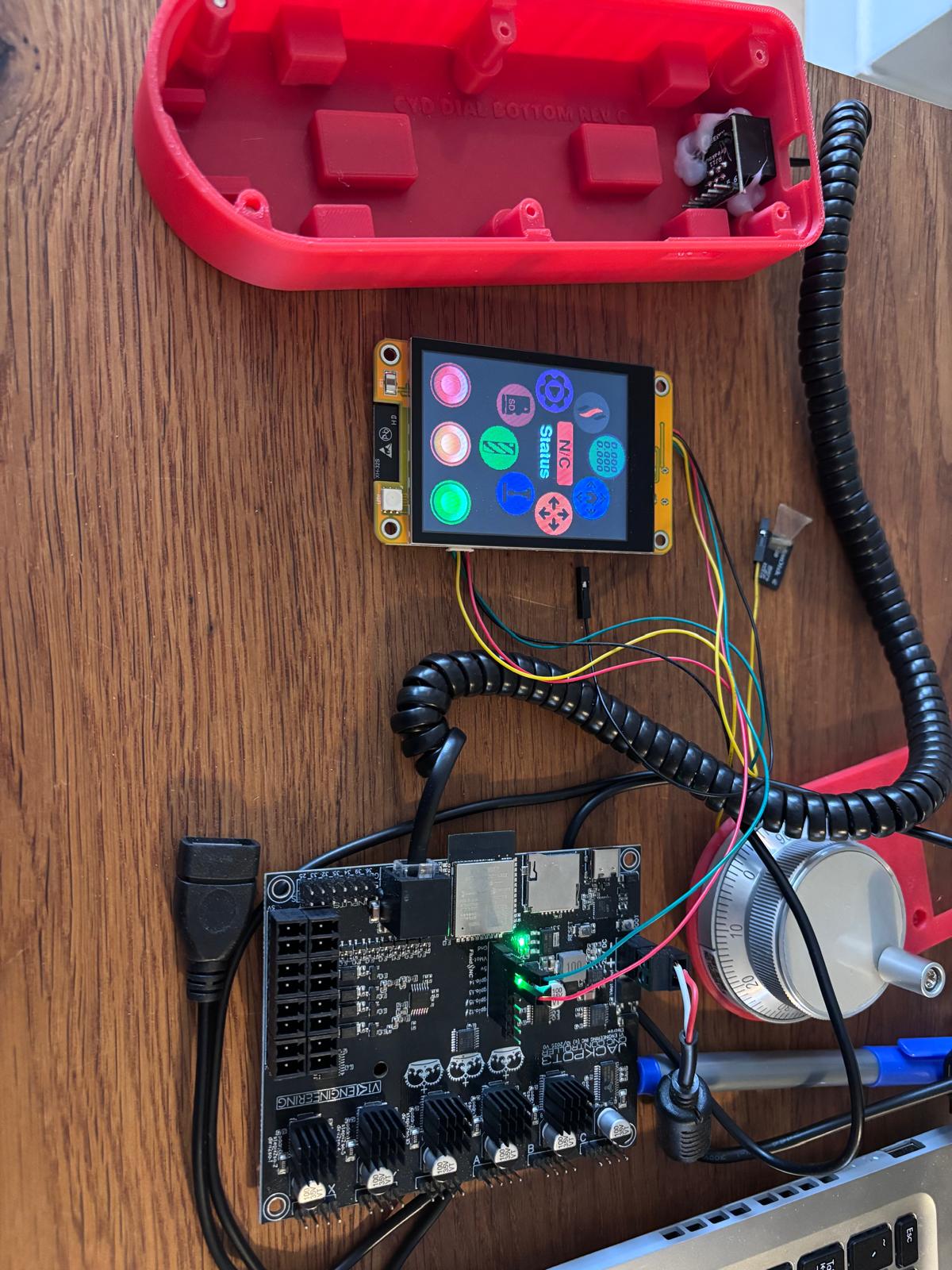
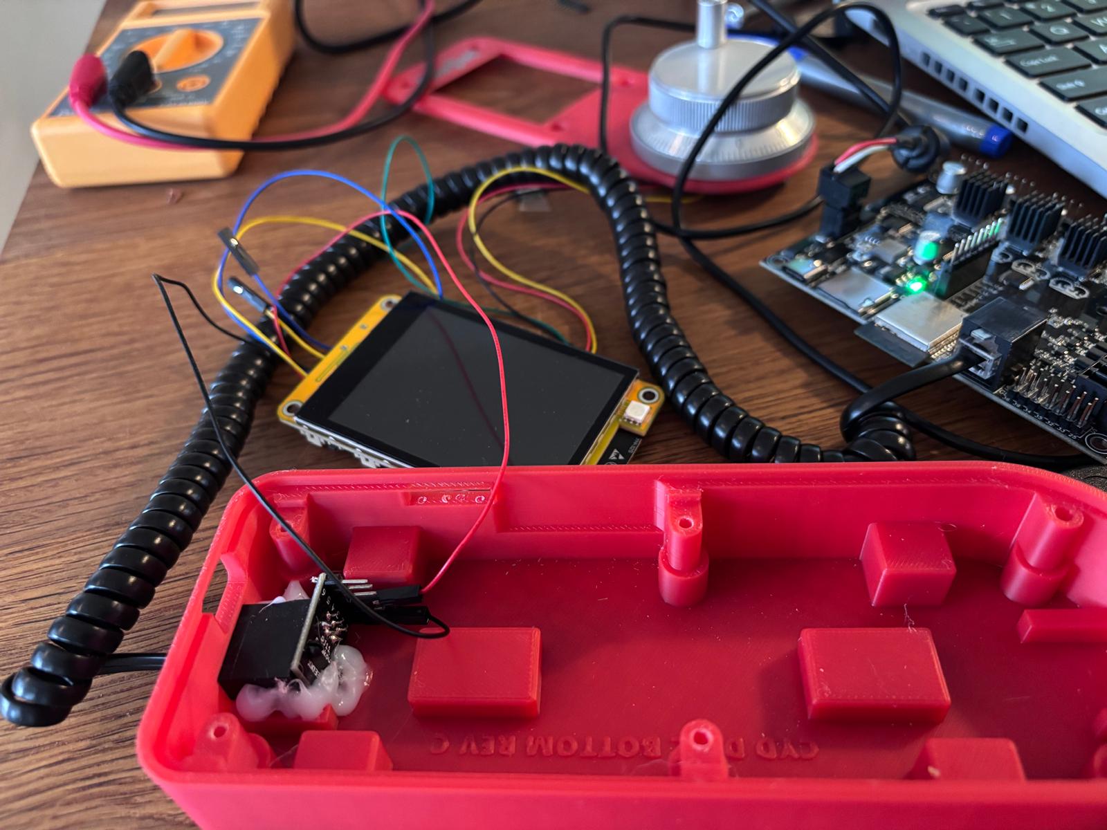
The good thing is the CYD is still working. I connected the gnd and V5 of the CYD to the gnd and v5 of the pins of the expansion module, and it booted up normally.
Next I did some continuity and Volt measurements with my multimeter.
All connections are still working. When I power up the Jackpot I have 4.9 volt at the RJ11 connector of the pendant!
However if i connect the CYD to the rj11 of the pendant the CYD will still not boot up. I measured the voltage and it is only 4.5V. Could this be the reason it does not boot?
When I connect the same wires to the jacpot 5v directly I get 4.9V at the CYD and it does boot.
I try switching the wires but keep getting the same result. So in the last step from the pendant RJ11 to the CYD I have a drop of 0,5V.
Hmmm, there is not much in between the 5V module output and the 5V pendant output. Does your coiled wire have a lot of resistance?
Is it still 4.5 at the end of the coil without the pendant plugged in? What is the voltage on the bottom of the board at the pendant plug 5v soldered pin?
I can’t pretend I am a fan of the pendant but it should 100% work.
I have 4,5 volt on the CYD board through the coiled cable, and 4,9 volt through the coiled cable without the CYD attached. Swapping the wires from the pendant to the CYD does not help.
This is begging for a pre-made kit. Using 5V for CYDs isn’t really the right approach. Picking off VMOT with a DCDC converter is better all around. This is one plus for the M5 Stack- it can accept VMOT directly as its power supply supports higer voltages.
Said differently, the CYD not having a wide input range power supply is rather daft. It’s designed for battery power and USB inlet/chaging. A requirements/design failure in my opinion if trying to use it for a long-cable tethered pendant.
When the CYD is not connected I have 4.9v at the end of the cable.
When the CYD is connected I have 4.5v at the end of the cable. I just measured and it is already 4.5 at the pendant RJ11 connector. It still is 4.9 on the Jackpot, so before the cable.
I’m happy that atleast as far as I know now i did not fry anything.
Length wise, the coiled cable I now use is not that long, 3 meter, which would also be about the length of a non coiled cable running through the gantry and drag chain. I was planning to add a connector in the table that is connected to the jackpot with a normal cable. And then connect the pendant with a coiled cable to the connector
These are the ones I’ve been testing with. I"m not ready to make this a recommendation because I don’t have any significant runtime on them.
The converters don’t need to be expensive, and as you note there is plenty of room in the original or @vicious1 low-profile enclosures to fit it. $9 for a 10-pack of them.
I was not keen on adding the port in the first place. It really sounds like I need to remove it. If anything save a bit per board. Or only recommend the M5 dials since they are 12V.
I can not recommend enough just to use the wireless webui, it is amazing these days and Mike and Jason have made awesome changes and plugins. Running that cable bundled with the steppers endstop and router power does not sound like a great idea. Those pendants are not exactly robust.
I’m not sure. The CYD implementation is most of the issue with this. My M5 stack pendants on the JP3 test setup have been rock solid.
I’ve been on the fence for a while and have previously noted that my recommendation is going to be that a builder just suck it up and spend the money for the buck converter if they really want a CYD.
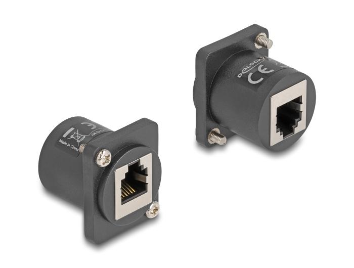
The RJ12 / 6P6C connector is Bart’s standard, but I’m not sure I like it.
How hard is it to do a version that has the footprint for the connector but not have it populated or soldered?
I’m really liking the development of the wireless pendants, but I do understand why sometimes you just want to have a tethered pendant.
Edit:
We talked about that in the Jackpot V2/V3 beta period.
I think the issue here is IR drop in the cable, not dropout in the regulator. It would be an interesting test, though.
I need to go back and check the Airedale expander, to see if it needs 5V. That’s another key benefit to having that port on the Jackpot even though few builders are using one at this point.
I have used a CYD pendant for a long time now. I use it on the original JP1 (LR4), JP2 and the JP3 (MPCNC). I have never had any problem with it working on any of them. I use the RJ12 6P6C cable that Bart recommends in the wiki. I also use the CYD capacitive display.
I just tested with a normal not coiled cable and it is booting up fine. I guess the coiled cable is of a low quality. Thanks for your help every one. I now need to connect the board back to the cnc and see if it also actually works with jogging etc!
Do you think running the cable together with the power cable will lead to interference issues?
Also I did not mean to stir up the debate on the use of a pendant or not. Personally I don’t like pulling out my phone to controll the cnc for a couple of reasons:
I find controlling it with a touch screen is not ideal. I really have to carefully press buttons, as you can easily press the wrong one.
half of the time the screen is zooming in
I have to scroll a lot. Which also causes the buttons to be on another place each time. So there is no real learning of which button is where on the screen.
I also find myself with an almost emty battery sometimes.
I want to use my phone for other things while the cnc is running
I think I would much rather have a dedicated device, not depending on batteries. So the pendant looked like a cool and easy solution. Plus I also like to build it.
I will definately also try out the plugins of Mike and Jason.
I use my M5 pendant almost exclusively. I really like having a couple physical buttons and a dial. That lets me watch my tool and manipulate the controls while jogging without looking away from the tool. Glad you got your pendant sorted.
I installed the jackpot back in the cnc and the pendant is working! (For now without the buck converter) I’ll keep it this way, when I have issues I can always try to add this. For now I will also stick with the flat cable. If in the future I run into an old free coiled telephone cable I might retry that.
Side note here, when I was about 10, I found out both that the phone cord had more wires in it than we used and that the camcorder my buddy had plugged into the TV used that many wires to show the picture.
So I rigged up his camcorder to play into the phone wires, I went home and wired my phone into the TV and had him try to call me and make a video call. Luckily it did not pop the TV input, but it also did not work, I was pretty bummed. I thought I invented home video calling.