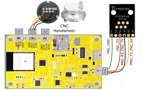
Today I tried to connect a CYD pendant to the Jackpot3. Unfortunately I cannot get it working.
While the board was on, I tried to plug in the RJ12 connector. The other end of the cable was not even connected to the pendant. As soon as i touched the RJ11 on the board with the connector of the cable I got some small sparks and the board crashed. When I unplugged the connector again the board would reboot. With the cable connected it does not.
As soon as I insert the connector again it crashes every time. Is the board faulty? Or is there any other cause?
It sounds like you actually have a bad cable, nothing should happen with a cable and nothing plugged into it. You can test with a continuity test on your cable, but we did our best to protect that port but a direct short between two random pins in out of our abilities.
Ok learned that the hard way! My assumption was that this would not be a problem for the connectors. I tested the cable and channel 1 and 2 were not properly connected.
Anyway, i used another cable, and the board does boot now with the cable inserted. However the pendant does nothing. (it does boot up when connected through usb on the computer).
I did comment out the Pentdant part in the config file:
2 I did not connect the RJ11 in the pendant correct to the CYD
3 The cable now used is a 4 wire cable in channels 1,3,4,5 (confirmed by the cable tester). This is exactly how it is explained in the tutorial. Or is this incorrect for the jackpot3?
4 the config file is incorrect
I will try to test 2 with a multimeter, but I’m afraid I fried the connector on the jackpot3…
I haven’t implemented the jackpot boards I bough a while ago yet, so am not versed in the configuration steps. Does putting a # in front of Pendant disable the whole section, or is the first line just a human-readable label?
The first cable was a 6 wire cable. Second cable is a 4 wire cable. But 2 of the 6 pins are not used (number 2 and 6). So a 4 wire cable should also be possible if connected to the correct pins (in my opinion)..
Can you explain why all 6 wires are needed? pin 2 and 6 are not connected to anything on the board. Or am I missing something?
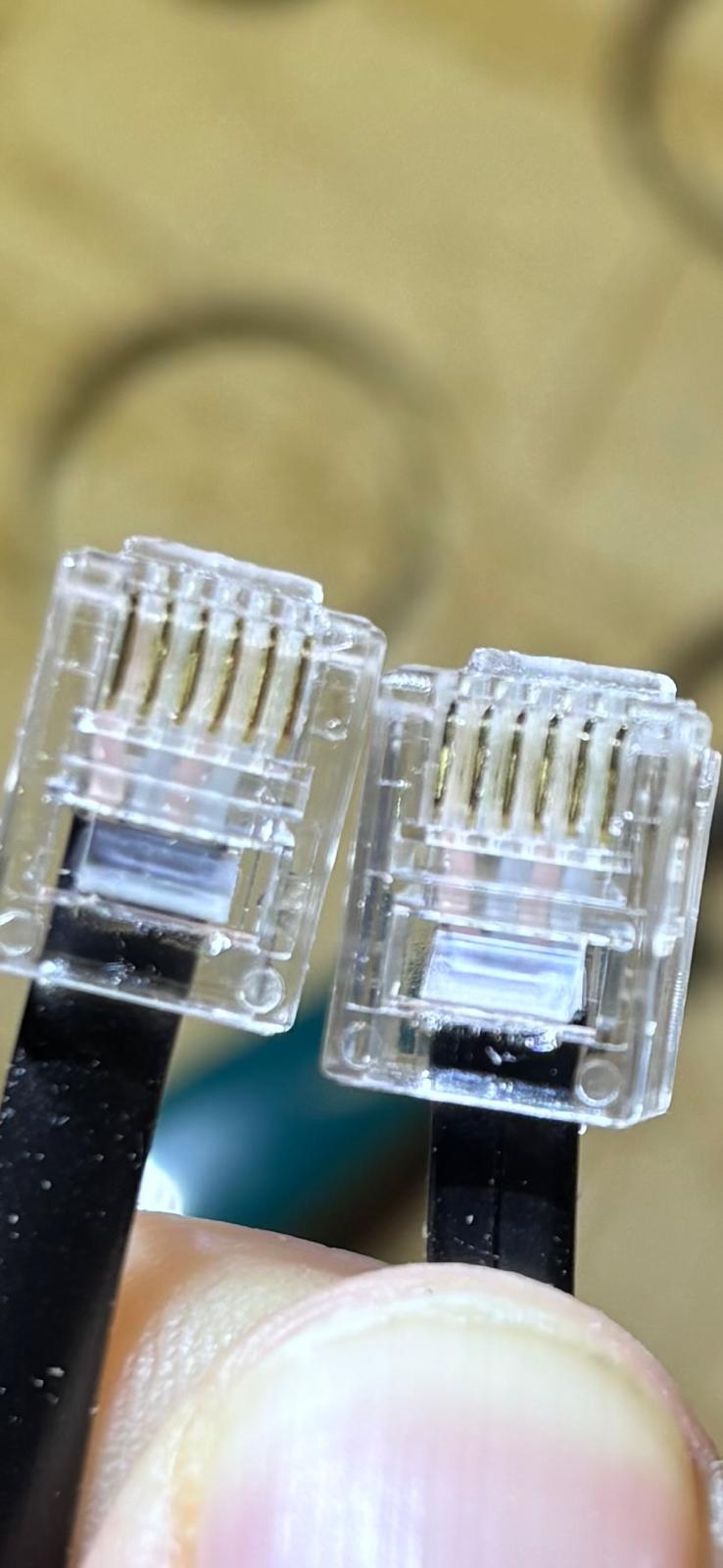
I have crimped the RJ12 connectors (with 6 pins) myself on the 4 wire cable to channel 1,3,4,5. They are straight and not crossed. I tested the wire and channel 1,3,4,5 are working.
That’s right.
The cable must be an RJ12, 6 wire, non-flipped cable. A flipped cable might destroy pendant or jackpot.
I’m decidedly a skeptic of using 5V board power for this. My CYDs are getting modified to install an under $10 DCDC converter to take VMOT down to 5V locally in the CYD.
Using Jackpot regulated 5V works, but it’s marginal.
Because pin 1 is ground. 4-wire cables don’t connect to pin 1 as an RJ11 starts offset from RJ12 pins (4 wire vs 6 wire connector)
Ok, I think I was not clear. I have a 4 wire cable. I cut of the RJ11 connector and crimped a new 6 pin RJ12 connector to the cable. With the wires in slot 1,3,4 and 5.
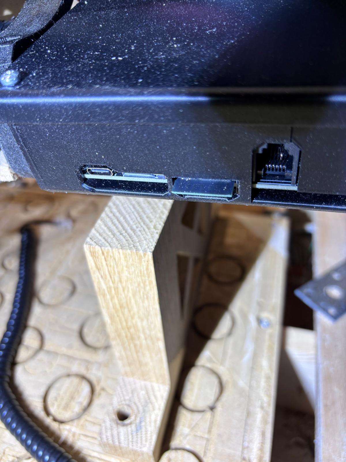
You custom crimped your own 4-wire cable into an RJ12 connector? I think I want to see pictures of both ends at this point, of the individual terminations at each end of the cable and the connectors looking into the jackpot and the CYD.
The other reason to not do this is the RJ11 connector can bend the pins in an RJ12 and if you bend or short those there’s another way to damage things.
yes, I custom made it (because i wanted a coiled up wire, which are usualy 4 wires). I tested the cable with a cable tester, confirming the connection is continous for channel 1,3,4 and 5. So no wires are switch or crossed. I cannot take pictures right now, I will have a look again tomorrow. I will also inspect the RJ11 on the jackpot for visual damage.
Good plan. If you can custom crimp your own RJ11, you’re mostly there to custom crimp an RJ12.
I understand wanting a coiled cable. They are much nicer to move around with (right up until they end up a giant coiled cable knot.)
I’m still going to continue encouraging users to build their own CYDs up with DCDC converters. I should update my own build conversion so I can share details here in the forums.
Ok, I’m maybe a bit confused with the terminology between RJ11 and RJ12. From what I can find the RJ11 conector has 4 or 6 pins. and can be connected with RJ11 plugs (4pins) or RJ12 plugs (6 pins).
So I custom crimped RJ12 plugs on a 4 wire cable, connecting channel 1,3,4 and 5.
I was also able to visualy inspect the RJ11 connector on the Jackpot3 and pin 2 (second from right), does seem affected. There is a little spot on the pin, and the pin is a bit bended downwards. It defenitely took a shock. However this is pin 2, which is not used. Not sure what it is connect to on the board though. I will try if I can get my hands on a 6 wire straight cable, but not sure if this will make any difference.
That’s not good. Pin 2 is VMOT. So if it touched any other pin or connector it fried it. I know from experience. I was testing a different RJ11 connector and accidentally touched pin 2. I fried my Jackpot 1. It sounds like the built in RJ11 connector saved your JP3, but may have fried something on the CYD.
The pendant was not connected when the initial shorting happened. However I might have connected it with the same faulty cable and the jackpot at a later moment. Not sure anymore. The CYD still works when connected to usb c.
if I want to test the CYD, can I just connect the screen to a 5v and ground pin, to test if it boots? Or do you need the rx and tx too?