Hey all… I’ve spent the day trying to wrap my head around the complete pain in the ass known as TMC2209 UART and the TinyBee V1.0. I wasn’t able to find a whole lot on it, but what I did find wasn’t encouraging. I’m trying to help out a buddy build his first MPCNC, and these were the components we wound up with. To boil a whole lot of playing around and tinkering with things down to something a wee bit smaller… Here’s what I found.
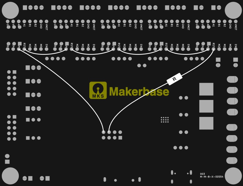
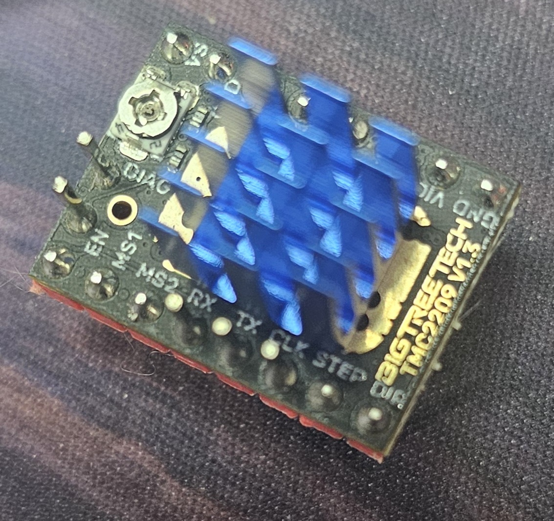
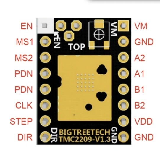
I’m not an electronics guru by any stretch, but I like to think I’ve got a few brain cells to run together. If anyone had noticed this, no one has posted it. On the FluidNC wiki page regarding the TinyBee, specifically where it covers mods to be done for UART, there is a rendering of the bottom of the board, showing where to daisy chain the GPIO16/17 wires. I followed all of this, gotout the meter to make sure no bridges or bad joints. Everything looked good. No UART communication when booted. My questoin/issue comes with… why is the CLK pin on the driver involved in this at all?? The 3rd pin over on each socket is the CLK pin on the BTT TMC2209 V1.3 drivers. On the bottom of the board, it’s simply labeled at “P”. I’ve included images of the rendering and the driver. Am I missing something, or is that wiring mod just wrong? Normally a TX line runs to RX and vice versa… never seen one go to CLK! I’m still working on it and where the wires should go, but was thinking maybe I stumbled across a reason so many people have issues with this board with these drivers in UART mode.
You haven’t posted high resolution pictures of your as-modified tinybee, nor of your modified TMC drivers.
Did you heed their warning?
WARNING: depending on the drivers you are using, you can destroy your board if you don not set the third DIP switch on every driver to OFF
At first glance at the FluidNC wiki, I don’t see where CLK is involved at all…
For reference if others want to take a look, I’m including it below since you didn’t link it.
Just to say it: You’ve spent more of your time on trying to modify a cheap board than buying one of Bart’s or Ryan’s boards that come out of the box purpose built for these machines.
Guys, thanks for the input. Maker Jim, you sir, are spot on. This board wasn’t mine, I have a Jackpot 2 in my Primo. I gave my Burley to my buddy and recommended he pickup a Jackpot and I’d come and get it hooked up and going. The combo of the TinyBee and TMC2209s is just fine… in stand-alone. Setting the TinyBee up with 2209s in UART… well… To quote a line from the end of Loose Cannons, If I had to do it over again, “ I’d rather set my head on fire and have it put out with a sledgehammer!”
Supposedly there are a few people that have gotten it to work, but I am pretty damn sure that I’ve scoured everything short or classified mainframes at NSA and was not able to come up with anything solid. Seems like most things I have were rebutted a few posts later. So, I went back to the setup I had initially started the 3-day weekend with… 2209s in Stand-Alone mode. super simple, worked perfectly. I am a very tenacious bastard and absolutely hate to give up on a task, but I finally reached my breaking point. Reverted to Stand Alone, set microstepping to 16, set the Vref and boom, done. My buddy feels bad about it, but I learned a lot through the attempt. He’s considering picking up a Jackpot. I told him that is really the most logical choice, as well as being the most well supported option.
Anyway wants to update the thread and say thank you!