FluidNC and MKS TinyBee

Hey everyone,

Figure I would do a quick write-up to help anyone else that might be looking for this information. I wanted to make the switch to GRBL, but was having issues with the Rambo 1.4 board. I tried a few Fusion360 post-processors and everything would start off fine, then all of a sudden the cutting tool would fly off in the positive x-axis direction uncontrollably which essentially destroyed the workpiece.

I bought an MKS TinyBee along with 5 TMC2209 stepper drivers. I was able to flash FluidNC without any issues, and could connect wirelessly to the FluidNC web portal. The trouble came when trying to get the configuration file dialled in so that I could get the correct movement from the CNC, as well as use gSender which I have preferred for controlling my MPCNC. I didn’t have any luck with the sample config files, whether it was for the TMC2209 steppers, or specifically the example for the TinyBee.

A few notes that I only figured out after several days of trouble shooting, in the hopes that it will help others.

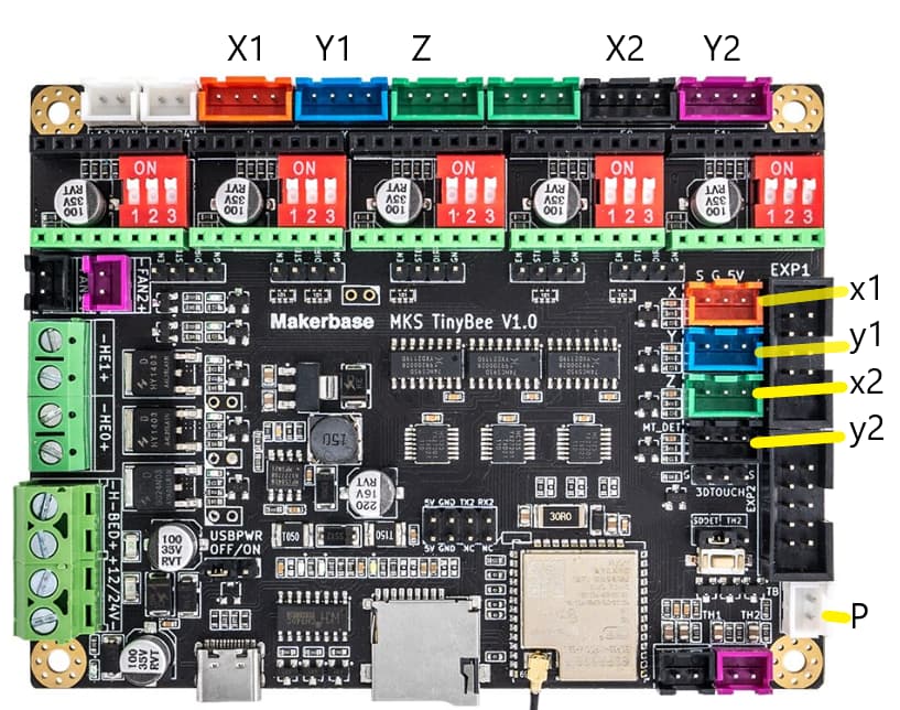
  1. When you look at the board diagram here you can see that there are six motor outputs: X, Y, Z1, Z2, E0, E1. What took me a while to realize is that Z1 and Z2 are run by a single stepper driver, meaning that you can drive two stepper motors with a single stepper driver, but you can’t control these independently. This is why the Z1 and Z2 plugs are both the same colour.

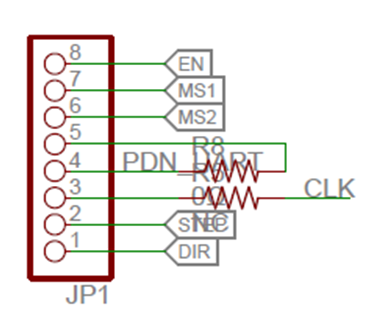
  2. I don’t understand the details behind all of this, however it seems that GPIO pins over and above around 32 or 36 (I can’t remember which one) have to be addressed through the I2SO system, instead of the GPIO referencing. The following are the I2SO pins to use for each motor port:

X Disable Pin: I2SO.0
X Step Pin: I2SO.1
X Direction Pin: I2SO.2

Y Disable Pin: I2SO.3
Y Step Pin: I2SO.4
Y Direction Pin: I2SO.5

Z1 and Z2 Disable Pin: I2SO.6
Z1 and Z2 Step Pin: I2SO.7
Z1 and Z2 Direction Pin: I2SO.8

E0 Disable Pin: I2SO.9
E0 Step Pin: I2SO.10
E0 Direction Pin: I2SO.11

E1 Disable Pin: I2SO.12
E1 Step Pin: I2SO.13
E1 Direction Pin: I2SO.14

Other important pins required if you’re using dual endstops for the auto squaring feature:

X Endstop: GPIO.33
Y Endstop: GPIO.32
Z Endstop: GPIO.22
MT_DET: GPIO.35

The way I have my MPCNC physically wired is as follows:

X0 Stepper: Wired to the X-Motor plug.
X1 Stepper: Wired to the Y-Motor plug.
Y0 Stepper: Wired to the Z1-Motor plug.
Y1 Stepper: Wired to the E0-Motor plug.
Z Stepper: Wired to the E1-Motor plug.

X0 Limit: Wired to the X end stop plug S and G pins.
X1 Limit: Wired to the Z end stop plug S and G pins.
Y0 Limit: Wired to the Y end stop plug S and G pins.
Y1 Limit: Wired to the MT_DET plug S and G pins.

I’ll add my configuration file at the bottom. Again, this is using TMC2209 stepper drivers (5 of them). I am able to auto-square in both the X and Y axes. I haven’t tried implementing a Z zeroing tool, however I would imagine if you wired it up to the 3D Touch plug and used GPIO.2 it should work.

board: MKS TinyBee V1.0_001
name: MPCNC

kinematics:
  Cartesian:

stepping:
  engine: I2S_STATIC
  idle_ms: 255
  pulse_us: 4
  dir_delay_us: 1
  disable_delay_us: 0

axes:
  x:
    # X
    steps_per_mm: 100.000
    max_rate_mm_per_min: 2000.000
    acceleration_mm_per_sec2: 500.000
    max_travel_mm: 325.000
    soft_limits: true
    homing:
      cycle: 0
      positive_direction: false
      mpos_mm: 0.000
      feed_mm_per_min: 300.000
      seek_mm_per_min: 5000.000
      settle_ms: 500
      seek_scaler: 1.100
      feed_scaler: 1.100

    motor0:
      limit_neg_pin: gpio.33
      hard_limits: true
      pulloff_mm: 2.000
      stepstick:
        step_pin: I2SO.1
        direction_pin: I2SO.2
        disable_pin: I2SO.0

    motor1:
      limit_neg_pin: gpio.22
      hard_limits: true
      pulloff_mm: 2.000
      stepstick:
        step_pin: I2SO.4
        direction_pin: I2SO.5
        disable_pin: I2SO.3

  y:
    # Y
    steps_per_mm: 100.000
    max_rate_mm_per_min: 2000.000
    acceleration_mm_per_sec2: 500.000
    max_travel_mm: 220.000
    soft_limits: true
    homing:
      cycle: 1
      positive_direction: false
      mpos_mm: 0.000
      feed_mm_per_min: 300.000
      seek_mm_per_min: 5000.000
      settle_ms: 500
      seek_scaler: 1.100
      feed_scaler: 1.100

    motor0:
      limit_neg_pin: gpio.32
      hard_limits: true
      pulloff_mm: 2.000
      stepstick:
        step_pin: I2SO.7
        direction_pin: I2SO.8
        disable_pin: I2SO.6

    motor1:
      limit_neg_pin: gpio.35
      hard_limits: true
      pulloff_mm: 2.000
      stepstick:
        step_pin: I2SO.10
        direction_pin: I2SO.11
        disable_pin: I2SO.9

  z:
    # Z
    steps_per_mm: 1400.000
    max_rate_mm_per_min: 200.000
    acceleration_mm_per_sec2: 300.000
    max_travel_mm: 80.000
    soft_limits: false
    homing:
      cycle: 0
      positive_direction: false
      mpos_mm: 0.000
      feed_mm_per_min: 300.000
      seek_mm_per_min: 1000.000
      settle_ms: 500
      seek_scaler: 1.100
      feed_scaler: 1.100

    motor0:
      hard_limits: false
      pulloff_mm: 1.000
      stepstick:
        step_pin: I2SO.13
        direction_pin: I2SO.14
        disable_pin: I2SO.12

i2so:
  bck_pin: gpio.25
  data_pin: gpio.27
  ws_pin: gpio.26

spi:
  miso_pin: gpio.19
  mosi_pin: gpio.23
  sck_pin: gpio.18

sdcard:
  cs_pin: gpio.5
  card_detect_pin: NO_PIN

control:
  safety_door_pin: NO_PIN
  reset_pin: NO_PIN
  feed_hold_pin: NO_PIN
  cycle_start_pin: NO_PIN
  # EXP1 BTN_ENC
  macro0_pin: gpio.4:low:pu
  macro1_pin: NO_PIN
  macro2_pin: NO_PIN
  macro3_pin: NO_PIN

macros:
  startup_line0:
  startup_line1:
  macro0: $SD/Run=lasertest.gcode
  macro1: $SD/Run=home.gcode
  macro2:
  macro3:

coolant:
  flood_pin: NO_PIN
  mist_pin: NO_PIN
  delay_ms: 0

Laser:
  pwm_hz: 5000
  # EXP1 BTN_ENC
  output_pin: gpio.13
  # FAN1
  enable_pin: I2SO.16
  disable_with_s0: false
  s0_with_disable: false
  tool_num: 0
  speed_map: 0=0.000% 0=12.500% 1700=100.000%
# 135=0mA 270=5mA 400=10mA 700=16mA
user_outputs:
  analog0_pin: NO_PIN
  analog1_pin: NO_PIN
  analog2_pin: NO_PIN
  analog3_pin: NO_PIN
  analog0_hz: 5000
  analog1_hz: 5000
  analog2_hz: 5000
  analog3_hz: 5000
  digital0_pin: NO_PIN
  digital1_pin: NO_PIN
  digital2_pin: NO_PIN
  digital3_pin: NO_PIN

start:
  must_home: false

The Laser portion, coolant, macros, etc can probably all be deleted, I just didn’t bother trying to cut that out yet.

As for gSender, apparently FluidNC does not send a $$ command upon connecting like plain GRBL does. In order for gSender to be able to work:

  1. Connect to the board with gSender.
  2. Access the FluidNC web portal.
  3. Reset the firmware through the web portal (under the middle GRBL panel, red square logo with a turn over arrow.).
  4. gSender should now work allowing you to jog. You still have to use the web portal to home each axis for some reason, but you can load gCode files through gSender to visualize and run.
7 Likes

All useful info…thanks

The reason is there are not enough hardware GPIO pins available on the ESP32 for all the functions required.

From expressif -

With further expansions of the ESP32 chip family, more application scenarios with diverse demands are being introduced, including some that have more requirements on GPIO numbers. The subsequence release of ESP32-S2 and other products have included up to 43 GPIOs, which can greatly alleviate the problem of GPIO resource constraint. If this still could not meet your demand, you can also add GPIO expansion chips to ESP32 to have more GPIO resources, such as using the I2C-based GPIO expansion module MCP23017, which can expand 16 GPIO ports per module and mount up to 8 expansion modules simultaneously thus expanding additional 128 GPIO ports totally.

I don’t see any port expander IC’s on my Tinybee but I do see three shift registers so I assume MKS achieve the same functionality as a port expander, just with cheaper IC’s :slight_smile:

3 Likes

Thank you for taking the time to put this together and post it.

relytjames just wondering if you have any feedback on FluidNC and/or this board.

Finally got around to giving this board a try and so far it has passed all the checks and successfully made some cuts on my Primo. A bit more tuning to go, but overall I think this is a great option. I’ve got the probe working using the TB input (with the help from some folks at FluidNC).

Config is mostly based on what @ relytjames has above and some things taken from fluidnc wiki.

board: MKS TinyBee V1.0 XXYYZ
name: MPCNC-PRIMO

kinematics:
  Cartesian:

i2so:
  bck_pin: gpio.25
  data_pin: gpio.27
  ws_pin: gpio.26

spi:
  miso_pin: gpio.19
  mosi_pin: gpio.23
  sck_pin: gpio.18

sdcard:
  cs_pin: gpio.5
  card_detect_pin: NO_PIN

stepping:
  engine: I2S_STATIC
  idle_ms: 255
  pulse_us: 4
  dir_delay_us: 1
  disable_delay_us: 2

axes:
  x:
    steps_per_mm: 100.000
    max_rate_mm_per_min: 8000.000
    acceleration_mm_per_sec2: 80.000
    max_travel_mm: 600.000
    soft_limits: true
    homing:
      cycle: 0
      positive_direction: false
      mpos_mm: 0.000
      feed_mm_per_min: 300.000
      seek_mm_per_min: 1500.000
      settle_ms: 500
      seek_scaler: 1.100
      feed_scaler: 1.100

    motor0:
      limit_neg_pin: gpio.33:high
      hard_limits: true
      pulloff_mm: 4.000
      stepstick:
        step_pin: I2SO.1
        direction_pin: I2SO.2
        disable_pin: I2SO.0

    # use E0 driver for 2nd X axis motor
    motor1:
      limit_neg_pin: gpio.22:high
      hard_limits: true
      pulloff_mm: 4.000
      stepstick:
        step_pin: I2SO.10
        direction_pin: I2SO.11
        disable_pin: I2SO.9

  y:
    steps_per_mm: 100.000
    max_rate_mm_per_min: 8000.000
    acceleration_mm_per_sec2: 70.000
    max_travel_mm: 440.000
    soft_limits: true
    homing:
      cycle: 0
      positive_direction: false
      mpos_mm: 0.000
      feed_mm_per_min: 300.000
      seek_mm_per_min: 1500.000
      settle_ms: 500
      seek_scaler: 1.100
      feed_scaler: 1.100

    motor0:
      limit_neg_pin: gpio.32:high
      hard_limits: true
      pulloff_mm: 4.000
      stepstick:
        step_pin: I2SO.4
        direction_pin: I2SO.5
        disable_pin: I2SO.3

    # use E1 driver for 2nd Y axis motor
    motor1:
      limit_neg_pin: gpio.35:high
      hard_limits: true
      pulloff_mm: 4.000
      stepstick:
        step_pin: I2SO.13
        direction_pin: I2SO.14
        disable_pin: I2SO.12

  z:
    steps_per_mm: 400.000
    max_rate_mm_per_min: 8000.000
    acceleration_mm_per_sec2: 60.000
    max_travel_mm: 80.000
    soft_limits: false
    homing:
      cycle: 0
      positive_direction: false
      mpos_mm: 0.000
      feed_mm_per_min: 300.000
      seek_mm_per_min: 500.000
      settle_ms: 500
      seek_scaler: 1.100
      feed_scaler: 1.100

    motor0:
      pulloff_mm: 3.000
      stepstick:
        step_pin: I2SO.7
        direction_pin: I2SO.8
        disable_pin: I2SO.6

relay:
  direction_pin: NO_PIN
  output_pin: i2so.17
  enable_pin: NO_PIN
  disable_with_s0: false
  s0_with_disable: true
  spinup_ms: 0
  spindown_ms: 0
  tool_num: 0
  speed_map: 0=0.000% 0=100.000% 1=100.000%
  off_on_alarm: false

probe:
  # this is the TB input
  pin: gpio.39:low

control:
  safety_door_pin: NO_PIN
  reset_pin: NO_PIN
  feed_hold_pin: NO_PIN
  cycle_start_pin: NO_PIN
  macro0_pin: NO_PIN
  macro1_pin: NO_PIN
  macro2_pin: NO_PIN
  macro3_pin: NO_PIN

user_outputs:
  analog0_pin: NO_PIN
  analog1_pin: NO_PIN
  analog2_pin: NO_PIN
  analog3_pin: NO_PIN
  analog0_hz: 5000
  analog1_hz: 5000
  analog2_hz: 5000
  analog3_hz: 5000
  digital0_pin: NO_PIN
  digital1_pin: NO_PIN
  digital2_pin: NO_PIN
  digital3_pin: NO_PIN

start:
  must_home: false

Motors are X1, Y1, X2, Y2, Z.
Limit switches are x1, y1, x2, y2 and use the S and G pins (left two pins).
P is the z probe.

The spindle relay is still untested.

1 Like

Good info :+1: The spindle relay looks like it should work fine off HE0 and an opto-isolated relay board

Hi quick question, I am new to this (sorry), but I am trying to figure out the Yamal code that you posted. I can not find what stepsticks that you used on it, I have 5 of the 2209 drivers but have no idea how to add them to your file? Any help would greatly appreciated. Thanks a lot!!!

The config I’ve posted is also for the TMC2209 stepstick (as well as relytjames). If you were to use something else I believe the steps_per_mm would need to be adjusted and possibly some of the attributes under stepstick for each motor*.

Thank you so much for all of your hard work, this helps me a lot!!!

There is a wiki on using FluidNC, it is very good. There is a section on the type of stepstick driver here, it gives examples of the code needed.

You can simply use a 2209 in legacy mode or UART mode if you want to configure the settings on the fly

I was able to to further test this out and can confirm the spindle relay works.

Also added a fan on i2so.19

#fan
user_outputs:
  digital0_pin: i2so.19

I played around with a 4wire fan too, but still haven’t got the pwm part worked out (as of now using this as a reference).

RONALD J MCKENZIE, one thing I should mention, the motor connections were not straight forward for me… I needed to plug X2 and Y2 in reversed/flipped of X1 and Y1, see EDIT below. I’m not sure why this is, but I’d be interested if anyone else runs into this.

EDIT: here’s how I’ve wired the motors so that each motor moves in unison with its twin…

UPDATE: taking a step back and looking at the mechanics of the machine, the two motors for each axis will need to turn in opposite directions. I’m coming from a RAMPS board where all motors were plugged in with the same orientation… so I’m thinking the RAMPS firmware must have been accounting for this in the background.

2 Likes