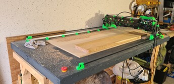
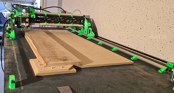
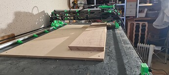
Right, so in those cases perhaps there are other options to achieve the same outcome.
With the cutting board, I assume you want to laminate the boards to make something like an end-grain cutting board and you’re going to cut it down further once laminated? Instead what about cutting it to the height first and then stacking those up to be glued so instead of gluing 2 huge boards and then cutting those down, you’re cutting each board down and gluing ~20 pieces of board? The LR is likely plenty flat enough to flatten a finished cutting board for use.
For the jewelry box: This is just to get the lid to sit flat with no gap? One option is to add a slight chamfer and make the gap a feature (that’s something I’ve seen four-eyes furniture and Pendulla studios do a few times, I think). Another option would be to do a specific flattening step with a sheet of ~80 grit sandpaper on a flat surface like a piece of glass or a chunk of MDF. I’d also think that the LR is likely still pretty flat over small distances, it’s really the long distances that you’re likely to see issues. If you’ve got a problem with the roughness that your bearing is riding over for a short distance you could always try to find a thin piece of steel or a steel ruler etc. for it to ride on just over 300mm or so to try out.
One thing I’ve found helpful in the past when I run into a problem like this is to brainstorm at least 2-3 other ways of solving the problem and then trying whatever seems interesting or suits what I have on hand.
It may be that the solution you come up with is only suitable for jewellery boxes or cutting boards but that’s fine, the next project can have a new solution that suits that specific set of needs.
Right, so there are situations where that wouldn’t be an issues, necessarily, but other situations where it would compound, like the cutting board glue up. I think the solution above is better but alternatively you could glue it up, slice the board into sections that are various widths, stack them together to see how well they fit and if they need more fettling then screwing some alignment blocks onto the table and then using the LR to thickness each one accurately would likely work.
Fundamentally, the machine issues can be separated into overall flatness and local surface roughness. With larger machines, it takes more effort to keep the deviations over the entire length small. That’s just a downside of large machines and why a remarkably cheap CNC router can have a working area of meters by meters but a manual milling machine that costs and weighs 10x as much has working areas in the low hundreds of mm, max.
If your issue is local roughness that can potentially be solved by fixing the surface in a small area. If your issue is flatness over the entire table, that can potentially be solved by working over smaller flatter sections and dividing work down accordingly. It really should be rare that you actually ‘need’ to flatten a huge surface to sub-mm precision. A 2m x 1m table that deviate by 1mm over 10mm will be noticeable, 1mm over 100mm might be, 1mm over 1m will absolutely not be and likely it’ll change by more than that through the seasons without careful attention or using a composite product etc.
I built mine with a tracksaw, so you should be able to do reasonably well with a rip jig. With the tracksaw I can easily cut to within the accuracy of a pencil line so straight-edge level of straightness in the cut with maybe 0.2-0.3mm parallelism over the length of the cut.
So the thing with sheet goods is that it provides stiffness and stability in 2 dimensions at the cost of flexibility in the 3rd. The torsion box needs to be built in such a way that it provides that stiffness/stability/accuracy in the 3rd dimension, Z. To do so, we use the same sheet goods but cut with a straight edge to support the surface. It’s vastly easier to cut straight lines than it is to flatten a surface.
There are common/standard ways to make a torsion box table, but that leads a lot of people to think of that being what a torsion box ‘is’, rather than what it’s doing and the fundamental goals/design purpose.
So, to support the tabletop in a way that allows it to take a lot of load and remain flat, we cut tall ribs out of sheet goods in a way that gives them a very straight edge. That straight edge that we cut becomes the reference for how flat the surface will be, given that the surface can flex in Z much more readily than the ribs can flex around their long sides.
I’m sure you’re already well aware of this, but to clarify it just in case: Imagine taking a 6x1 board and trying to bend it. It’ll bend readily around the short dimension but it’s way, way stronger when trying to bend in the long dimension. If you were to take 2 and screw them together to make a T shape, even if the top of the T was bent like a banana, the strength of the bottom of the T would win and the top would bend until it conformed to the straightness of the edge of the bottom. As long as we had made sure that edge was nice and straight then the T section would now be straight down its length. That’s also how we get to the ‘depth’ of the ribs. Deeper will be stiffer, to a point, so if we tried to do the same T structure with 2x1s it would be nowhere near as flat as with 6x1s etc. because the 2" wide edge will bend more under much less load than the 6" wide edge.
The fundamental thing here is making sure that there is an edge in place to provide support to resist any loads that will try to bend the surface. Typically the easiest way to do this would be a continuous rib down the entire length of the table but it absolutely doesn’t need to be. Imagine doing 2 ribs side by side that ran the entire length, that’d be plenty strong. Now imagine those 2 ribs only go 2/3 of the way each, so there’s 1/3 overlap in the middle. As long as those ribs are well fastened to the surface, the only way for that to bend at that point would be to bend both those ribs or to ‘twist’ the table. If you made those ribs go halfway each then that could be bad, as a load in the middle could bend along that ‘crease’ line and the bottoms of the ribs would pull away from each other (assuming there’s no bottom skin). There are a ton of ways to solve even that. We could add a cleat across the gap in those ribs fastened to the ribs such that they can’t pull away from each other. We could add another rib next to it that runs across the joint and gets fastened into the table top. We could some kind of woodworking joint to combine the ribs together (just glue, dowels, dovetails, mortice and tenon, finger joint), as long as it keeps the straight edge straight. Or we could add a skin to the bottom of the table which resists the bottoms of those ribs pulling apart. Each of those has different pros and cons, some like the cleats across the joint are super simple but will alignment before being fixed in place to make sure the surface stays flat. The extra long ribs with overlap use more material than they would otherwise so you have a heavier and more expensive table, but they’re super simple to assemble completely.
So assuming we’ve done one of those things, we’ve now got a big flat piece of material that’s our working surface and a bunch of parallel ribs under it running down the long dimension that are well fastened to it that stop it from bending under load. The table will be very stiff in the long dimension but still no stiffer in the short dimension. We can then do the same thing by adding ribs in the short dimension so stiffen things further. That’s a problem for us because we already have the long ribs in the way. There are a bunch of ways to solve that, one being cutting a lot of short ribs that go between the long ribs. The issue there is that the short ribs don’t do a lot by themselves, they need to be linked together such that they behave like a long rib. That can happen by affixing each short rib to the perpendicular long ribs, either by screwing through the ends, corner cleats or through the skins themselves.
Or, as you’ll have seen there, that approach has a few very long ribs and a ton of short rib sections. Alternatively that could be rotated 90 degrees and you have a moderate number of single piece ribs running along the short dimension of the table and then a truly enormous number of short rib sections for the long dimension. That’s probably a good way to go insane with assembly and spend a ton of money on fasteners, but with the right assembly process I think it’d go by pretty quickly.
There’s also the consideration of whether you have a skin on the bottom or not. The skin on the bottom adds a remarkable amount of strength so you can have a lighter/thinner table for the same strength because it acts like extra ribbing in both dimensions. On the other hand, it does mean you need the ribs to be at least somewhat accurate height. That can be mitigated by having the bottom skin be much thinner and more conformant, or by cutting the ribs in a way that’s inherently accurate height (table saw + fence, CNC), or by adjusting after the fact with shims, sanding, planing, etc. It doesn’t need to be flat, it just needs to be uniform enough that adding the bottom skin doesn’t put tension into the whole structure and pull it out of whack.
So all of that is a long way of saying that there a ton of approaches that could work and end up with a large, stiff torsion box table that don’t necessarily require any ability to work with pieces that are the dimension of the table. I quite like the approach shown in some of the parametric table threads where the ribs are all solid and are notched so they fit together nicely. I’d probably take that approach but cut the long ribs half as long and then cleat them together at the joint. Any out-of-flatness would be very much right in the middle of the table and obvious, which means it could probably be fixed by shimming.
That’d be an interesting thing to do as a ‘see if this works’, but I suspect it’d suffer from the same limitations as measuring everything and then adjusting the toolpaths, just that ones doing it once and committing it to hardware, the other is doing it every time in software. I’d sooner try to add an MDF runner and shim it to flat manually.
I dunno, it’s definitely an expensive way to get a table but dramatically cheaper than something that’s a realistic next step. I’d note that I also don’t think I would attempt this approach on something that’s the ‘next step up’ in terms of CNC capability, like an Aavid or whatever.
Nice, well you could always look at it from the perspective that getting something now will be awkward to use for 6 months and need lots of shuffling but will have space later. I use my Makita planer clamped to my Paulk smart bench and that works out well for me. I probably use it ~10-20 hours a year absolute maximum, so having it be able to be tucked away under a desk is best, even if it takes ~20 minutes to get it set up and ready to run.


