Improve LR3 flatness to plane boards

This is the LR4 built on “Guido the table”…

I belive building straight/level/parallel rails and then using those to flatten the cutting surface- whatever it is- that is the way to get great performance without going insane with perfectionism.

I know this well…
I can get wrapped in a do loop trying to achieve perfection. I have to tell myself all the time that perfection is the mortal enemy not only of good enough, but also of getting things done.

3 Likes

Very timely comment, Jim. I’ll try to add some actual data later today, but I’ve been working on flattening “Guido” the last couple of days, and at the moment, I have about a 700mm x 900mm area that is flat to within (get this!) about +/- 0.5mm. And the MDF spoilboard will be on top of this.

The remainder of the work area on Guido (~1050mm x 1600mm) is going to need to be supplemented at the extremes because the falloff is so severe. BUT, with this much progress, the machine is very usable!

3 Likes

Thanks Dave, I’ll take a look! I’ll have to read through to confirm, but this sounds like where my mind was headed when starting this thread. I appreciate you pointing me to this thread and glad to hear it worked great for you!

This is the part I don’t know how to do…

So true.

I love it Dave. One big question remains for me, how do you ensure the supplemental rails are accurately parallel to each other (when veiwed from the side), to avoid twist?

Winding sticks or a level. I like the levelling approach. If both sides are level, they are inherently parallel in the only dimension we really care about. On the other hand, that does mean you first need to get the rail level. The winding sticks approach means you can get them parallel in that dimension without needing them to be level.

I believe most of the responses you’re getting here are still talking about getting something flat to within acceptable tolerances for use with relatively flexible sheet materials, so maybe a few mm over the distance.

If you’re not sure where to start, I would just try to get both sides level, check them with a couple of bits of wood used as winding sticks and then run a surfacing pass. You can easily check the result with a straight edge and feeler gauge to let you know how close you got.

1 Like

Totally. I guess I just assumed the accuracy of a level wouldnt be close enough. So it would have to be better than 0.5mm over 1 meter, and arctan (0.5/1000) ~= 0.03deg. I figure even at this it would allow twice that in total error of difference at 1m, and proportionately more even at the ends since the rails are over 1m long.
After calculating that in degrees and then Googling to compare that with the expected accuracy of a spirit level, I found they actually meaure it in mm/m anyway :slight_smile:, and I’m reading 0.5 to 1mm is reasonable. Thats less precise than I want, but worth trying. I’m thinking I can get the most predictable reaults by running both rails as level as possible, then running the level perpendicular between the rails to check (before commiting) as the distance between the rails is less.

Wish I just had a super flat reference surface larger than my table to build on but can’t think of one. The levels seem worth a try and adding straight rails that I get as parallel as possible with spirit levels seems like still a big improvement over what I’ve got now.

Again, the assumption here is that the machine will be used with flexible sheet stock and that where more precision is needed, say for surface engraving with a V-bit, that a smaller area will be surfaced first to provide a relative reference.

If your table is stiff enough to hold its own weight, it’ll get pulled out of flat anyway. The way to a truly flat large table is a torsion box, as above. That will be as flat as you can cut a straight line.

I’d just go with getting it a bit flatter, verifying to yourself how flat it is and then using it from there. Give it a try and then fix any issues that actually crop up. :slight_smile:

I think I may have come off as not listening to what you were telling me earlier. Sorry about that. With the reference surface I meant that before remaking the table as a better torsion box design I could try to use a flat reference plane to mount supplemental rails very parallel - ie, place blocks under table flipped upside down and mount the rails to the sides of the table while they lay on the reference plane to keep them parallel.

Of course you’re right that building a better torsion box table will help minimize the rails going out of parallel so I may need to go there anyway.

I’m still convinced that I need to use the ideas and methods you pointed out earlier (like planing boards at target dimensions, etc) to accomplish my goals rather than try to force the machine to accurately plane long boards.

It’s completely possible to bootstrap a table with nothing but a spoilboard on a garage floor and a pair of rails made from MDF or similar cut to just wide enough to recieve the Y rail on one side and the YX plate feet on the other.

The table doesn’t have to be perfect, or even particularly good in order to start getting results you can then improve on with a final or intermediate table.

It’s actually pretty simple to line up these “outriggers”. Note that this is very different than if you were to try to use two rails on the LR–that’s an entirely different issue, and much more difficult.

I’ll try to describe this in words, but if I’m not successful, maybe I can prepare a couple of drawings.

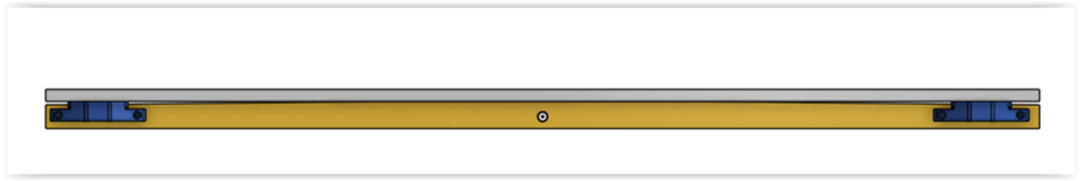
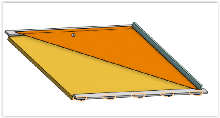
The first thing you need to do is to attach one of these outriggers to the EDGE (y-z face) of the table you plan to use and get it to be straight. You’ll want it’s (x-y) face to be approximately parallel to the TOP (x-y face) of your table but the exact alignment doesn’t matter. Once you have one end attached (but not extremely tight… it needs to be able to rotate a little bit in the y-z plane.) you can
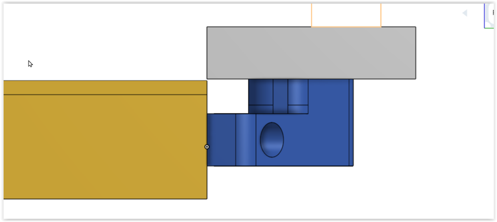
attach your level using clamps to this outrigger and carefully rotate in the y-z plane so that it’s at about the same angle as the table surface, and fasten the other end to the edge of the table. These fasteners should be very close to 90 degrees. The design that I showed is one such fastener, but the concept is pretty simple. However, I couldn’t find any inexpensive and rigid solutions which is why I 3D printed mine. You may want to add some more of these brackets while you have the level attached to prevent sagging. (I have 5 along the y-z edge of my 63" table.)

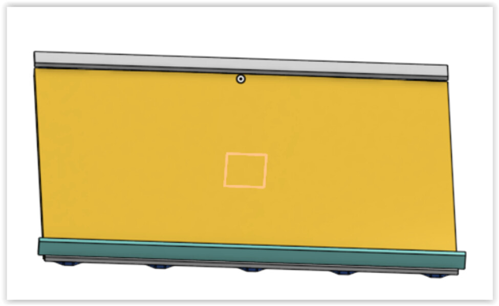
At this point, you will have one of your outriggers attached to the y-z edge of your table, with its x-y face more or less parallel to the table top, depending on how non-flat the table is. (Note that there is no reason that the two surfaces need to be coplanar, but you won’t want your outrigger to be too much higher than the table ţop. (The LR needs to be able to drop down low enough to flatten the table.)

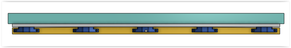
The rest of the process is pretty simple. You take the second ourigger and attach it to the opposite EDGE of the table. You will clamp a straightedge or second level to the face of that outrigger so it doesn’t sag.

Ideally, your right angle brackets will be adjustable in the z direction because you want to use your level ACROSS the outriggers at one end, and then the other end. Again, you don’t want the outrigger to overlap the face of your table top.

If you have followed this so far, you will wind up with the two outriggers with coplaner x-y faces, which is where you’ll mount the LR. They will also be fairly close to coplaner with your table, but being exact doesn’t matter since you can now use the LR to flatten the table. Also, the spacing between the two ouriggers is unimportant since the LR simply rides on one rail and the other side’s travel is determined by the gantry. It will run parallel to the fixed rail on the other outrigger.

One thing to note: this approach will make your table a few inches wider, which means the LR gantry will need to be longer in the X dimension. In my case, I actually trimmed about 1/2-3/4" off both faces because they weren’t perfectly flat and perpendicular to the table top and so that my LR would be able to ride on these outriggers.

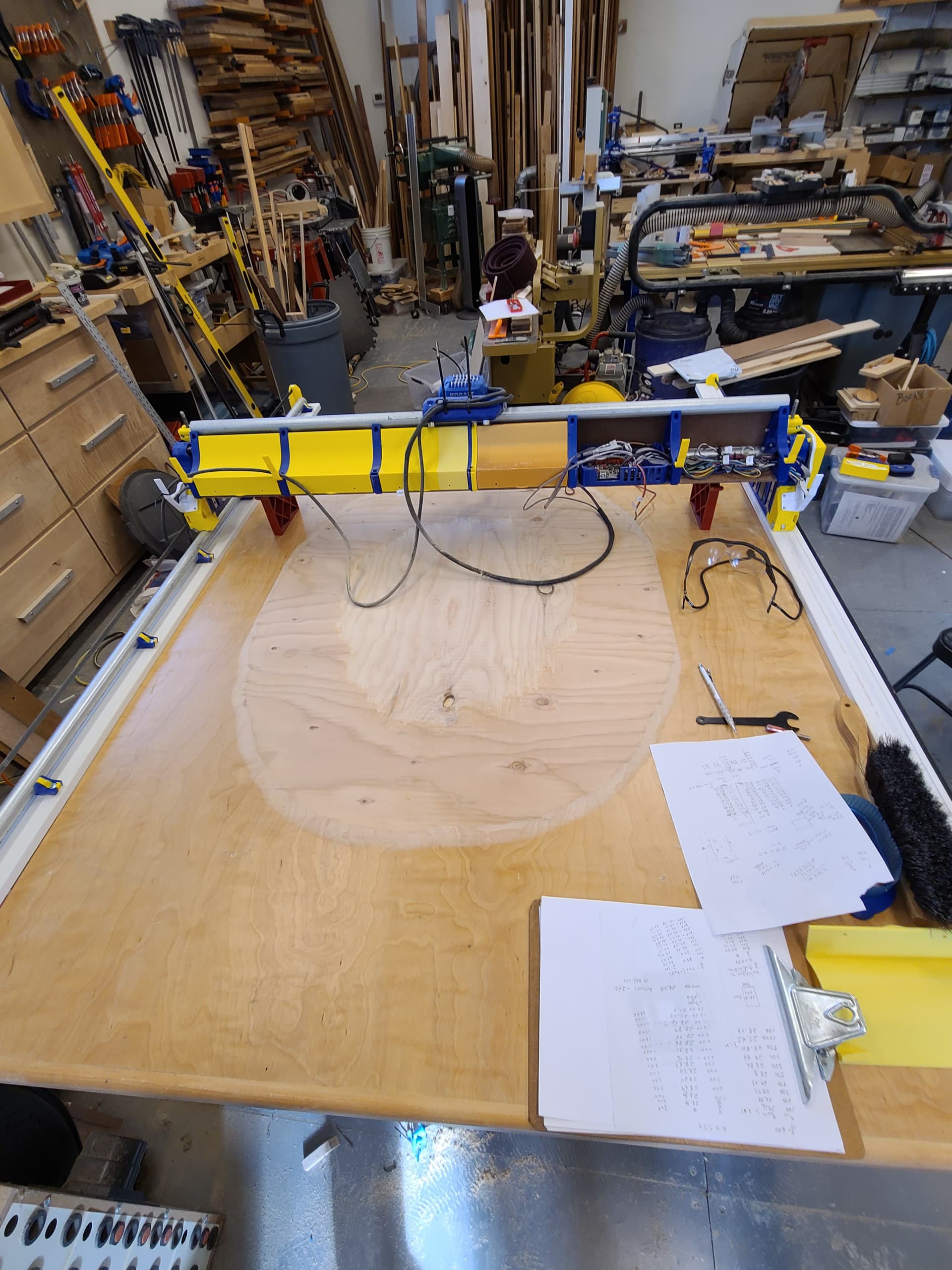
And, just for some “eye candy”, the photograph shows the first flattening efforts of my table (aka “Guido”) which had a substantial crown, about 3/8 inch center to edge. Now, the area in the center is about 700mm x 900mm and is flat to less than +/- 0.5mm across them entire area. This surface is plywood, so if you look closely you can see the boundary of the top layers due to the flattening.

Unfortunately, in my case, the crown is so severe that at the +/- y extremes, the drop off is still ~8mm so I’ll probably glue some 1/8" Masonite across the ends and then flatten that to the same height as the center area. The spoil board will be on top of this, and should in the end be quite flat.

2 Likes

Hey Dave, sorry for replying 2 weeks later. Somehow I missed the notification that you posted.

I was following up until this point. By ACROSS the outriggers do you mean the level goes from one outrigger to the other, ie perpendicular to the long dimension of the outriggers, and you used the level to determine height of the second outrigger at the extremes (Y min end and Y max end)? This makes sense. If a level is accurate to 0.5-1mm per m, I figure this should only allow ~2mm maximum “twist” from coplanar to the first outrigger, but maybe checking with the level run diagnally as well would likely improve it further I think? Anyway, I like it and think this is what I’ll do when I get my next dose of free time enough to implement this.

The way I am picturing this method the outriggers need to be at least slightly higher than the table surface at the extremes, correct? It does look like this is how yours is, maybe a cm higher or so?

Not sure I understand what you mean by this.

Super cool looking. It’s essentially a topographical map of the crown pre-flattening!

I’m thinking of making the outriggers by ripping them from MDF and gluing two MDF runners running the long direction in a rabbet (along the attached side) and groove (in the middle) to keep it straight and rigid. Sheet goods like MDF would be easier to work with and easier to source for me than steel angle iron or something. Do you think that would work?

Thanks!

Not a problem. It took me a while to try to formulate a response. Hope this helps.

That is correct. Essentially, the key idea is that three points in space define a plane. So, what you eventually want to do is to make sure that the surfaces of the two outriggers are in the same plane. By getting the first one attached and then attaching one end of the second one, you have defined the plane. So, the remaining step is to just rotate the unattached end of the second outrigger so that it’s in the same plane.

I have included some drawings below that will hopefully make this concept clear. It’s not clear that the diagonal measurement is needed if you have made sure that the second outrigger is as straight as possible by attaching a known straightedge.

[As a side note, I didn’t do this, but if one has a laser level on a tripod and could locate it so that it defined the plane above the non-flat table, it would be pretty easy to do this. My shop has an elevated floor made of 2’ x 2’ sections and we used the laser level to set the height of each plate. Ultimately, the floor is abou 1000 sq. ft. and it’s level to within 1/8" across the entire area.]

This is correct. You’ll need to be able to flatten the table relative to the outriggers. At the same time, the LR4 can only drop down a certain distance. If the outriggers are too high, you may not be able to flatten the entire table. Also, it’s nice to eventually have your spoilboard sit slightly higher than the outriggers so that you can flatten it a couple of times before replacing it. I am actually using a 1/2" straight bit with 1.25" cutting length to flatten my table. Even though it’s slower than a 1" diameter surfacing bit, it looks like I’ll be able to access almost the entire table for flattening.

Depending on how non-flat your table is, you may not be able to drop down far enough to flatten the entire surface. By mounting the outriggers on the edge you can set the height such that you will probably be able to do the whole thing.

Exactly. I had not actually realized how non-flat my table really is.

It should work. MDF with proper reinforcement to be straight is perfectly fine. My outriggers are actually MDF trim material that is precut to 2.5" and 3.5" I think. They are held straight by the 3D printer brackets so the unsupported spans are less than a foot. In my case, since they are actually longer than my table by about 10" on each end, I’ll need to add a cross support to maintain the rigidity. On the rail side, the rail actually does this, but on the belt only side, there is some sag at the ends.

And, now for those poor souls who have made their way through all this so far, here are some sketches that may help to illustrate this process.

  1. Table is not flat. It’s actually worse than this drawing suggests. Grey is the exact reference line, looking from the long edge.

2.Attach first outrigger using brackets at the ends. The exact placement is not extremely critical but it’s probably good to have the mounting brackets be approximately at the same height.

  1. End view of outrigger, bracket and table.

  2. Attach straightedge or level (green) to make sure outrigger is straight when additional brackets are attached.

  3. Now attach one end of second outrigger to the other side of the table. Note that the two ends of the first outrigger and this attachment point define the plane on which the LR4 will ride. You can use your level (green) ACROSS the table to set the attachment height of the second outrigger. The three vertices of the orange triangle indicate the work plane for the LR4.

  4. Now, you can use the level to set the other end attachment of the second outrigger by going across the table (second image below. You will also want to attach a straightedge to the second outrigger to make sure it is straight.

Hopefully, these sketches have clarified the procedure a little bit.

1 Like

Awesome! I’ve got to gather some materials (longer gantry rails) but can’t wait to upgrade my table this way. I’ve been meaning to purchase a laser level for some time - maybe this is the project I use as an excuse. Thanks again for all your time!

Good luck. Luckily, most folks will never have to deal with something this extreme. In my case, the choice was to either figure this out or scrap what is otherwise a very robust, solid table. For my smaller LR3, and smaller projects, I made it work by simply flattening the spoilboard or, in smaller pieces, the work piece itself.

In the current case for my LR4, the effort to achieve my 42" x 72" workspace will have made the effort worthwhile.

2 Likes