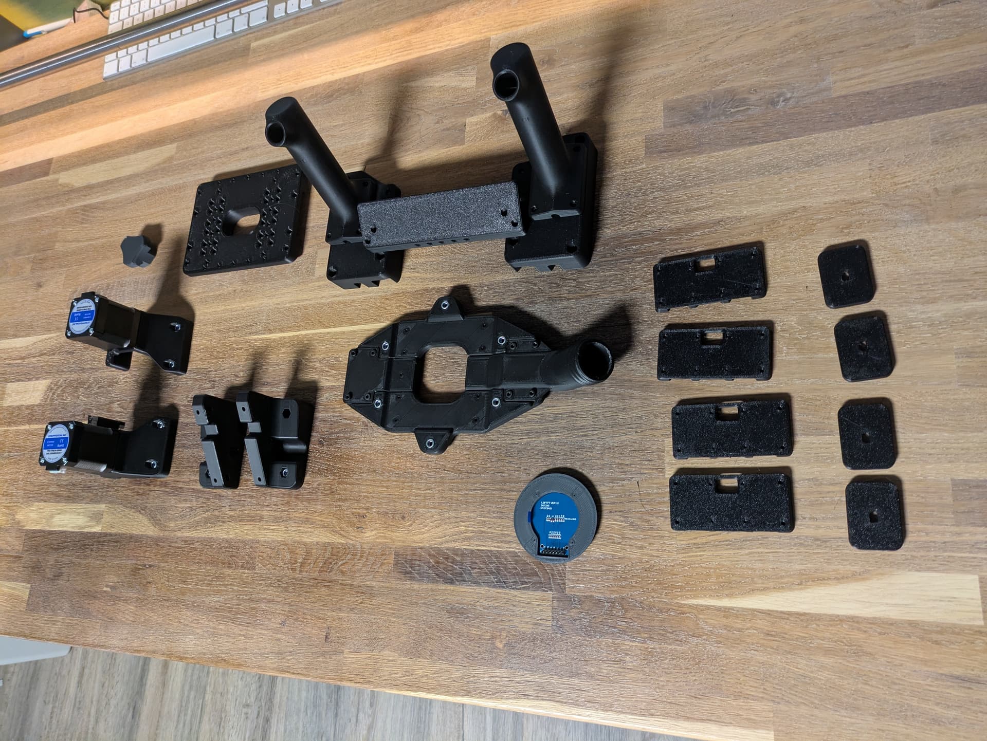
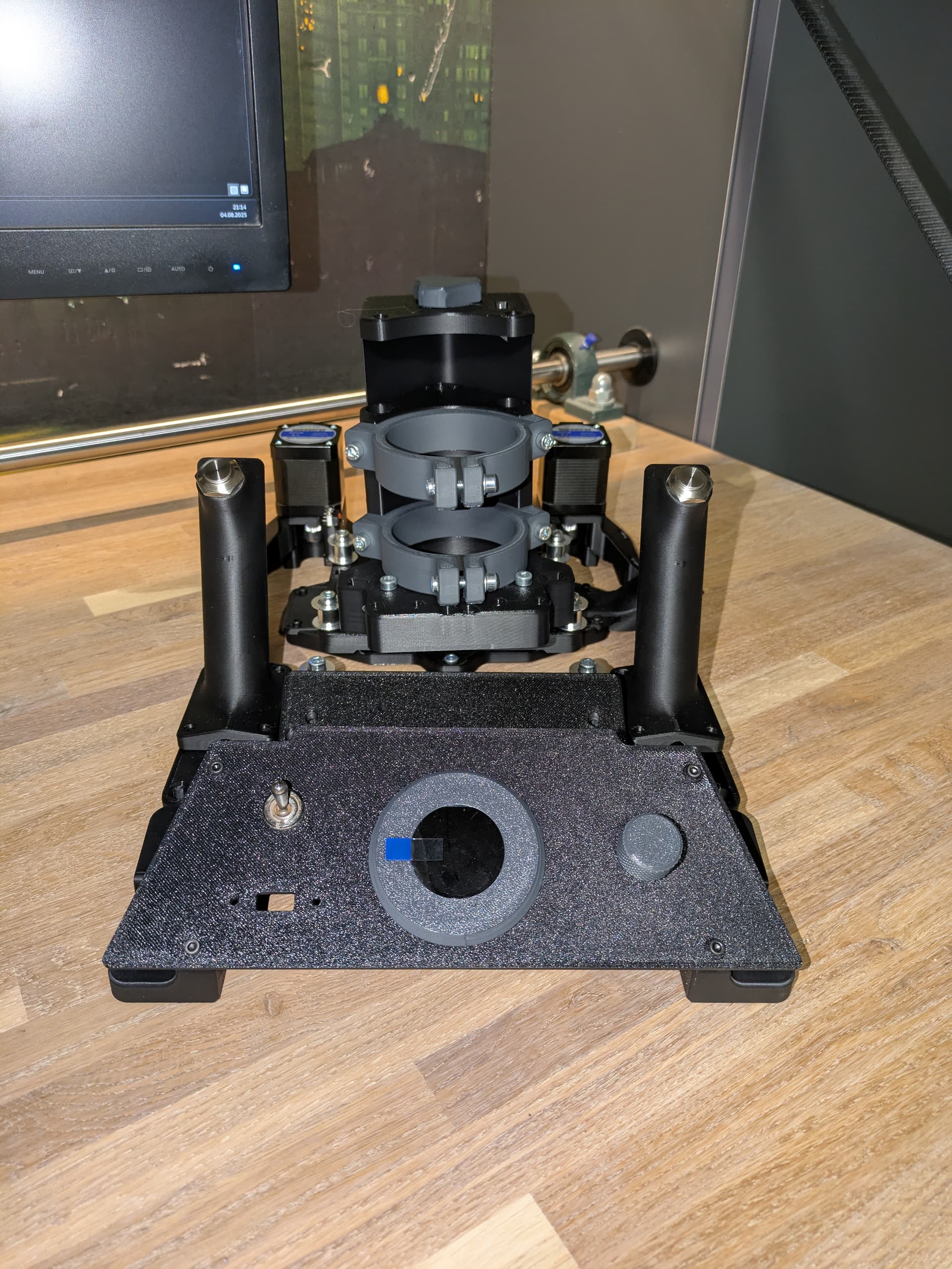
First parts printed and partial assembled. Waiting for my alu base plate.
Cant wait to draw the first sine wave ![]()
7 Likes
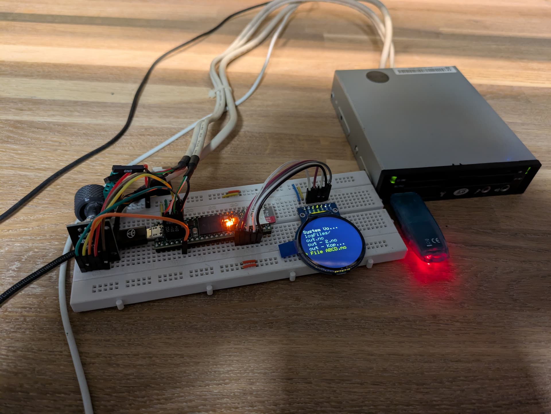
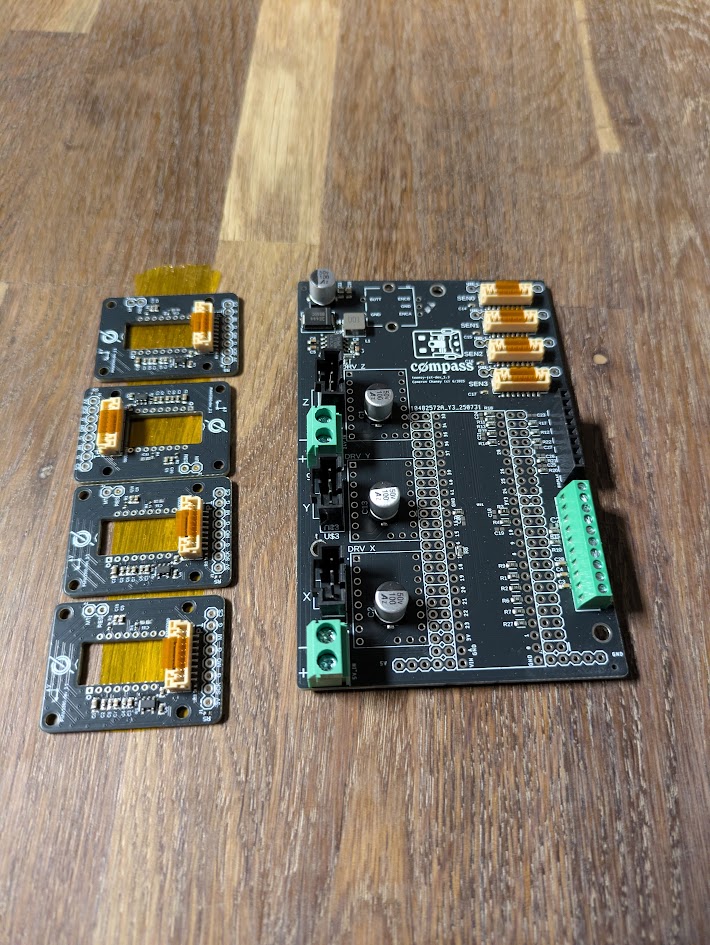
Say hello to my development board ![]()
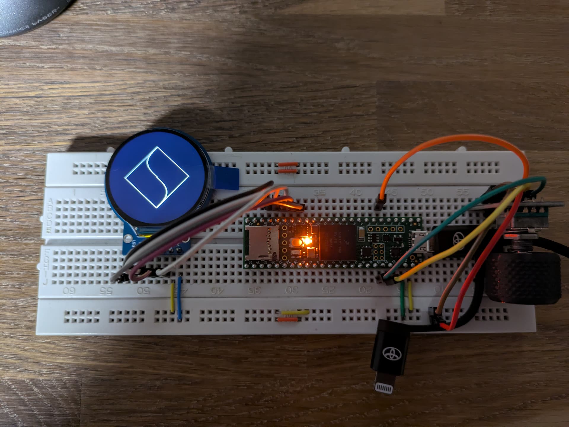
Monday should arrive my usb host cable. Now i have something to do, before the next parts will arrive.
2 Likes
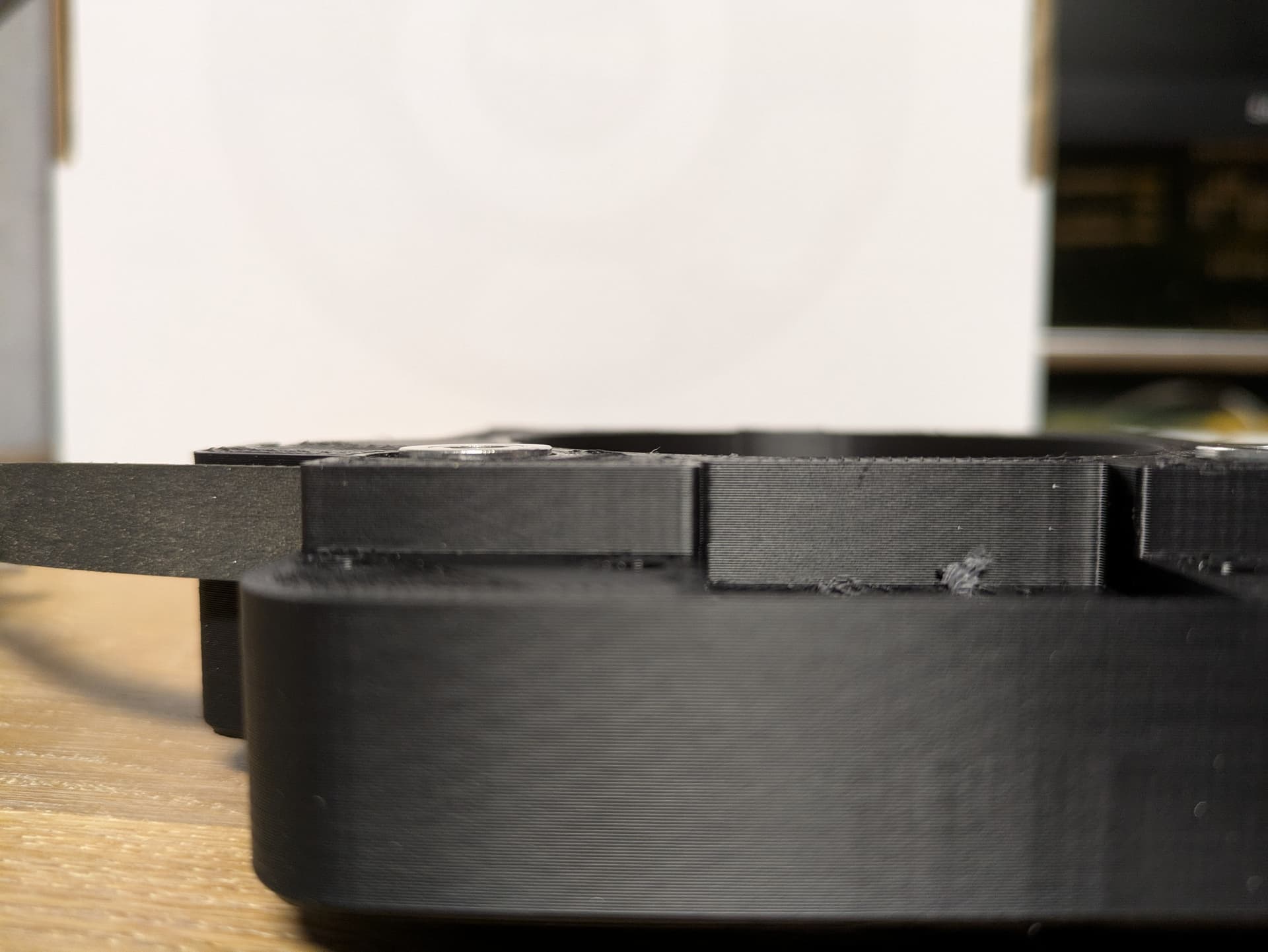
Next part printed and partial assembled. The X Stage Plate.
The Tensionsystem is gorgeous! I need to build new brackets for my Low Rider 2 with this system.
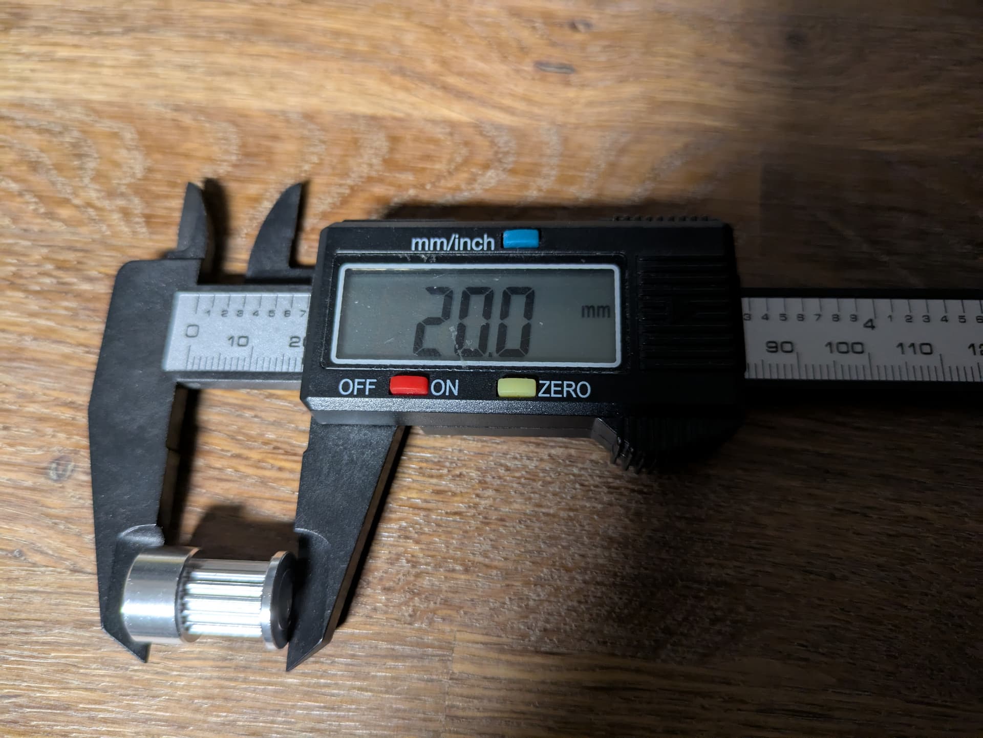
To all builders who put their components together themselves, my GT2 drive pulleys were too long. I had to file them down a bit.
I Hope it ist enough and i have enough clearance.
Before filling:
After filling:
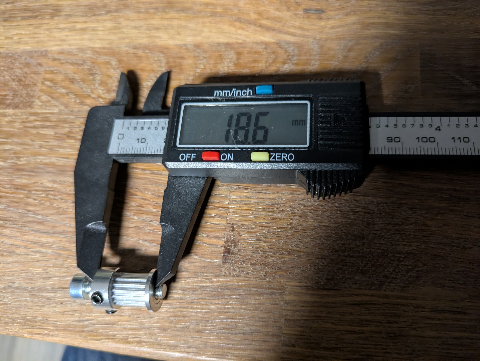
The Result:
3 Likes
Big parts printed and partial assembled.
Front plate is waiting for the usb connector.
I found in my spare parts box an old usb card reader.
I was able to implement the usb stick support ![]()
7 Likes
Looking great! Glad you appreciate the tensioning system — I am proud of that one
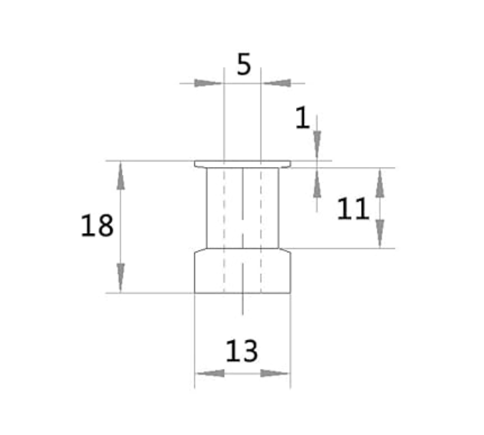
I just had the same realization with the drive pulley height. I ordered from a different Amazon supplier for my instructional build and got 20mm instead of 18mm (this one should be good: Amazon.com). Note for filing: you might want to file 0.5mm off of the bottom side if you can as well to try to match the desired dimensions better:
Are you planning on mounting everything to a PCB, or sticking with breadboard?
My PCBs are on the way. The breadboard was only for testing and deveopment (I used also a different screen).
Coolio!
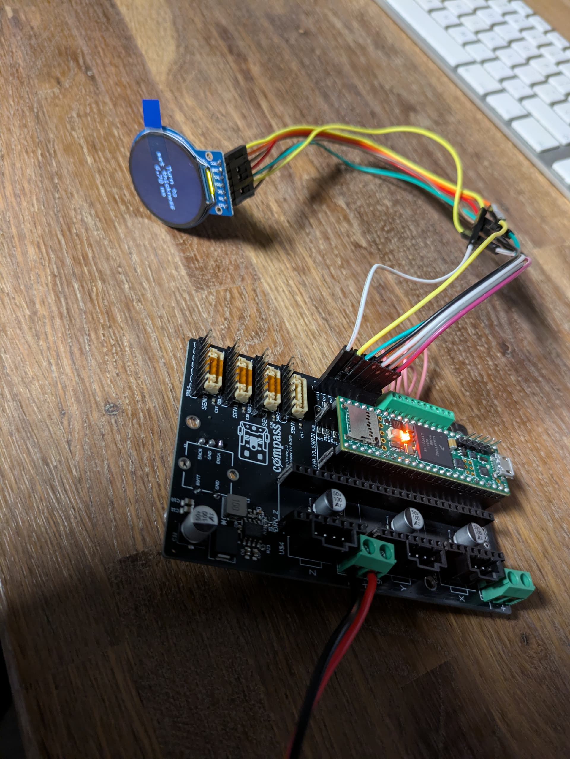
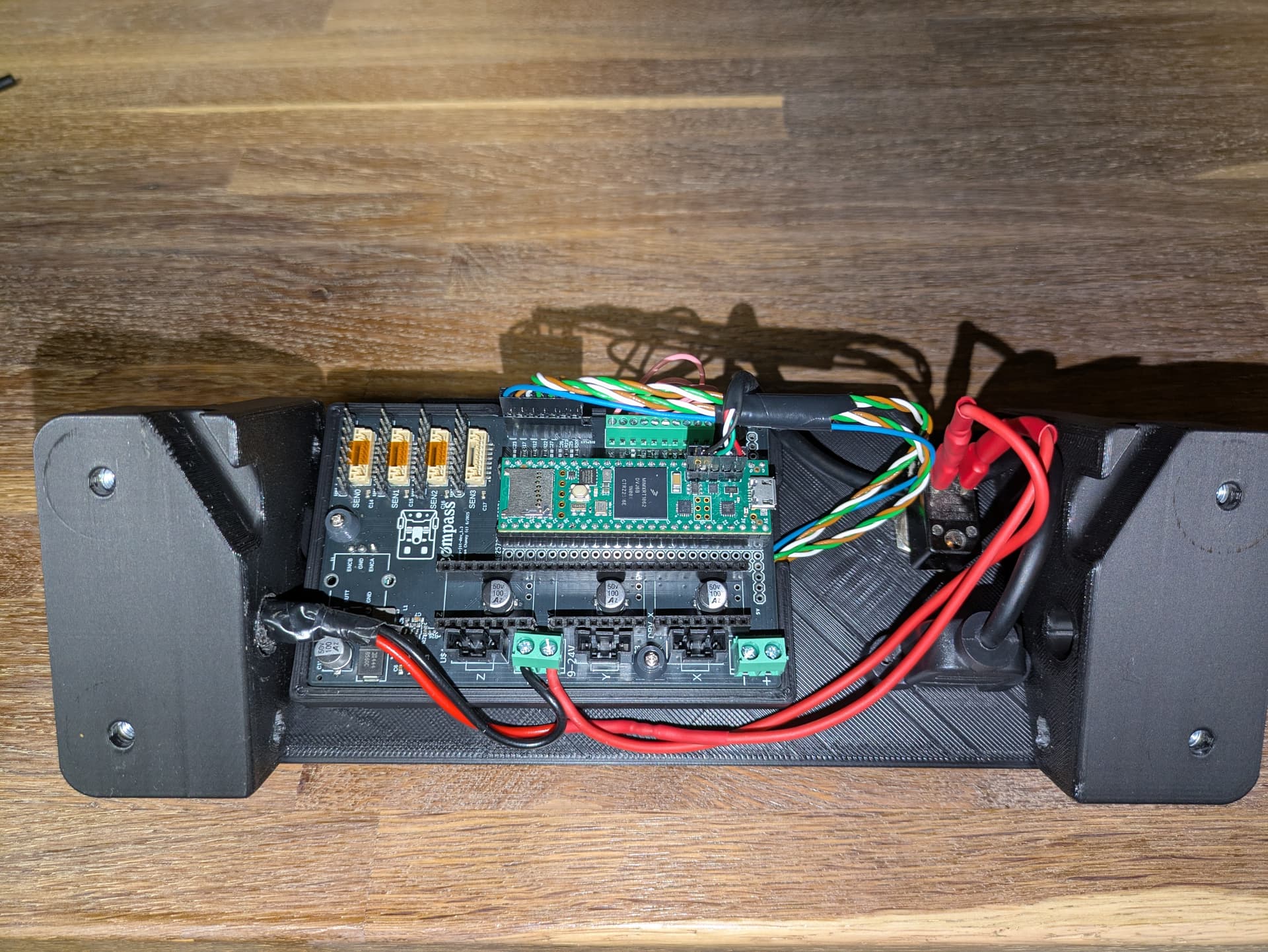
Mainboard ist soldered completly.
Screen, encoder and Endstop contas works fine.
I hope my stepper driver arrived the next days.
Tomorrow is crimping time!
1xScreencable and 4xSensor cables.
JST GH is to small for me ![]()
So I will solder my CAT5 cable directly to the sensor boards and on the main board side I will use dupont connectors with hot glue or a 3d print holding braket.
The contacts on the mainboard are to small for JST XR conenctors ![]()
1 Like
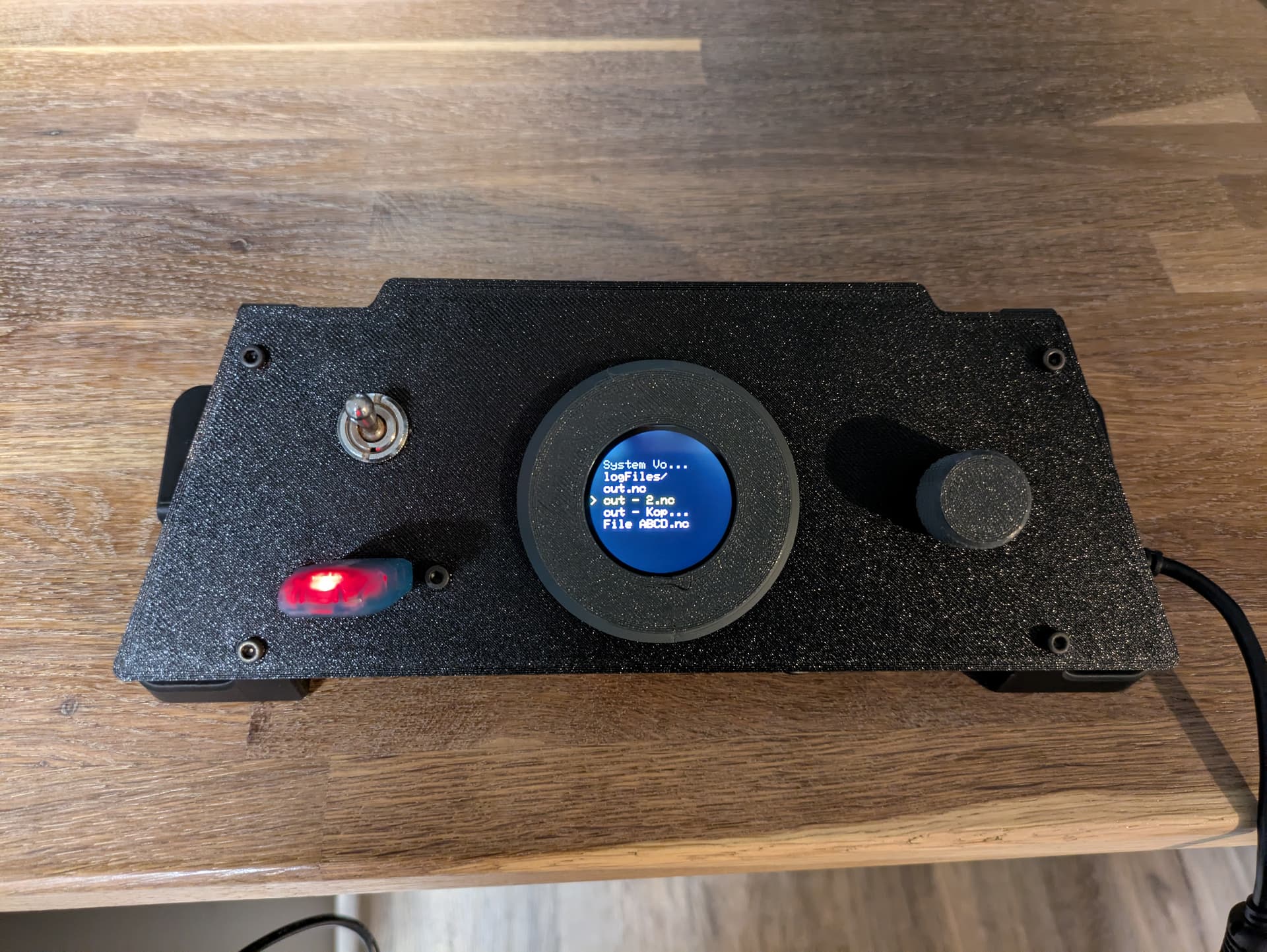
Today all my remainig parts arrived ![]()
I assambled the everything for a test fit (need to take it apart again to install the sensor boards).
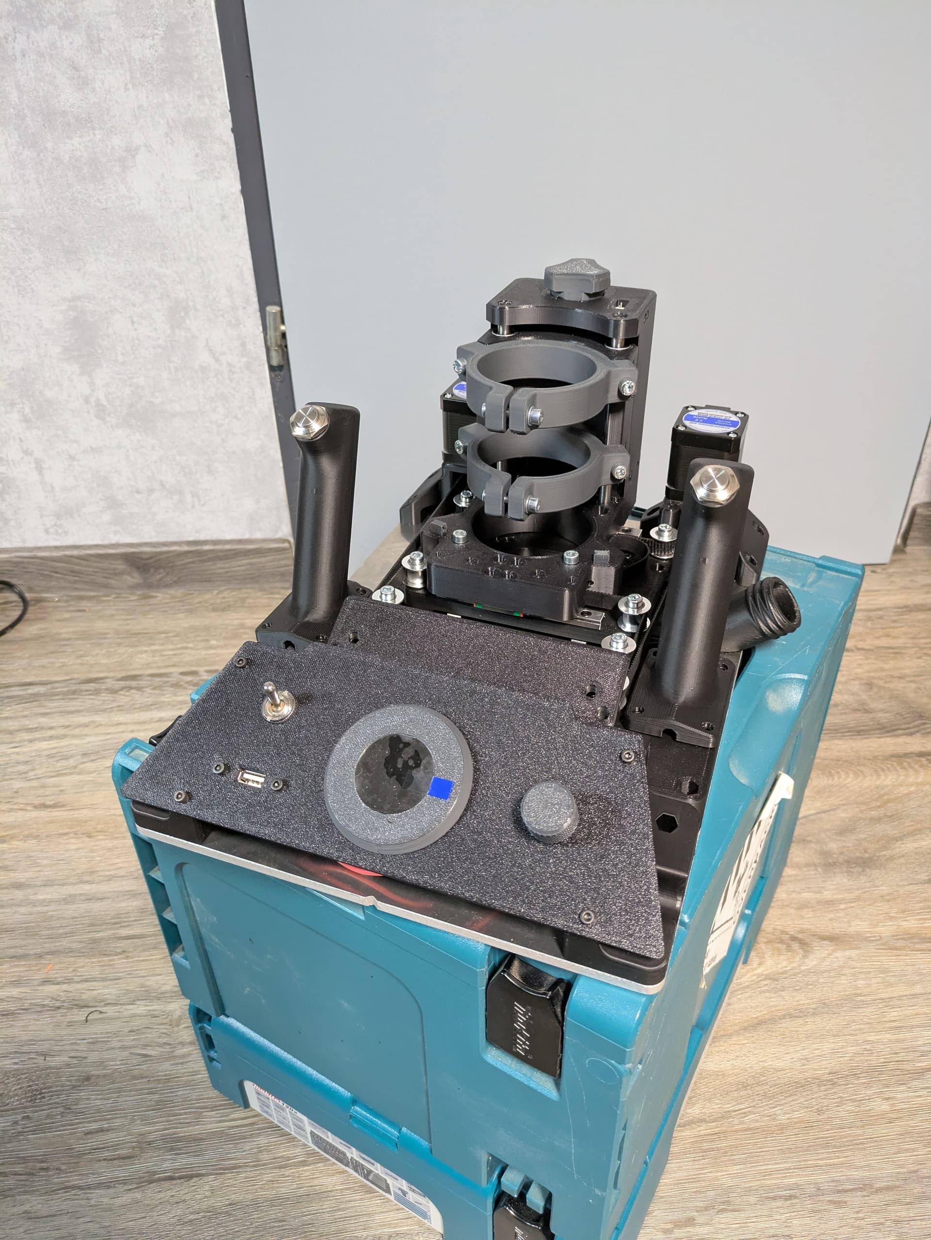
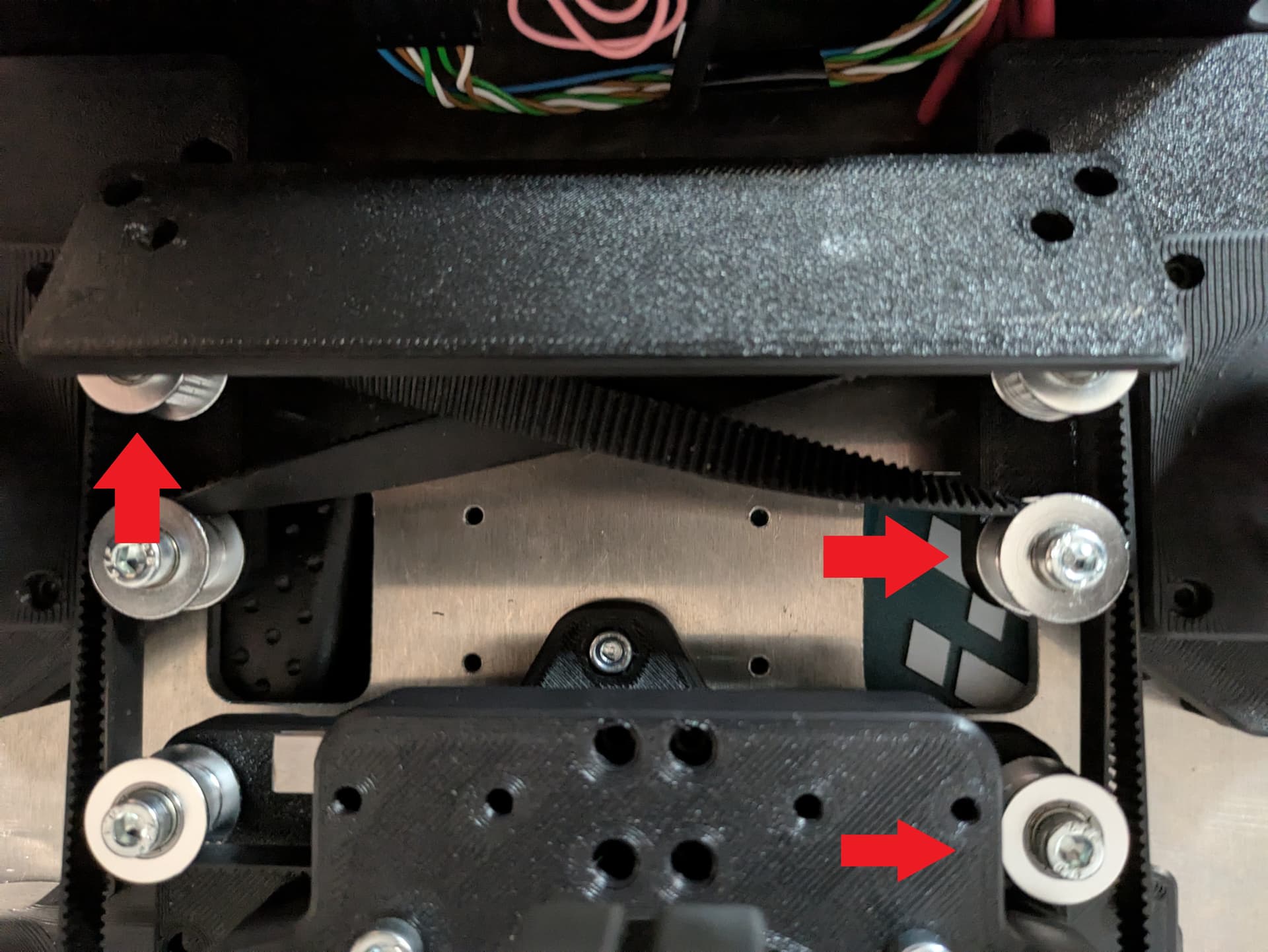
I am not very happy with the belt crossing. I think we could raise this 3 pulleys with 2 or 3 washers.
1 Like
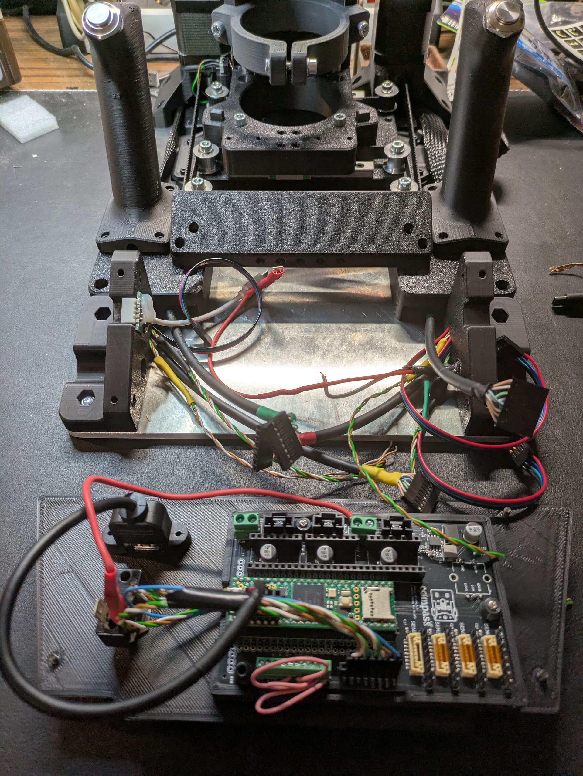
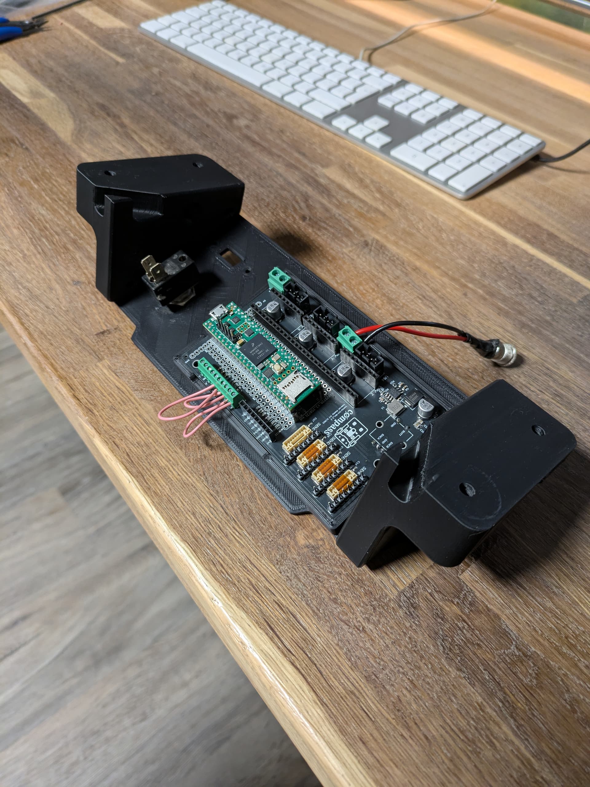
Sensors are assembled, all switched wird.
No i need only to plug everthing in and Install the Stepper drivers ![]()
5 Likes
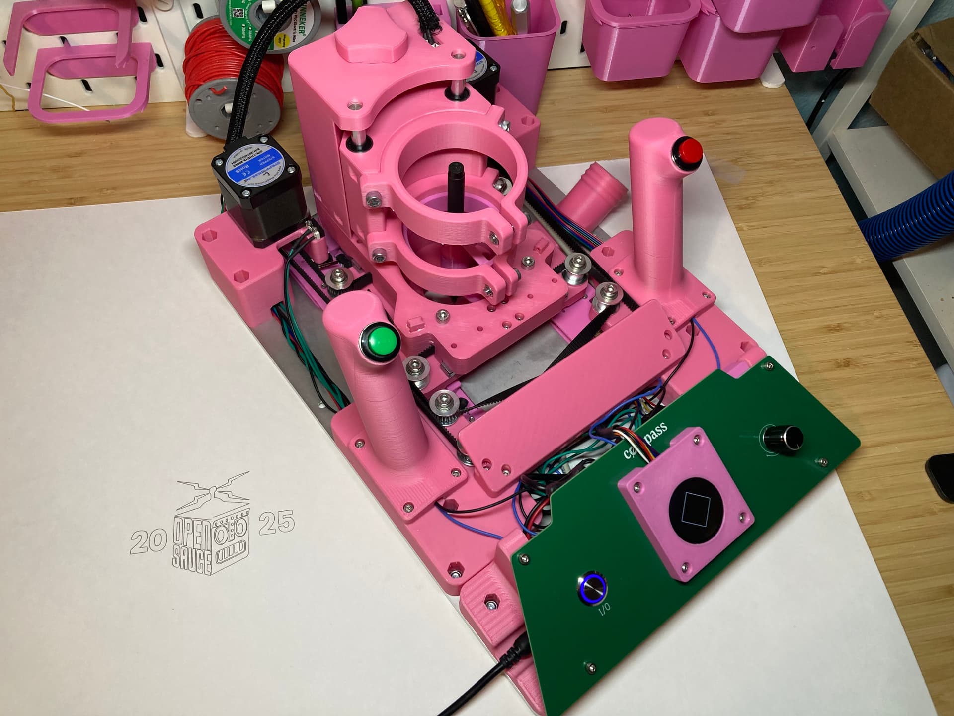
My First results ![]()
After First calibration. I must have done something wrong.
After second calibration:
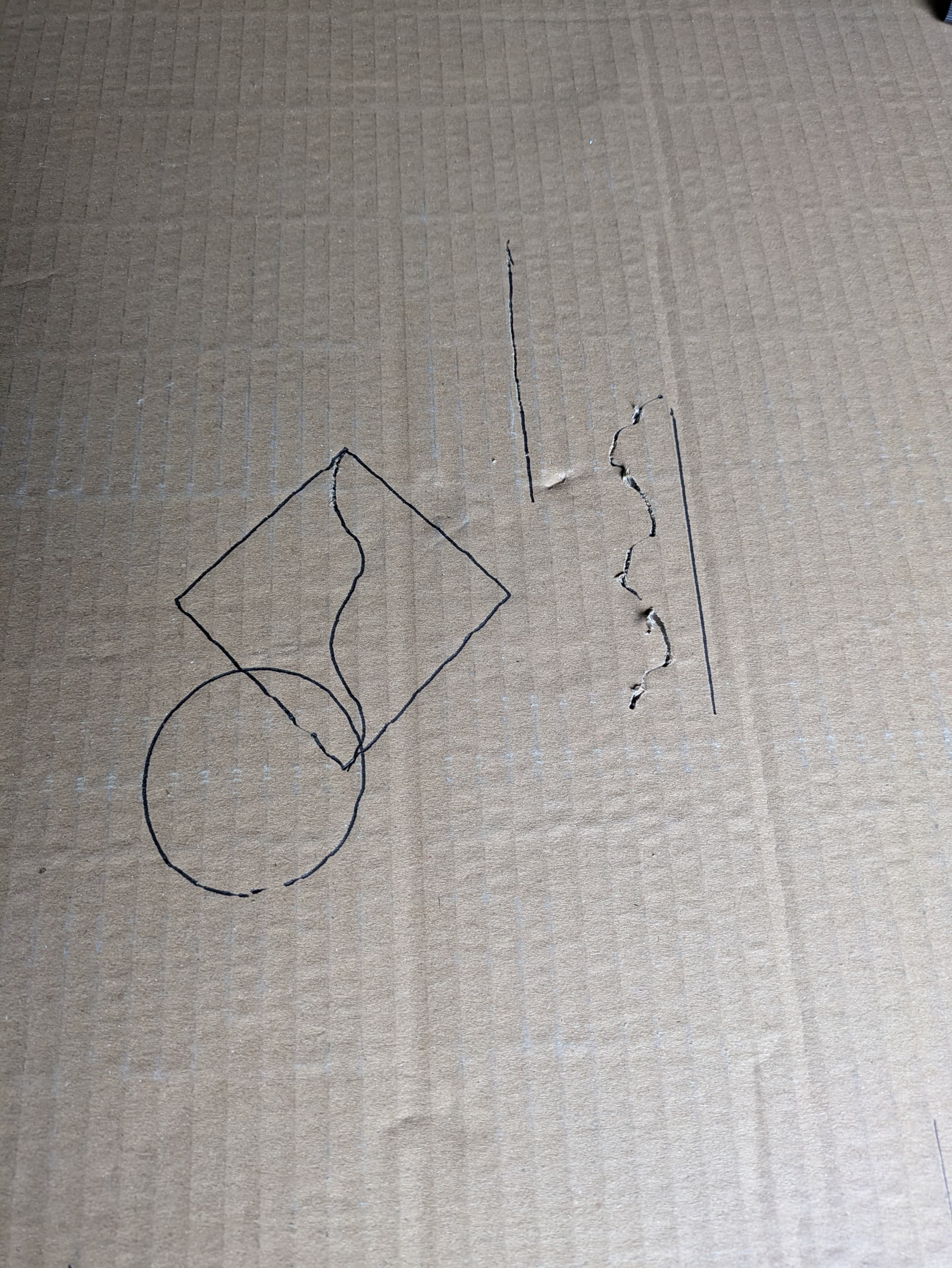
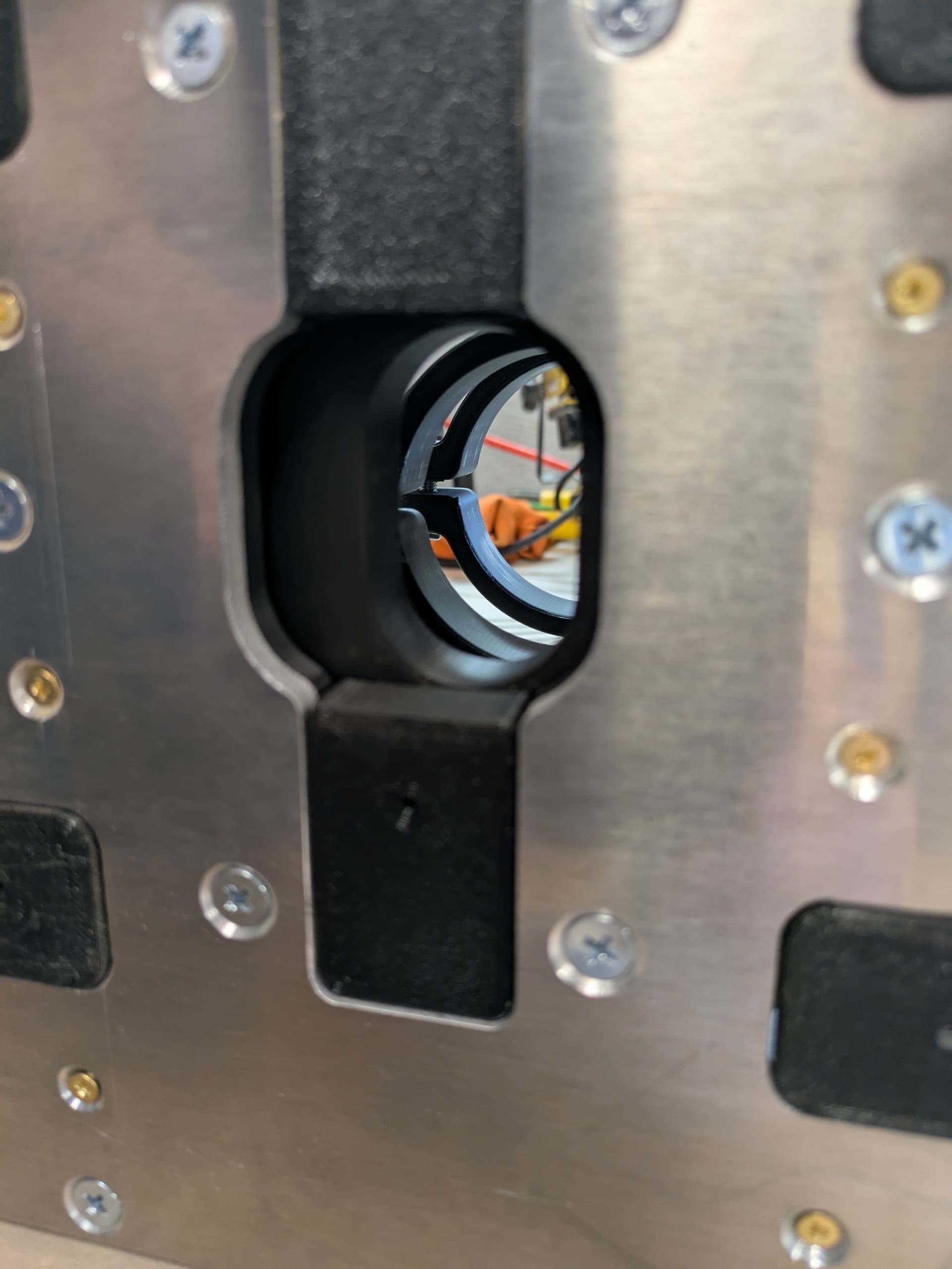
I printed the pen holder with the flange. And mounted it backwards. So there was a lot of play in the pen. I’ll try again tomorrow with better material. And correct installed pen holder. Or direct the Router ![]()
1 Like
I haven’t tried the Compass but I noticed while drawing the crown on the Lowrider 3 that not only does the pen move but also the paper. So after “taping” the paper/cardboard/whatever down I got a better result.
1 Like
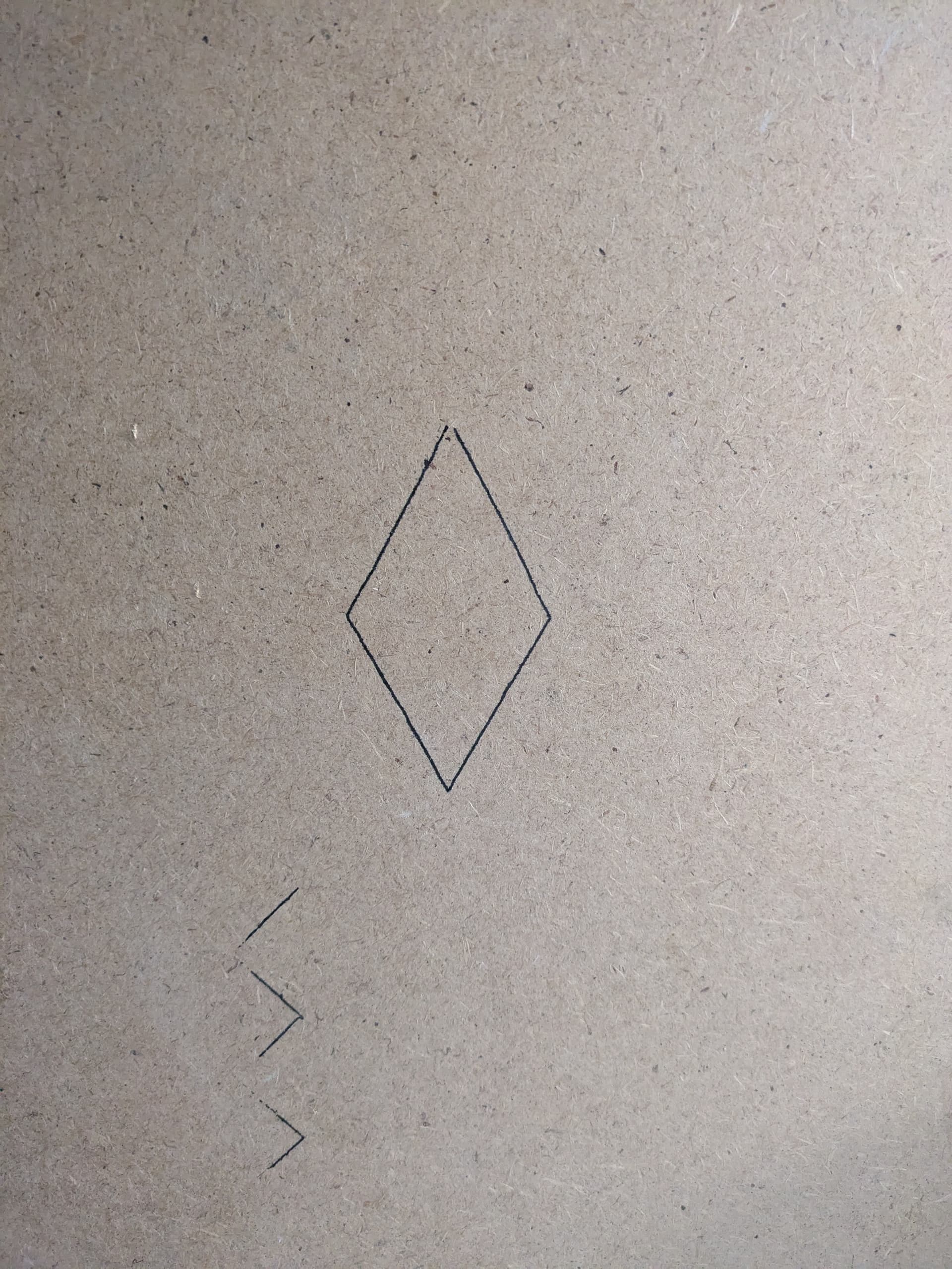
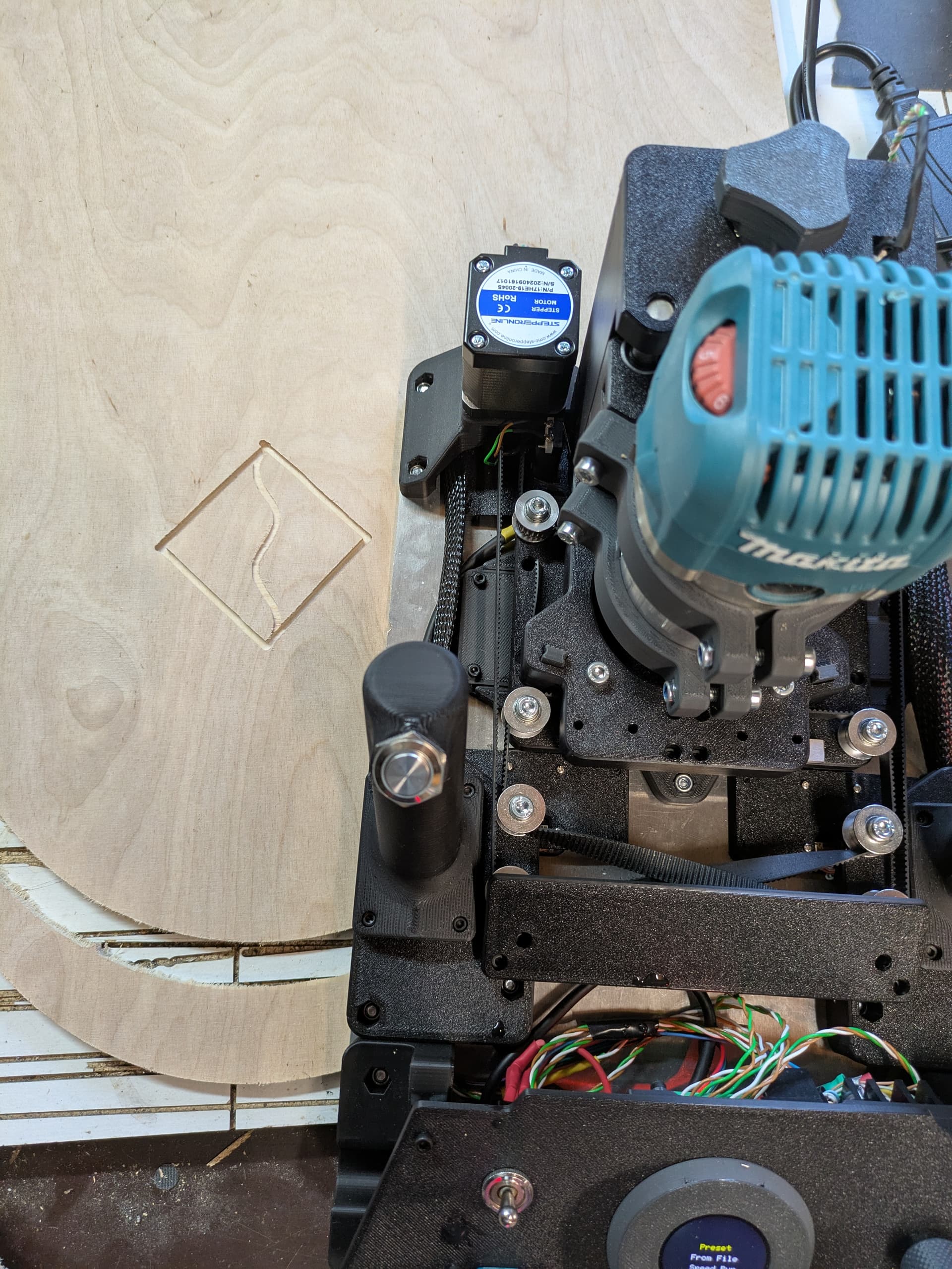
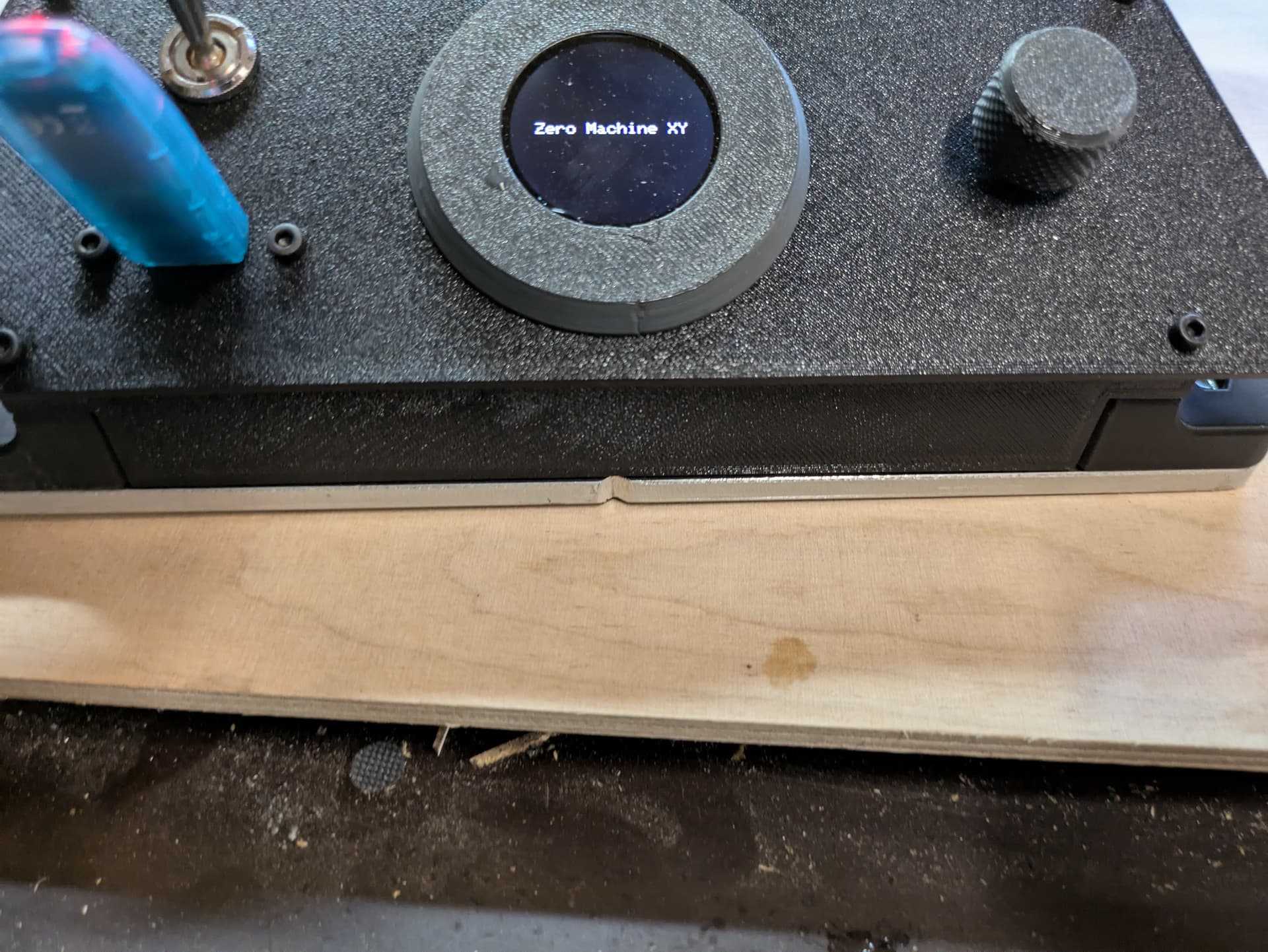
First test milling today. Works Smootly.
Unfortunately I still have a calibration problem. The rectangle is more of a diamond. The dust suction is really very good, look at the photo, no dust to see.
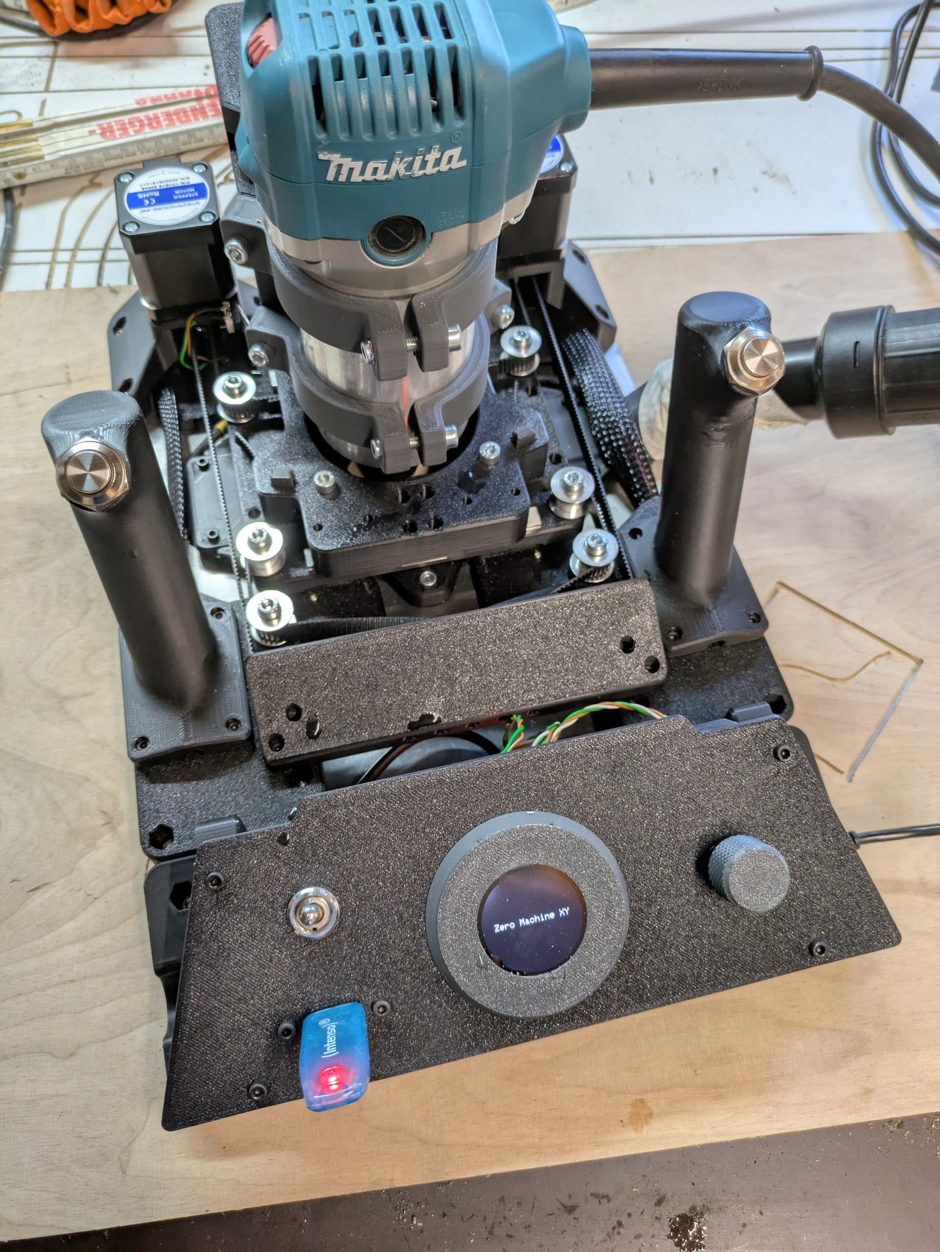
I have already closed the machine at the front. The back is a little harder to design, but that will be fine.
I tried to implement Z Touch today, it’s way too slow about UART alone. I have to connect the driver’s Diag pin to an Interrupt pin of the teensy.
Just have to find a free one.
4 Likes
Perhaps you could show a video?
Wowwww so impressed you got everything up and running without any instructions!! Good stuff. Finished them just in time for you to be done lol:
Put PFTE tubing in the shieldSeperator to keep the belts separated (look at instructions for more info). We want to keep the belts on the same plane, so we don’t want to raise any of the pulleys.
Yeah I could definitely see there being an issue in the pen mounting. It should look like this, with the flange lined up with the bottom router mount:
Also nice job on the wiring, that looks cleaner than anything I’ve done!
Is the Z stop not already on an interrupt pin? Can’t it just be shorted to Z stop connector so they are in parallel?
Yes, but I want to keep the physical limit switch.
Without instructions, it’s not quite right. Version 0 helped in many places, as did the step file for the entire machine ![]()
Regarding the V1 instructions, I would recommend installing the sensors before the L R motor mount and the pulley idlers.
I had the most problems connecting the motors. It was my first experience with a Core XY, and it moved in all directions except the right ones ![]()