Would be great to see a video or power point presentation showing every step involved with creating a carving or sign. From getting a picture to getting it into the proper format to bringing it into EstlCam to creating toolpaths and controlling the MPCNC.
I am using EstlCam to create the g-code, place the file onto a SD card, place it into the MPCNC controller box, set the axis’s to zero and proceed to print(carve). Invariably, the z axis doesn’t go down deep enough to do the carving. I’ve also tried connecting laptop directly to MPCNC controller and using repetier host with mixed results. Setting the z axis seems to be an issue. I am quite computer literate but something is eluding me in working with the MPCNC. Thanks
Will not allow me to post the Estlcam file or g-code file
I’m surprised the forum did not allow you to upload a g-code file. As long as the file is not too big, the forum software allows g-code files to be uploaded. As an alternate, we can usually tell what is going on if you paste the first 25 lines of the g-code file into your forum post. Estlcam files can be uploaded if they are placed inside a ZIP file first.
The issue you are facing is most likely due to you not resetting the Z position to 0 before cutting. Using any text editor (like notepad), open your g-code file and insert the following as the first line in the file:
G92 X0 Y0 Z0
This command sets the current position of your router bit as the origin for your job. You need to have the tip of the v-bit touching the top of your stock and at the origin point as you have it set at the origin point you defined in Estlcam before running your file.
If this solved your problem, post back and we can provide you information about how this command may be automatically inserted g-code file, or how it can be executed from a menu item.
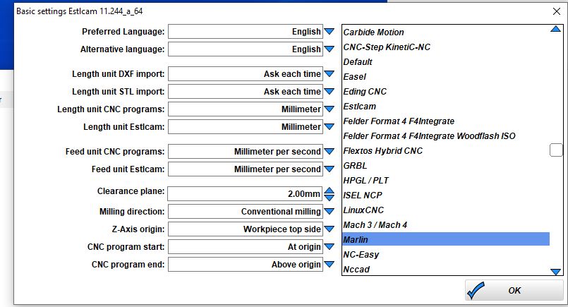
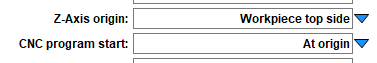
You may also want to check in Estlcam/Setup/Basic settings that you have the following:
If this did not solve your problem, provide us a more detailed explanation of exactly what you are doing along with the first lines from the g-code file.
Looking at the g-code file, it is v-carving something that is approximately 50mm (2") wide and 6mm (1/4") tall, and the maximum depth of cut is about 1.5mm. Does that make sense with respect to what you are attempting to carve? There is no G92 in the file, so what exactly are you doing to “set the axis’s to zero?” The job is expecting the tip of your bit to just be touching the top of your stock and be at (0,0,0) relative to the stock.
The most likely source of your problem is the resetting of the origin point at the beginning of your job. Also, v-carving is extremely sensitive to irregularities in the top of the stock and having the plane of the router parallel to the top of the stock. If you think either of these could be the cause of your problem, you can surface the top of your stock with a flat endmill before you do your v-carve.
Thanks Robert. I am using EstlCam to create the g-code, placing the file onto a SD card, placing it into the MPCNC controller box, setting the axis’s to zero using terminal and proceeding to carve to print(carve). The size is irrelevant at this point as I am just trying to get a successful carve. My ideal size would be approximately 5.5" high, 14" wide, 3/4 thick material
I have straight cutting bits but guess I need to change the tool list to reflect it though it looks like I have 1/4 bit selected.
The ZIP contains the g-code file, not an Estlcam file, so it doesn’t provide any more information than the g-code file you’ve already posted. Posting a saved Estlcam file (inside a ZIP) would be helpful. Note I personally am not an Estlcam user, but there are a lot of them on the forum, so, when you post the file, someone will take a look and give you feedback.
setting the axis’s to zero using terminal
What terminal? On the screen on an SKR Pro board? In Repetier-Host? What is the exact command you are sending? I just want to be absolutely sure the origin is getting set correctly.
I have straight cutting bits but guess I need to change the tool list to reflect it though it looks like I have 1/4 bit selected.
If this is v-carving like I suspect, then you need to define a v-bit.
I can only compress the Estlcam file 2% which is still larger than the forum will allow to upload.
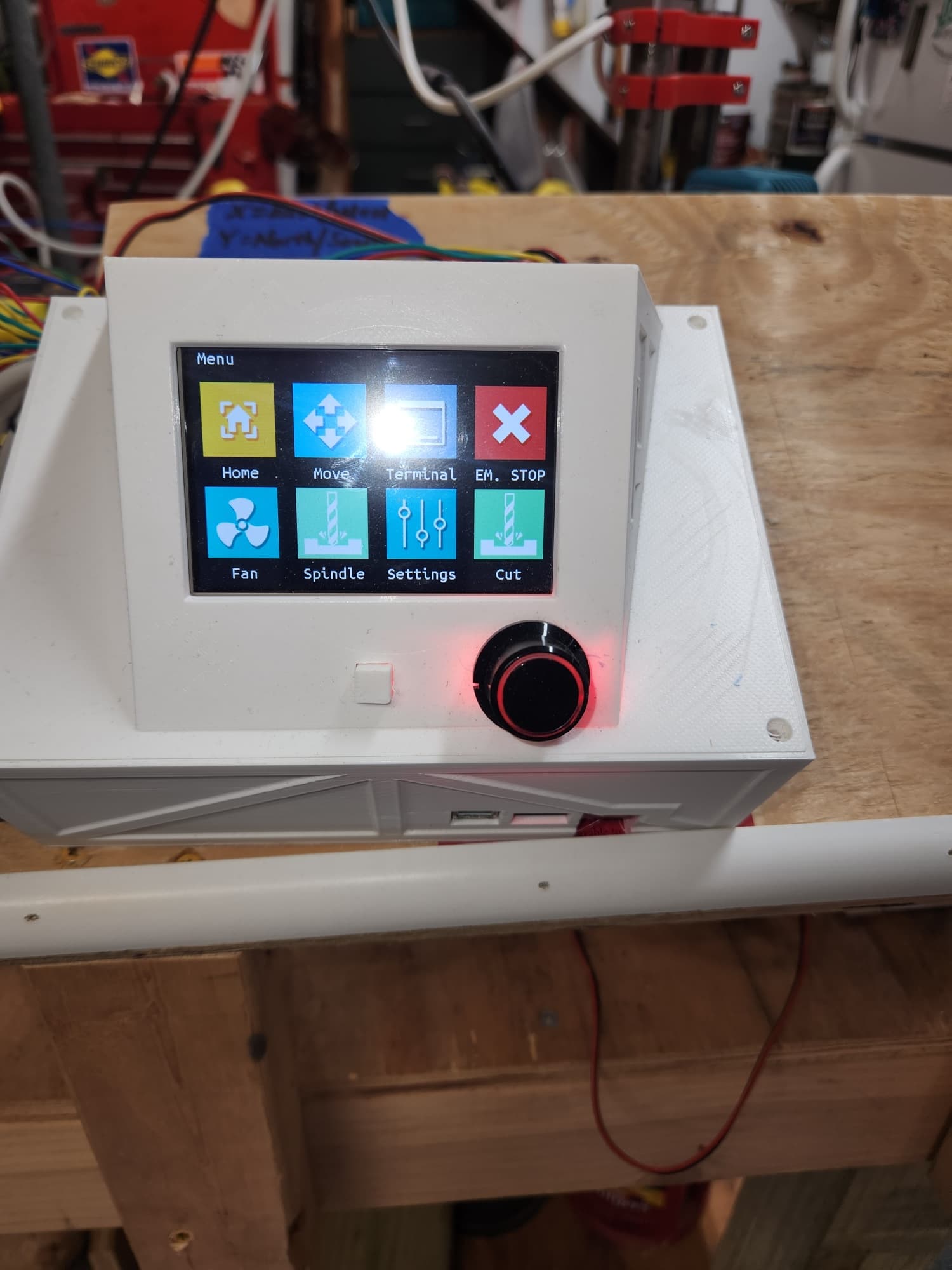
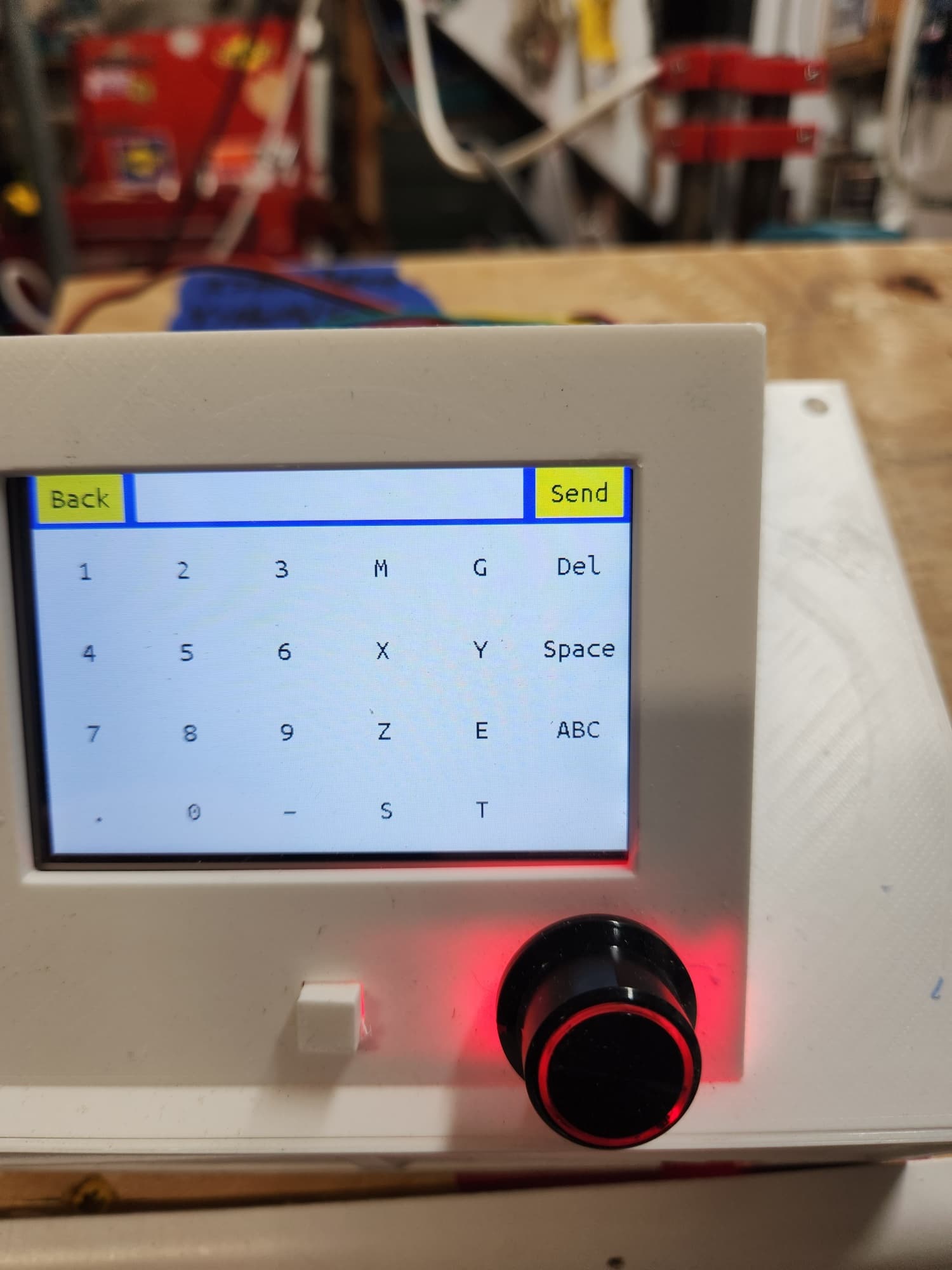
I’m using the terminal on the control panel, 3 separate commands G92 X0; G92 Y0; G92 Z0.
Try this I added one line of code from the milling basics page. It should work, if it does simply add
G92 X0 Y0 Z0 to the starting gcode section of estlcam.
To use this, power the machine, use the control panel to drive it to your starting Zero position. Just touching your material. Then hit go.
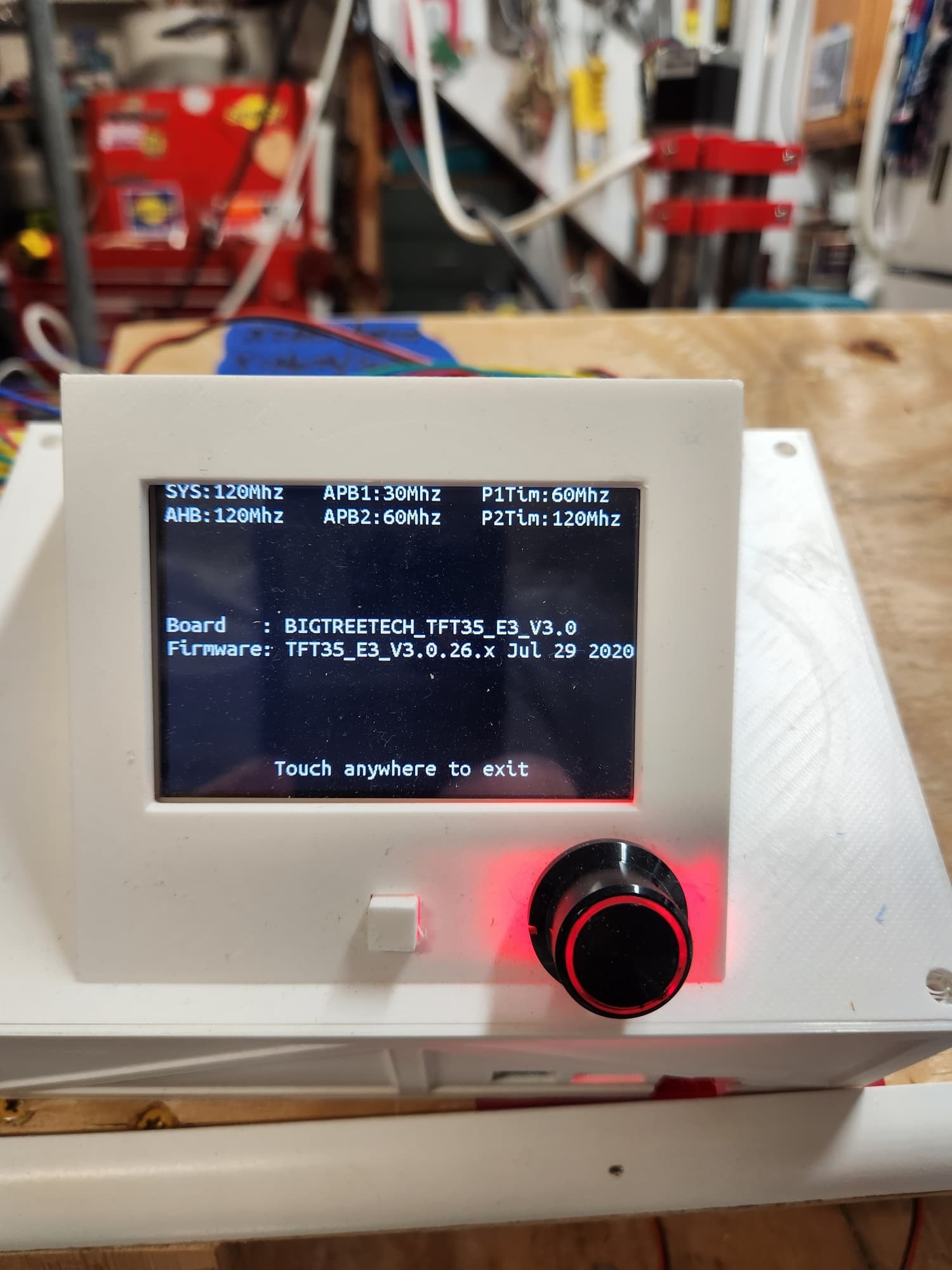
Another note I need to give you is run it from the Marlin side of your LCD screen. Hold the selector knob in for 5 seconds to select the other side. That firmware on your screen is more than 2 years old and was heavily modified. And at that point Marlin mode was the only one we really trusted. The current firmware is much better but the fancy custom buttons are gone.
If it works you can then try the touch enabled side of the LCD screen, to see if you have issues on that side or not.
I have placed the zero commands to the gcode file…the router moves from the zero position out to the field as if to start carving, but then just stays there in one spot. Does the G92 command need to be down under the :No.1: Carve 2 line?
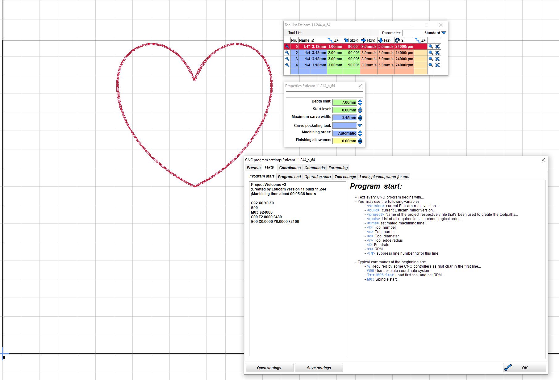
Sorry, losing track of who/what I’ve responded to and I guess responding to email responses doesn’t go through. Attached is the settings from my Estlcam setup. If I can get a successful Estlcam gcode file I can try it on mine to see how it does. If successful I can copy the settings. estlcam setting welcome sign.zip (592.3 KB)
That file in english for any line that start with G.
All axes set to 0
Use relative motion
Move to zero - nothing should happen as it is already there.
Move Z up 2mm
Move over to x15 y136.
Move Z down to -0.7mm - tiny cut under the surface
So use that to tell me what exactly happens. The first move you see what is it? Z up 2mm?
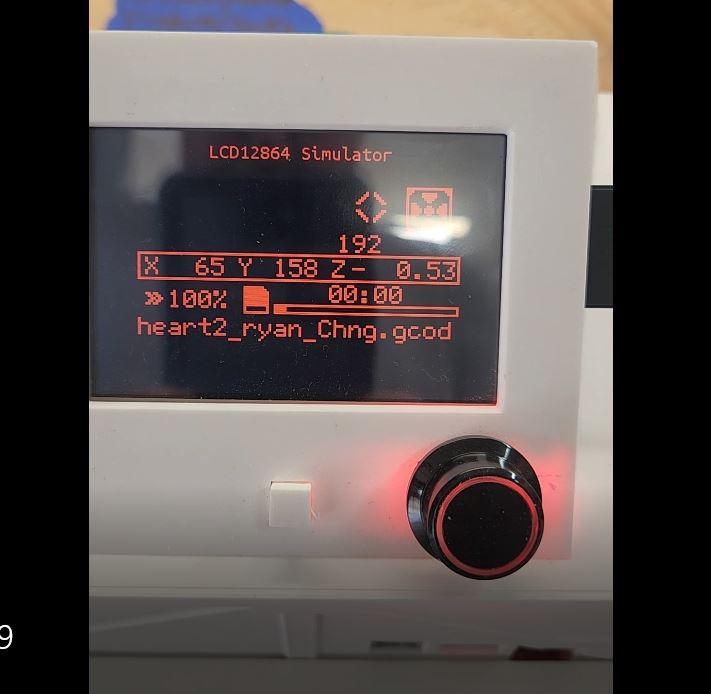
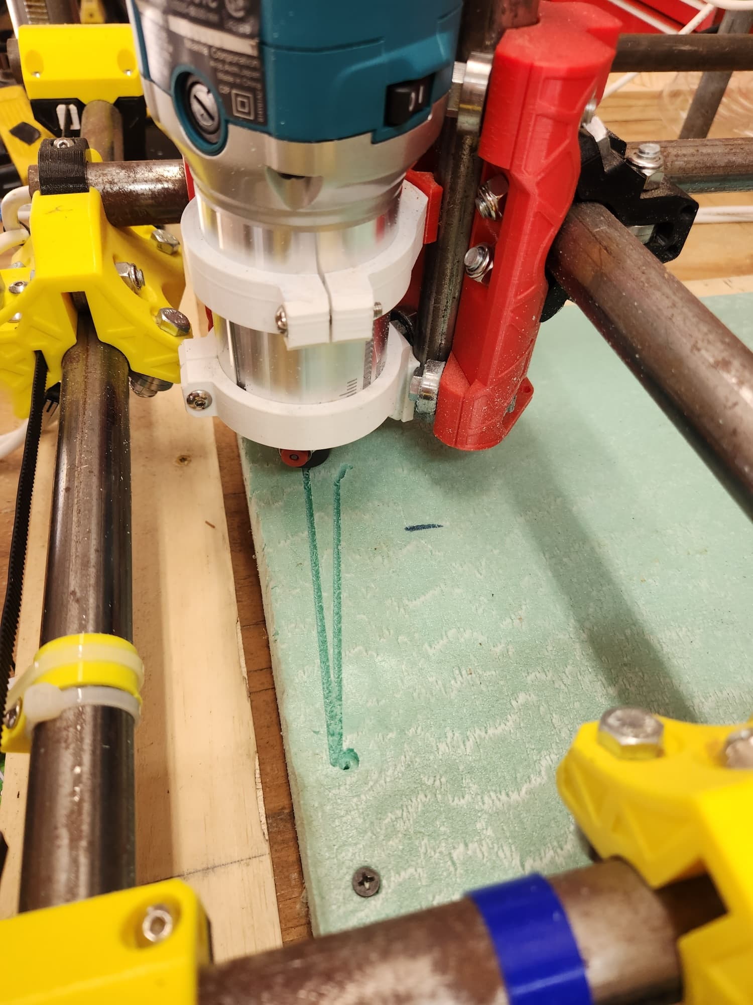
Will call it a success…I abandoned the GUI interface altogether and used the Marlin side of the screen. Did not turn the router on until I could see what was going to happen. Have to work on sizing and depth of cut/s. Hopefully the video comes through. The 2 vertical lines were from yesterdays efforts.
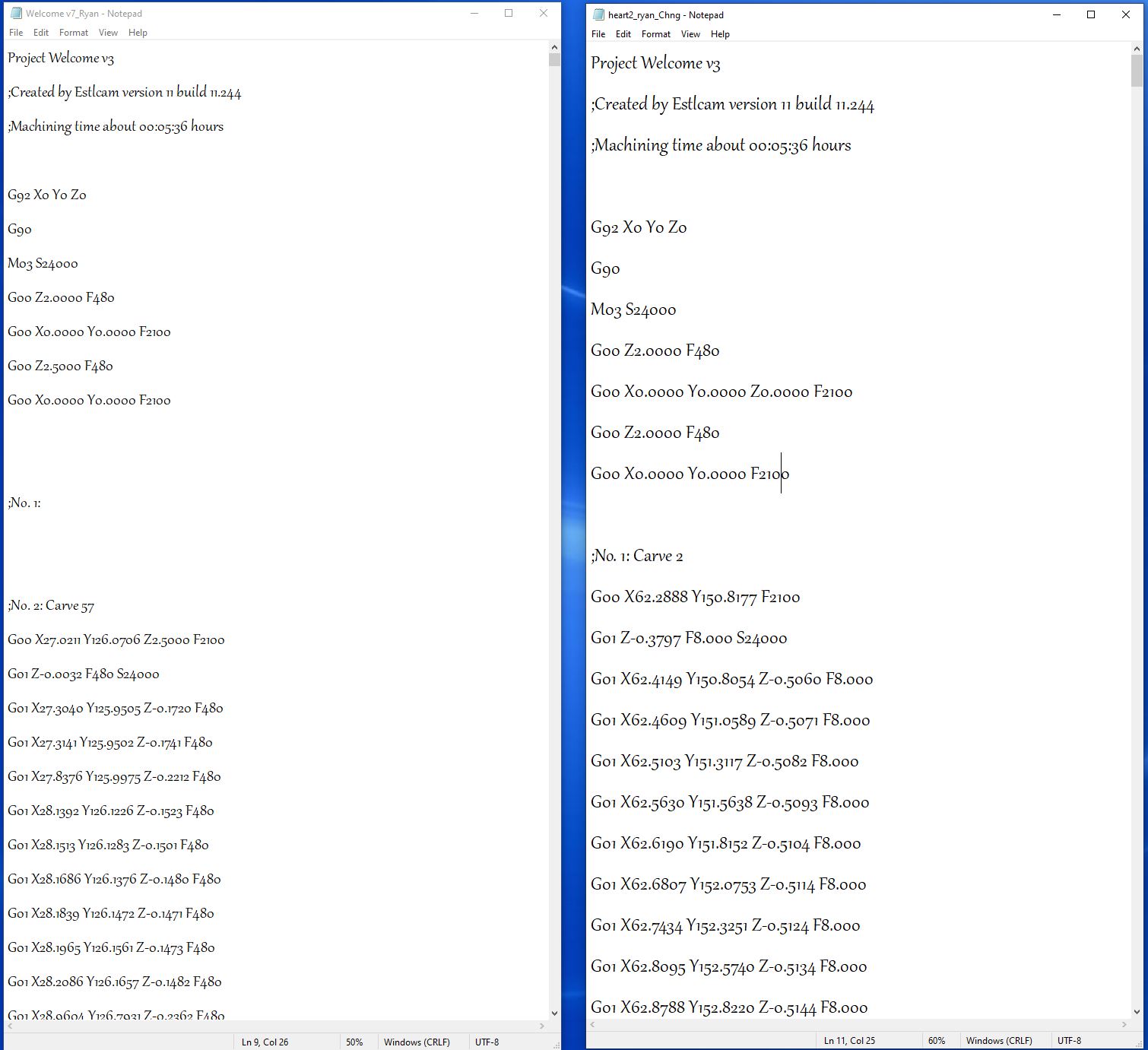
Ok, loaded a simple heart picture this morning into Estlcam. Added Ryans gcode amendments to it. Loaded the gcode through the Marlin interface. The router moved to the designated starting position…YIPPEE!!!..and then just stayed there . Thought I had finally conquered this. :unamused. Added the start of the Gcode files, left was a success yesterday. Right one from this morning, no success other than the router moving.
The issue with your file is the feedrate. Take a look at the first G1 line:
G01 X62.4149 Y150.8054 Z-0.5060 F8.000
Your feedrate is 8mm per minute, so it is carving your heart, but very slowly.
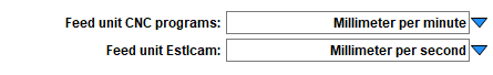
Usually when we see this problem, Estlcam has this setting in Setup/Basic Settings set wrong. It should be set like this:
Edit: I took a look at your good and bad g-code files. Take a look at the F parameter of each G01 line. One file is F480 and the other is F8 , so one is moving at 480mm per minute and the other 8mm per minute. I’m not sure what you did that one file is okay and the other is so slow. Usually, the issue is with the setting I outline, but it would be wrong for all files, not intermittently wrong. Did you reinstall Estlcam?
Thanks! I changed the gcode file to replace all the F8’s with F480. Saved it as a new gcode file and loaded it. The gcode file ran, but the bit never engaged the insulation board so I need to look at the carving path configurations I’m guessing.
I did not re-install Etslcam, attached is the setup screen you referenced…
Ok, seems as if the speed in the tool list was incorrect…was 8 vs 480. Changed that and saved a new gcode file. Ran it and the router moved as if it was cutting the heart. However, the bit still stayed above the insulation board. The router raises as to clear the material, but don’t think it ever goes back to the original z position to lower it and start carving.
Looking into other parameters that may affect the depth…am on the cusp, can just feel it…when successful will have a double shot of tequila!! LOL
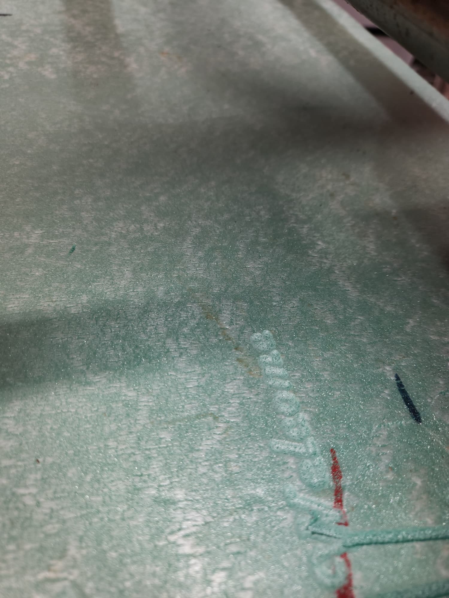
Taking another look at it, I am not sure what is wrong with your path. Why are there a bunch of circles? I think you were trying to get Engrave, not carve.
I don’t use Estlcam, so I cannot give you a precise answer, but you are attempting a v-carve. V-carving uses a chamfer (angled) bit and moves the bit up and down to maintain the width of the bit on the edge of two lines. You define the maximum carving width as 3.18mm, so how deep it will cut will depend on how you defined the angle of the tip of the bit. In addition, you limit the width of the cut to 3.18mm. If you had defined a chamfer bit like this one, given your limits, the deepest the bit would cut is 1.6mm.
When I look at the g-code file, I do see Z movement, but the maximum depth I see is only 0.7mm.
I you are just trying to get things up and running (i.e. you are not attempting a specific project), I suggest you try an engrave toolpath and the other toolpaths and come back to v-carving after some successes.
 . Thought I had finally conquered this. :unamused. Added the start of the Gcode files, left was a success yesterday. Right one from this morning, no success other than the router moving.