How I set up and use klipper to control the LR4 cnc

Background: in the interest of reusing electronics that are now in abundance, this thread may be of interest. The goal is to show how to set up klipper for the mpcnc or the lowrider using some of the legacy hardware that may be obtained from older 3d printers or more recently upgraded cncs. For example, i recently acquired a teva terantula that had an upgraded skr1.4 board on it with 2208 drivers. The trolley and supporting pla was melted and the frame loose and rickety. I got 4 good motors, some extrusion and a good controller for not much cash. I also picked up a rpi 3 used as well. All i need is another driver and a motor off something else and i can build another lowrider for a friend, which is likely.

I’ve been hesitant to publish this about klipper in part because it isn’t always the easiest thing to set up and it does not work with the jackpot board since esp32 is not a supported board by the klipper software. As far as cnc control goes though. it is a workable option and useful. I’ve used it for the past 2 years now for cnc and it works great.

The only difference real between printing and cnc is you remove the extruder setup and put in zeroing and probing macros.

If you know how to set up and use klipper for a printer it is arguably easier on the cnc.

Required parts:

  • control pc: this could be a linux box. A raspberry pi or other branded single board computer. A pi3 is more than sufficient for this. A zero2 will work as well, but youll need some usb adapters. I’ll refer to this device as the raspberry pi or rpi from here on.
  • Cnc Control board: 5 channels of motor control. This can be 2208, 2209 or perhaps other motor driver chips. My experience is limited to 2209’s. I’ve used skr pro, Skr turbo, Mini e3v3, trigorilla (customized arduino mega), and Mks boards off of upgraded ender printers. Any printer board will work and if it doesnt have enough channels, you can use 2 different ones together to get your 5 channels. The only suggestion is to have both channels on the same axis on the same board: z together and y together. This device is typically hard mounted to the gantry. I’ll refer to this device as the skr from here on.
  • Control device such as laptop or phone to upload job and start and stop or pause. I have an all in one pc in my shop and i use s phone or my design laptop that generated the gcode.
  • Pinout diagram(s) for your board(s) with the pin labels for configuring your printer.cfg file. This is the tedious part requiring patience and some time, but it isn’t terribly difficult.

Optional components
*A dedicated klipper screen is nice but not required and the btt touch screen does not easily work in this scenario. There are working examples on the web, but ive tried and so far not been successful. A pi touch screen or a 3" , 5", or 7" touch will work connected to the raspberry pi.
*A wireless pendant is an option and I’ve gotten a Wii remote and a switch controller to work, but that is a bit more complicated and can be detailed in another thread.

Start with a raspberry pi with command line interface (cli). no desktop is needed. Get it set up on your network with ssh access and the first thing is to search up kiauh ( the klipper install and update helper app) and install it using git clone. This will require installing git likely as well. Once the repo is cloned/loaded on the rpi, run the kiauh script from the kiauh folder.

Walk through installing klipper (motion control), moonraker (the back end services), and mainsail (the web page interface), and you will also need to have it compile firmware for your board (advanced option). Put that .bin file on an sd card and rename it firmware.bin and with nothing connected to your board, flash your board. A successful flash will rename the file firmware.cur.

You can slso install crowsnest for a usb or rpi camera and timelapse for capturing still photos to render a video progress file when complete. Timelapse has to be installed separately and is out of scope for now as are custom themes.

Once all that is in place, you are ready to set up your printer.cfg file. You want it to be a cartesian setup with low acceleration. I’m out of time now but will post later with screenshots and a config example.

4 Likes

ok. first is setting up the raspberry pi or the linux control PC.

  1. pull your distro and load it on the sd card.
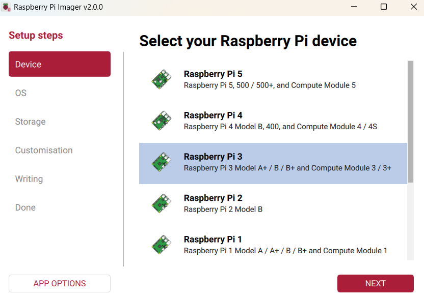
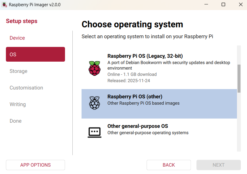
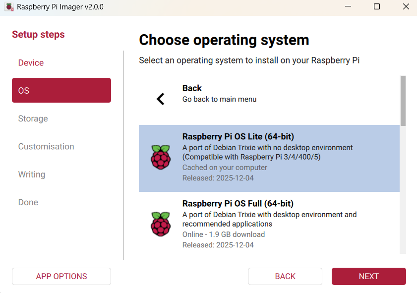
    For the pi3, I used raspberry pi imager:


    and continue through the setup. Be sure to enable SSH as well as enter your wifi connection information and user name and password, then write it to your sd card. I have a USB to SD card adapter, but my laptop also has an SD card slot that works.

once it is written, you can either hook it up to a tv to continue setting it up or connect to it via a ssh client app such as putty or smartty. I used to use putty for everything, but I like smartty a little better because it has a text editor option and allows scp file transfer with its menu plus you can spawn a new terminal or add a second ssh client connection quickly with a side or lower menu bar option.

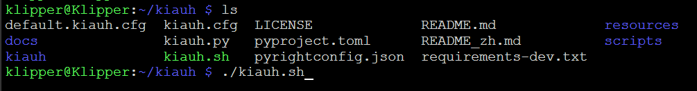
  1. connect to the raspberry pi or linux device via ssh or from the keyboard. it should look something like this, but without all the folders.

update the repositories with

sudo apt update

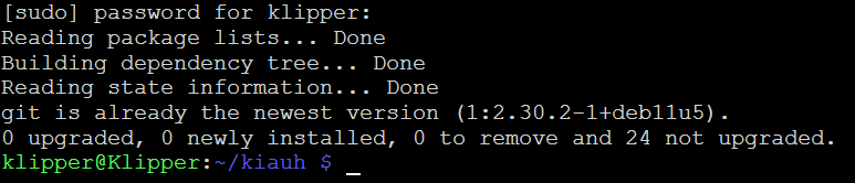
verify you have git installed

sudo apt install git
if it is already installed, it will say something like this. If not it will ask you if you want to install it. press Y

with a git command, clone the kiauh github repository:

git clone GitHub - dw-0/kiauh: Klipper Installation And Update Helper

then move into that folder and run the .sh file


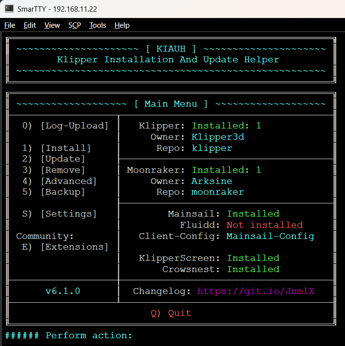
and it will open the kiauh installation menu system:

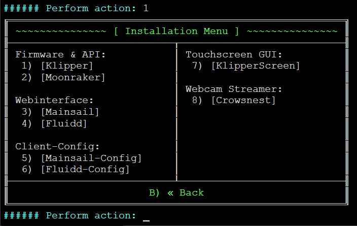
step through the menu by selecting 1

then install 1, 2, 3 and optionally 7 and 8.
Only install 7 if you have a touch screen connected to the raspberry pi. I don’t for my cnc, but you certainly can if you want.
Install 8 if you want to add a camera for remote viewing or timelapse video with the understanding that you should be in the videos it takes, not watching them while it makes them. If you have concerns about that, search fire on this forum.

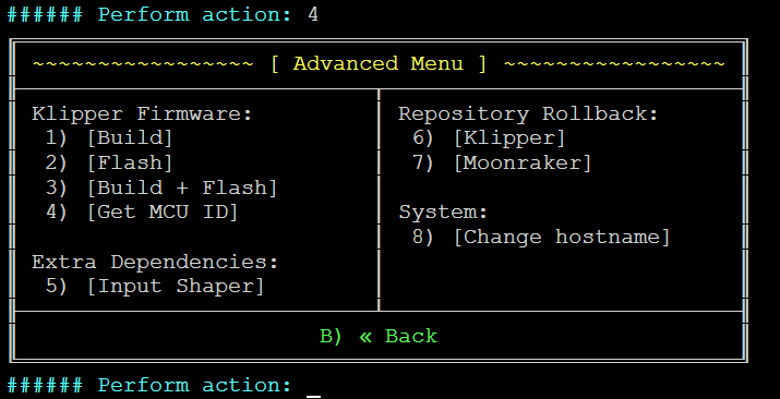
the last thing you need to do in kiauh is make your board firmware. it is an advanced option selected with #4.


if you have a BTT board that flashes with an SD card, you will want to just build. if you have another board like a mega or one that flashes over usb, you can build and flash.
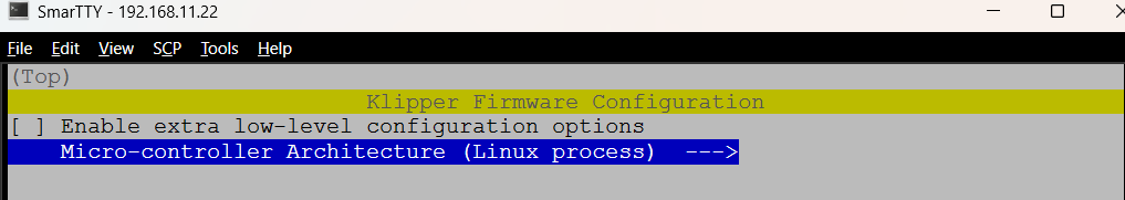
just arrow up/down and press space bar to select…
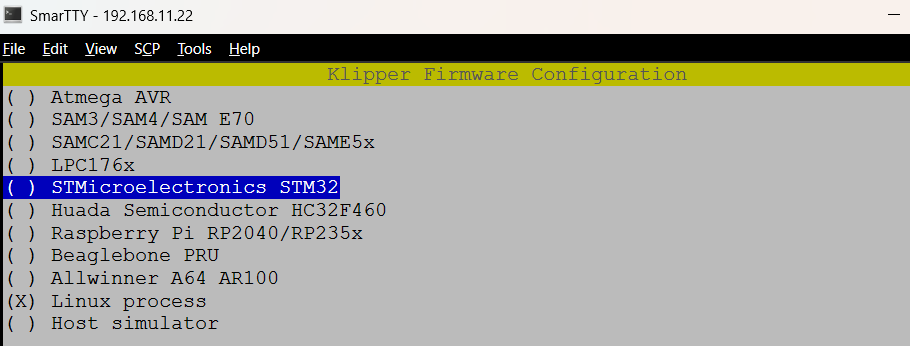
select microcontroller architecture

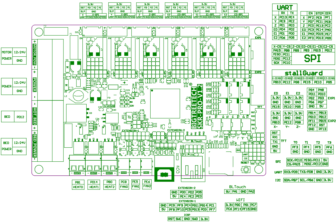
If using a BTT SKR pro 1.2 then select STM32

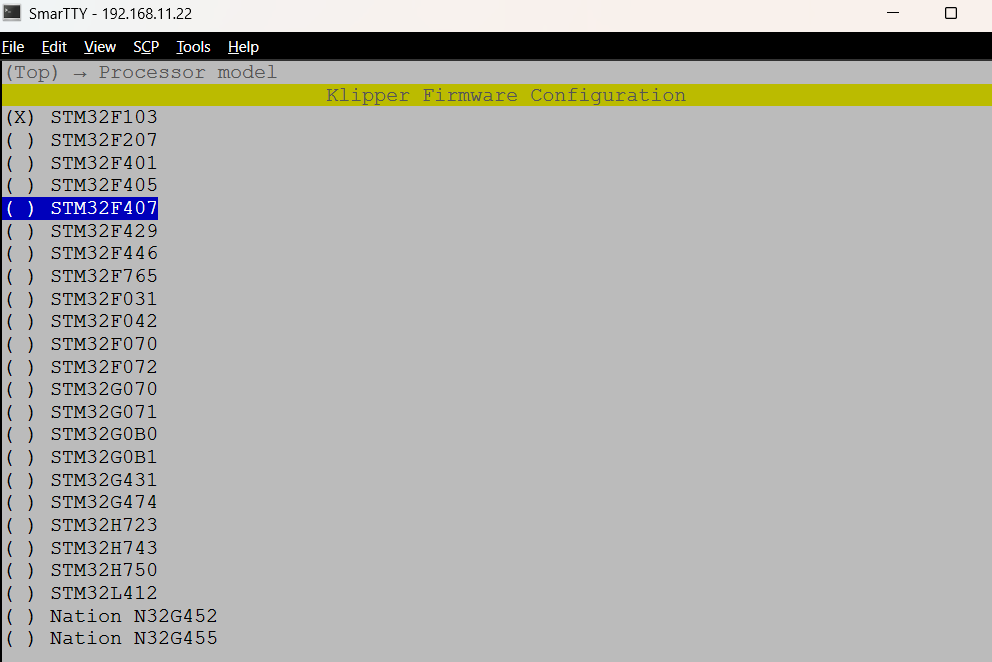
with a magnifying glass, verify the processor label matches the option (should end in 407):

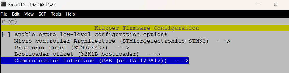
bootloader is 32 and communication interface is usb

you can set the crystal speed to 16 MHz
then press q to back out and it will compile after giving you the option of saving the configuration. Yes and give it a name, or no and it will then start the compile.

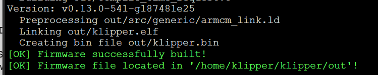
in that compile step, if you don’t see the klipper.bin file name before it says SUCCESSFULLY BUILT! then you need to update klipper and recompile.
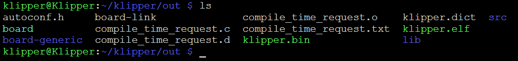
The file can be found here…

using smartty, you can scp transfer it back to your host machine, rename it to FIRMWARE.BIN and flash your controller board with it.

lastly:

while still in ssh or terminal communication with the machine, you can install the v1engineering klipper theme made by @Michael_Melancon. See instructions at the bottom of the page here.

  1. Set up the printer.cfg file
    once you have klipper, moonraker, and mainsail installed, you can finish configuring your system via the web page. since you ssh’d into the system you know the system ip address or if you are at the terminal, you can

ifconfig

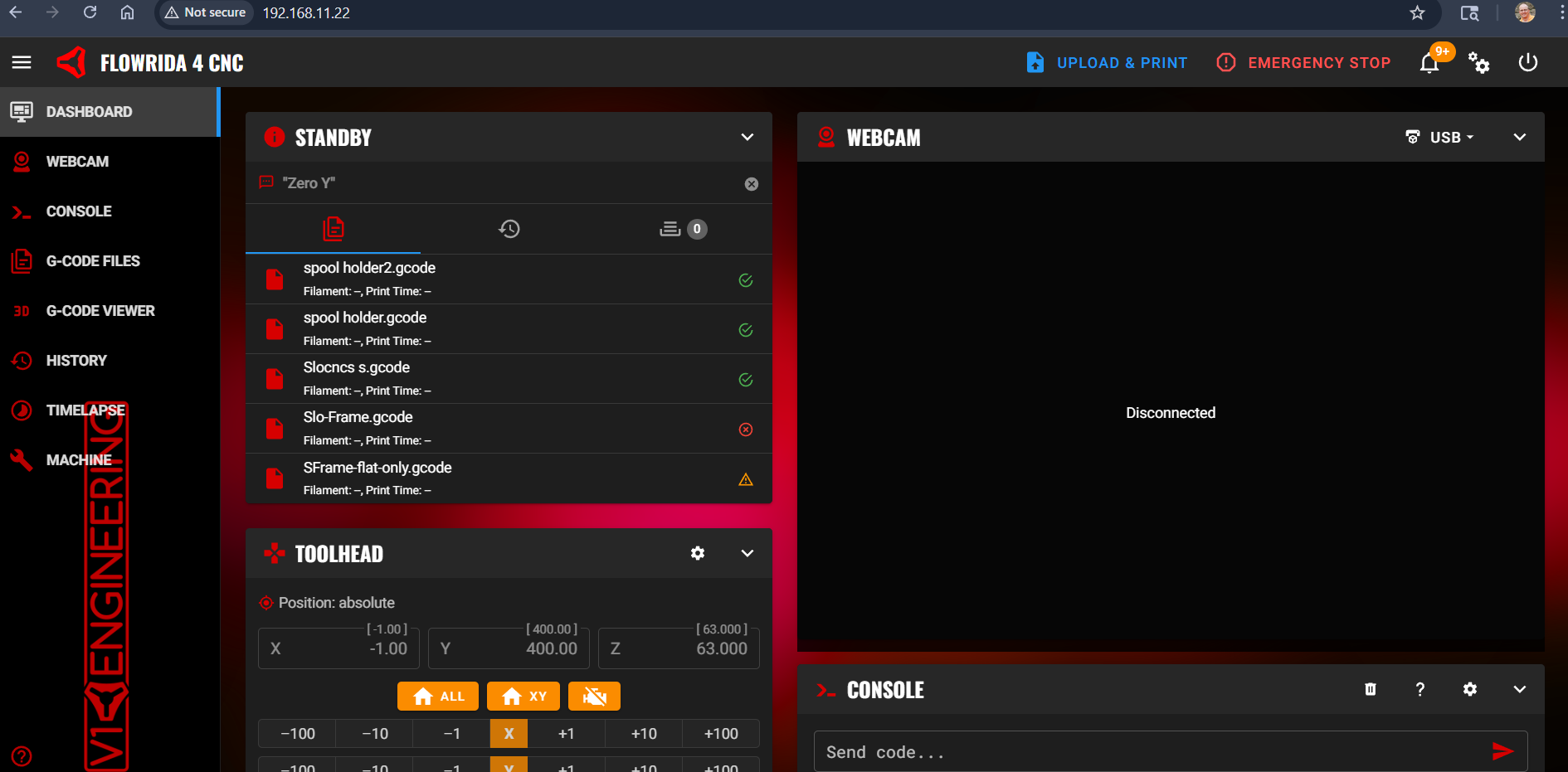
to get the ip address. Simply enter http:// in front of the ip address in your web browser to open the device web page.

This is my cnc web page. The camera stopped working for some reason, but the device still works.


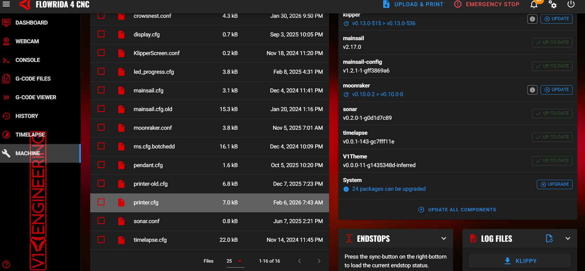
click on machine on the left menu:

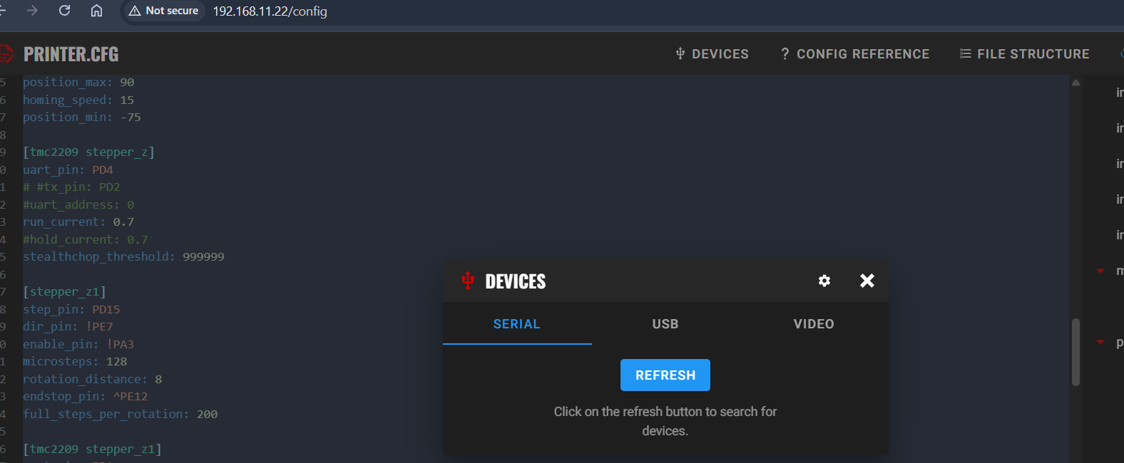
then click on the printer.cfg file. If you device says ERROR, this is ok. It is because your printer.cfg isn’t correct and you don’t even have the USB to your controller plugged in yet. with nothing plugged into the control board, plug it in to the USB with the USB jumpered so it will power on and press the device button at the top of the page:
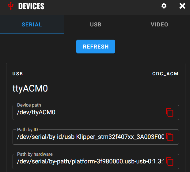

then hit refresh

your device should show up. press the copy button to the right of the “by ID” line and paste it into your cfg text in the [MCU] section similar to below but without the ******

[include mainsail.cfg]

[mcu]
#serial: /dev/serial/by-id/usb-Klipper_stm32f407xx_************************* 
# paste after the : above with your device ID

[printer] 
kinematics: cartesian 
max_velocity: 300 
max_accel: 150 
max_z_velocity: 20 
max_z_accel: 150 
square_corner_velocity: 1 

[gcode_arcs] 
resolution: 1

[pause_resume]

[display_status] 

[idle_timeout]
timeout: 108000 # timeout in seconds (10800 = 30 hours)
   
#####################################################################
# X Stepper Settings
#####################################################################

[stepper_x]
homing_positive_dir: False
step_pin: PE9 
dir_pin: !PF1 
enable_pin: !PF2 
microsteps: 128
homing_retract_dist: 10
rotation_distance: 32
full_steps_per_rotation: 200
endstop_pin: ^PE15 
position_endstop: -5
position_max: 533
position_min: -200
homing_speed: 50.0

[tmc2209 stepper_x]
uart_pin: PC13 
#tx_pin: PE4 
uart_address: 0
run_current: 0.900
# hold_current: 0.90
stealthchop_threshold: 999999

#####################################################################
# Y Stepper Settings
#####################################################################

[stepper_y]
homing_positive_dir: False
step_pin: PE11 
dir_pin: !PE8 
enable_pin: !PD7 
microsteps: 128
rotation_distance: 32
full_steps_per_rotation: 200
endstop_pin: ^PE10 
position_endstop: -19
position_max: 790
position_min: -300
homing_speed: 70.0

[tmc2209 stepper_y]
uart_pin: PE3 
#tx_pin: PE2
run_current: 0.700
# hold_current: 0.70
stealthchop_threshold: 999999

[stepper_y1]
step_pin: PE13 
dir_pin: !PC2 
enable_pin: !PC0 
endstop_pin: ^PG5 
microsteps: 128
rotation_distance: 32
full_steps_per_rotation: 200

[tmc2209 stepper_y1]
uart_pin: PE1 
#tx_pin: PE0
run_current: 0.700
hold_current: 0.700
stealthchop_threshold: 999999

#####################################################################
# Z Stepper Settings
#####################################################################

[stepper_z]
homing_positive_dir: True
homing_retract_dist: 5
step_pin: PE14 
dir_pin: PA0 
enable_pin: !PC3 
microsteps: 128
rotation_distance: 8
endstop_pin: ^PB10 
position_endstop: 63
full_steps_per_rotation: 200
position_max: 90
homing_speed: 15
position_min: -75

[tmc2209 stepper_z]
uart_pin: PD4 
# #tx_pin: PD2 
#uart_address: 0
run_current: 0.7
#hold_current: 0.7
stealthchop_threshold: 999999

[stepper_z1]
step_pin: PD15 
dir_pin: !PE7 
enable_pin: !PA3 
microsteps: 128
rotation_distance: 8
endstop_pin: ^PE12 
full_steps_per_rotation: 200

[tmc2209 stepper_z1]
uart_pin: PD1 
# #tx_pin: PD0 
#uart_address: 2
run_current: 0.7
#hold_current: 0.7
stealthchop_threshold: 999999

#####################################################################
# Sensors
#####################################################################

[temperature_sensor r_pi]
sensor_type: temperature_host
min_temp: 10
max_temp: 100

[temperature_sensor mcu_temp]
sensor_type: temperature_mcu
min_temp: 0
max_temp: 100

#####################################################################
# Misc
#####################################################################

[force_move]
enable_force_move: True
# required for the zeroing macros to work

[virtual_sdcard]
path: ~/printer_data/gcodes

[probe]
pin: !PG8 
x_offset: 0                
y_offset: 0                
z_offset: 0.5              ; plate thickness in mm
speed: 5                   ; probing speed of 5mm/second ideal is <10mm/sec  
samples: 1                 ; number of probes to perform per sample

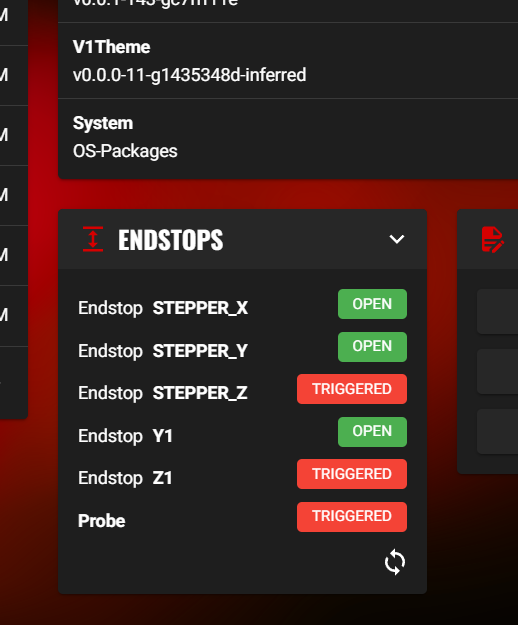
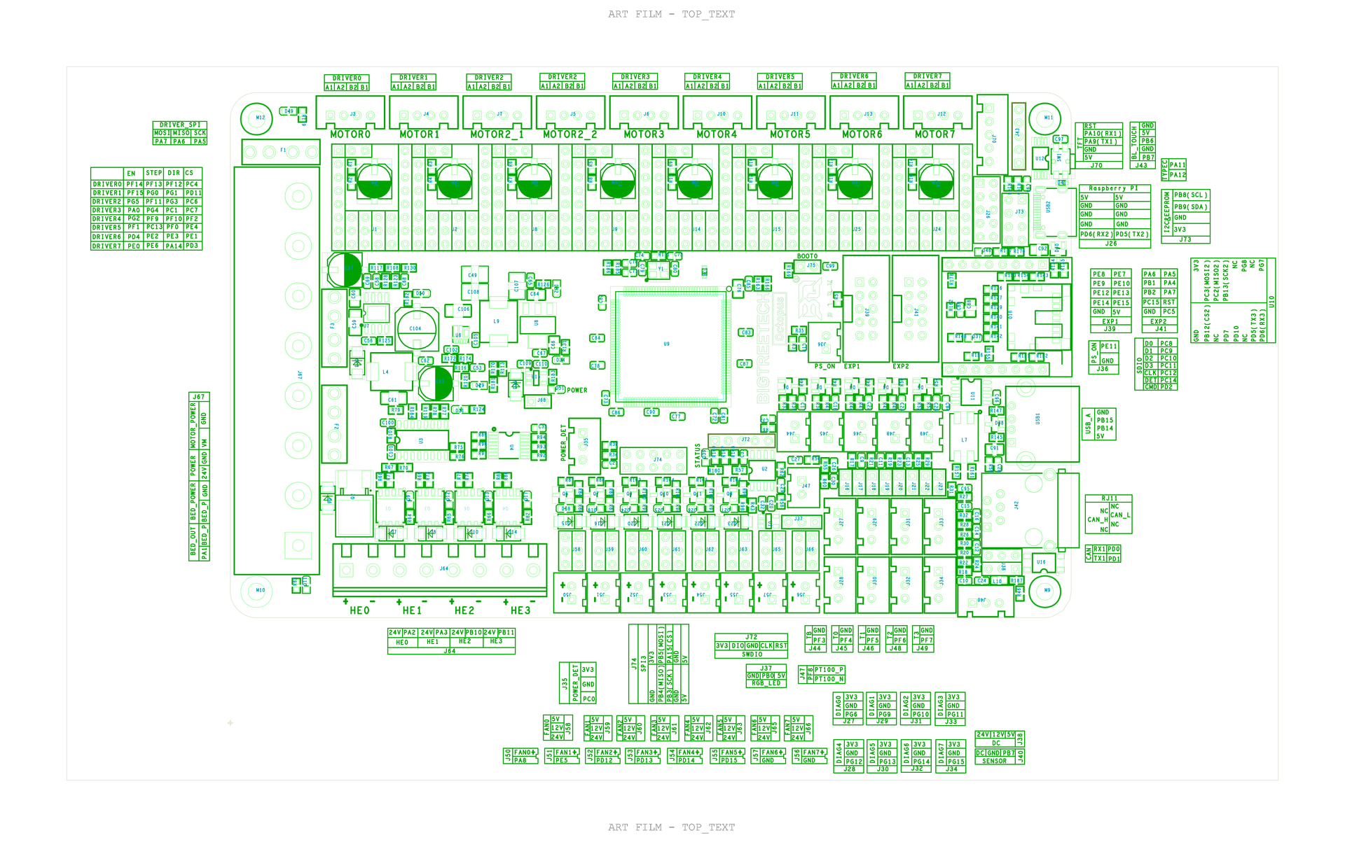
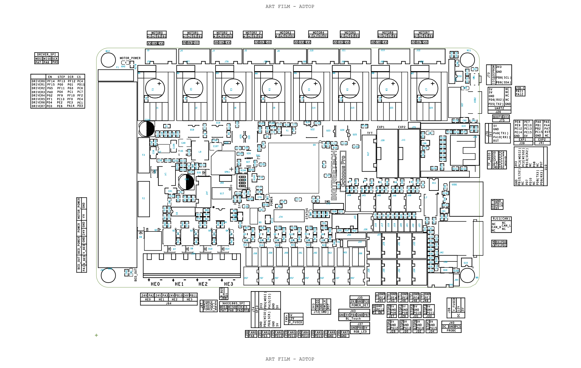
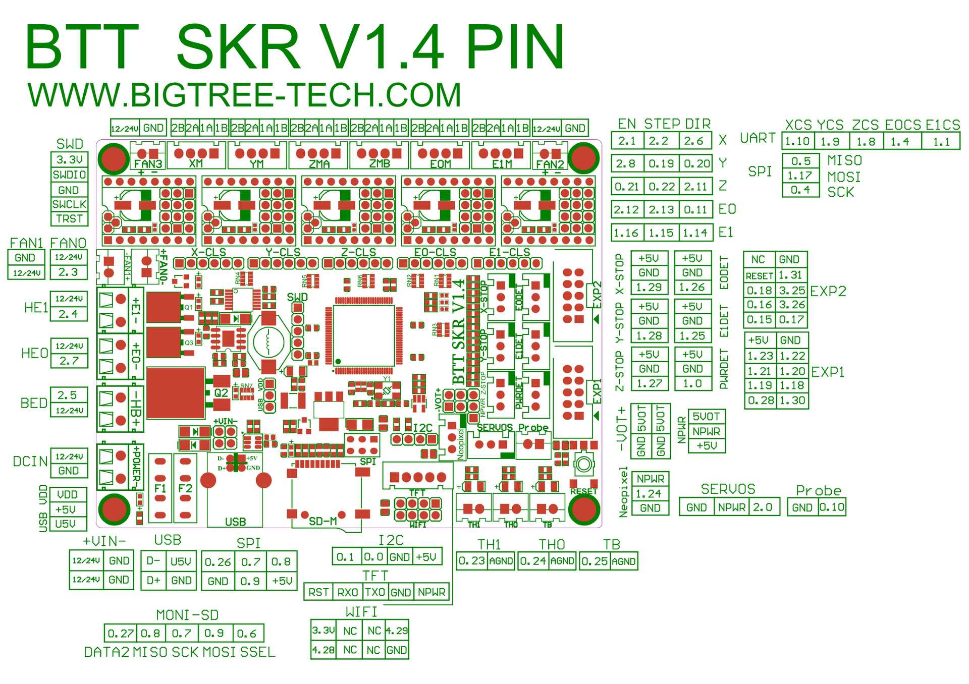
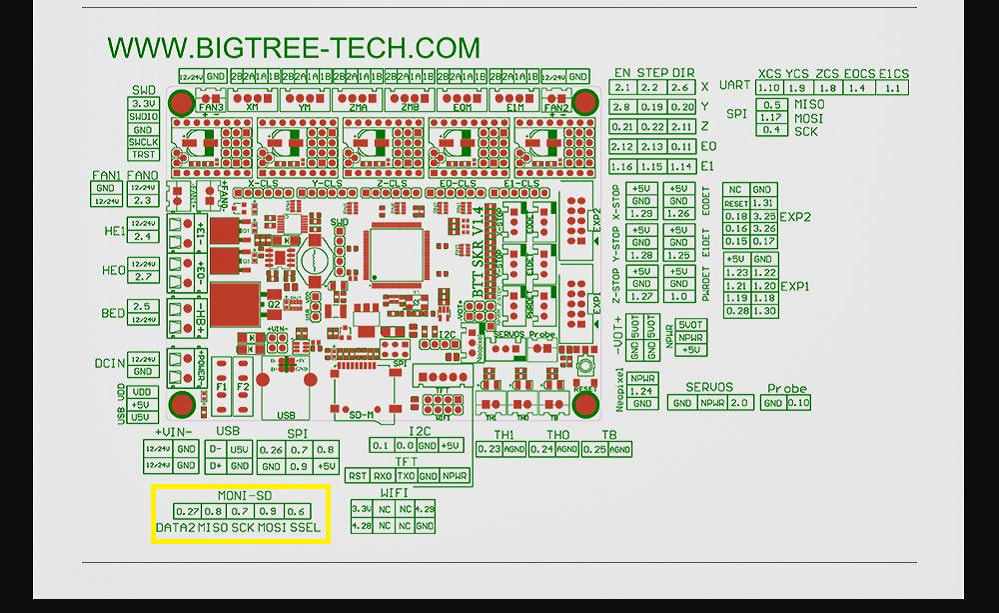
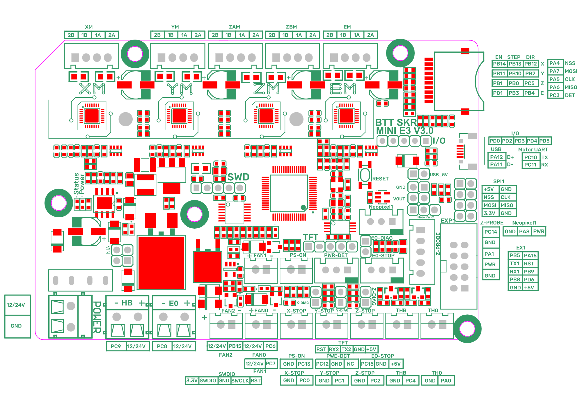
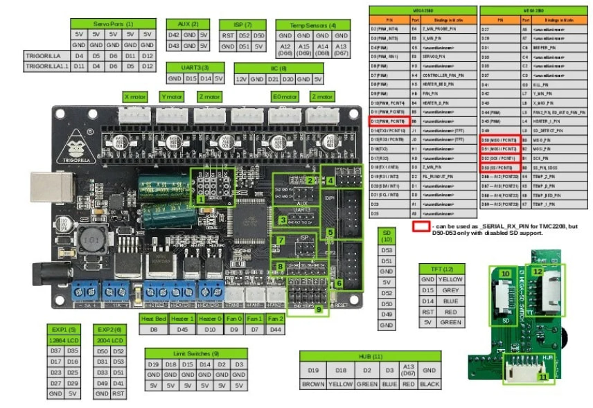
Those are the basic settings. You will need to verify your pins with the pinout board for enstop assignments. You can test the endstops on the web page in the machine section by pressing the refresh arrows


hold them or change them and press refresh to verify they work.
If it reads triggered and it is open, change the pin name to have a ! in front of it or remove the !
If it is the wiring is swapped, you can either change the wires or change the pin assignments and save and restart.

  1. CNC required macros:
    I’ve kind of lost track of the ones that are required. Zero sets the current position to zero. Home runs to the endstops. Probe goes down until it his the plate. Go home goes to the current zero location. I have zero options for x, y, X&Y, z. Most often I use X&Y and use probe for Z zero.
[gcode_macro M0]
gcode:
  {action_respond_info("Initiating Pause from M0 Gcode command")}
  PAUSE
 
[gcode_macro PAUSE]
rename_existing: BASE_PAUSE
gcode:
    # Parameters
    {% set X = params.X|default(230)|float %}
    {% set Y = params.Y|default(230)|float %}
    {% set Z = params.Z|default(10)|float %}
    {% set F = params.F|default(480)|float %}
    {action_respond_info("Saving state of system")}
    SAVE_GCODE_STATE NAME=PAUSE_state
    BASE_PAUSE
 
[gcode_macro CONTINUE_CUT]
gcode:
  {action_respond_info("Resuming cut from last position")}
  RESUME
 
[gcode_macro RESUME]
rename_existing: BASE_RESUME
variable_zhop: 0
variable_etemp: 0
gcode:
    # Parameters
    RESTORE_GCODE_STATE NAME=PAUSE_state MOVE=1
    BASE_RESUME
[gcode_macro GO_HOME]
gcode:
  G90 #Absolute
  G0 Z5
  G0 X0 Y0
[gcode_macro HOME_ALL] 
gcode:
  G28 Z 
  G91
  G0 Z5
  G90
  G28 XY 
  #SET_SKEW XY=1701.8,1700.6875,1200 

[gcode_macro  ZERO_ALL]
gcode:
  M117 "Zero All"
  SET_KINEMATIC_POSITION X=0 Y=0 Z=0

[gcode_macro  ZERO_XY]
gcode:
  M117 "Zero XY"
  SET_KINEMATIC_POSITION X=0 Y=0

[gcode_macro  ZERO_X]
gcode:
  M117 "Zero X"
  SET_KINEMATIC_POSITION X=0

[gcode_macro  ZERO_Y]
gcode:
  M117 "Zero Y"
  SET_KINEMATIC_POSITION Y=0

[gcode_macro  SET_Y]
variable_Y_POS = 0
gcode:
  {% set Y_value = params.Y_POS | default(variable_Y_POS) | float %}
  M117 "Zero Y"
  SET_KINEMATIC_POSITION Y={Y_value}

[gcode_macro  ZERO_Z]
gcode:
  M117 "Zero Z"
  SET_KINEMATIC_POSITION Z=0

[gcode_macro PROBE_Z]
gcode:
  M117 "Probing"
  PROBE
  SET_KINEMATIC_POSITION Z=0.5
  G0 Z10

[gcode_macro START_PRINT]
description: called at the start of a run
gcode:
    HYPERLAPSE ACTION=START # for timelapse based on time, not layer like printing
    SET_FAN_SPEED FAN=tmc_fan SPEED=1 # if you have a fan for motor drivers
    
[gcode_macro START_JOB]
description: cnc is not a print, it is a job, but klipper is for printing
gcode:
    START_PRINT
    
[gcode_macro END_PRINT]
description: called at the end of a run
gcode:
    TIMELAPSE_TAKE_FRAME
    HYPERLAPSE ACTION=STOP
    
    
[gcode_macro END_JOB]
description: called at the end of a run but it isn't a print
gcode:
    END_PRINT
    
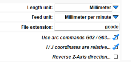
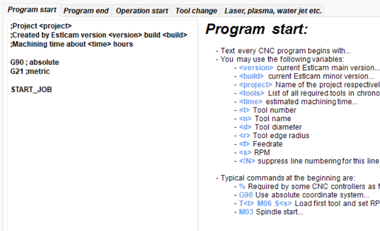
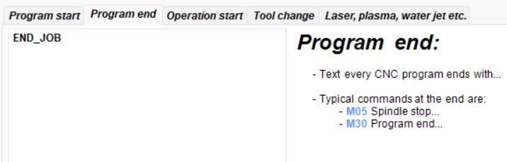
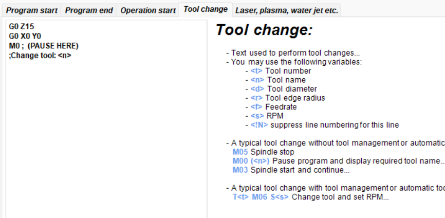
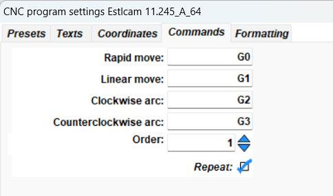
  1. Estlcam postprocessor
    Klipper gcode is most closely related to Marlin. I here are my settings for Estlcam 11:
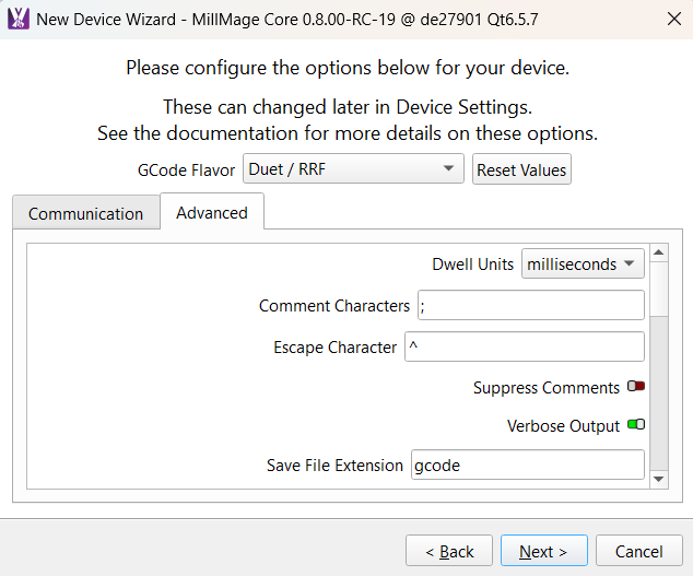


  2. Millmage setup:
    save gcode file and transfer via web gcode file. I just looked and it may have option to control, but I have not tested that yet via millmage RC14. Uploading files for me has worked ok. I’ve milled aluminum with it and it survived.

so that is the basic setup. Some details are not fully explained. Feedback and questions are encouraged. I hope this is useful. I can add info on how to pull data from klipper remotely over the web if desired. I have a wireless pendant for it, but find I most often use the local all-in-one pc nearby because a full featured web page with a wireless mouse is pretty easy to use.

Disclaimer on the macros… they could really be cleaned up, but so far it has worked, so I was going for function over perfection and running a bit fast and loose. I would appreciate any suggestions on how to clean them up if that is your thing.

5 Likes

GOOD STUFF! I bookmarked this.

I have a pile of various old Marlin boards that I’ve been meaning to play with for my repeat as well as on a V1 or V1-esque machine or two.

3 Likes

As a followup, I use google image search when I look for board pinouts labels, but they most often steer me to the reprap firmware site. I’ve done klipper setup on:
octopus

octopus pro

skr pro

skr 1.4

skr 1.4 turbo

mini E3V3

creality 1.4.2 and 4.2.7

  • for the number of boards there are around, I’m surprised it is hard to find, however if you use a default klipper profile for an ender 3, it should have everything mapped in there and you can just rearrange pins
  • I’ve found numerious old ender printers on facebook marketplace and on craigslist for tens of dollars. I’ve used the motors for lowrider4 as well as the controllers (even though only 4) on the lowrider.

trigorilla - a 5 channel board. if you use with tmc2209 chips from BTT say from an SKR board, you have to solder a wire for uart communication.

I have a stack of printed sheets I use when setting up the board pinout. As I wire the board, the printer.cfg file takes shape. If the motor direction is backwards, add or remove the ! before the direction pin label in the .cfg file and simply save and restart.

If you don’t have enough channels, you can plug in a second board and use that, but you have to give it a name and refer to all pins with that name. for example: if your main MCU was for the y axis and the z_mini is for X and z, you might assign the Y and X axis like this:

[mcu]
# for trigorilla board
serial: /dev/serial/by-id/usb-Silicon_Labs_CP2102_USB_to_UART_Bridge_Controller_serial number

[mcu z_mini]
# for BTT minie3v3
serial: /dev/serial/by-id/usb-Klipper_stm32g0b1xx_serial number...

[mcu rpi]
# for GPIO on the raspberry pi
serial: /tmp/klipper_host_mcu


#####################################################################
# X Stepper Settings
#####################################################################
#X axis on core is on miniE3V3 as E0
[stepper_x]
homing_positive_dir: False
step_pin: z_mini:PB3  #for mini e3v3 on channel E0
dir_pin: z_mini:PB4
enable_pin: multi_pin:z_enable # for a z brake that disengages once the x axis activates
microsteps: 128
homing_retract_dist: 10
rotation_distance: 32
full_steps_per_rotation: 200
endstop_pin: ^z_mini:PC15 #D2  ( must be pullup for nc pin)  the ^ makes it a pullup, so it puts voltage on the pin and when the switch activates, it goes high
position_endstop: -5
position_max: 533
position_min: -200
homing_speed: 50.0

[tmc2209 stepper_x]
uart_pin:  z_mini:PC11
#tx_pin: z_mini:PC10
uart_address: 0
run_current: 0.900
# hold_current: 0.90
stealthchop_threshold: 999999

[stepper_y]
homing_positive_dir: False
step_pin: PF6
dir_pin: !PF7
enable_pin: !PF2
microsteps: 32
rotation_distance: 32
full_steps_per_rotation: 200
endstop_pin: ^PJ1 #D14
position_endstop: -19
position_max: 790
position_min: -300
homing_speed: 70.0

[tmc2209 stepper_y]
uart_pin: PE3
run_current: 0.700
hold_current: 0.70
stealthchop_threshold: 999999

[stepper_z]
homing_positive_dir: True
homing_retract_dist: 5
step_pin: z_mini: PB13
dir_pin: z_mini:PB12
enable_pin: multi_pin:z_enable
microsteps: 32
rotation_distance: 8
endstop_pin: ^z_mini:PC0
position_endstop: 63
full_steps_per_rotation: 200
position_max: 90
homing_speed: 15
position_min: -75

[tmc2209 stepper_z]
uart_pin: z_mini:PC11
tx_pin: z_mini:PC10
uart_address: 0
run_current: 0.7
hold_current: 0.7
stealthchop_threshold: 999999

#this segment is not complete as Y1 and Z1 channels are missing... for illustration only

Special note: for axes with 2 or more motors, be sure all motors of the same axis are on the same controller. For example Y and Y1 are together. Z and Z1 are together.

3 Likes

@orob brilliant! Absolute legend. I have read through it once and will try and sort my own out this comming week! Appreciate your time and effort with this thread!

@Sam_Tritto I really hope it is helpful and realize there are a number of nuances and opportunities to get stuck. Please start your thread on with specific questions if you need specific help and we can walk through it together / as a group. Because I didn’t actually set up a controller as part of this writeup, the illustrative pieces may be incomplete as it is more of a brain dump on how I remember doing it. However having set up klipper for several printers and several cnc’s and several other devices that were neither printers nor cnc’s, I know klipper is very flexible and useful and can be made to work. There is a fair amount of testing that will be required to verify each motor direction and endstop and probe are functional, but Klipper has most of those diagnostics available on its control web page and with a config file change and restart of the klipper software (use the “save and restart” button), you should be able to iterate through them without ever needing to reflash and maybe without needing to reboot the pi. Keeping the system and the repositories up to date is also shown in the machine tab and you can update right there as well. There is a lot of power here. There are also cnc macros specifically for klipper you can download, which I did, but I made the ones I use one by one to better understand how they work. You may want to search klipper cnc and check out their repositories for reference or for cloning to implement in your configuration if they suit you.

I’m still iterating on a few things to make my klipper lowrider work better. Just yesterday I ran a simple job. My pause/resume macros need to be tested. Recently I attempted to add a second camera to it because the gopro i have on it isn’t happy or I need another sd card for it… and now both decided to disconnect. I may have static fried the USB or the camera or the config is somehow off from that. There is always more to enhance if you are in to that (I am).

Once you have basic setup, you can add (and I may add additional posts on):

  • timelapse camera
  • WS2812 or similar individually addressable lights or even just tricolor LED’s for under the gantry. These can be run from the raspberry pi directly or from the controller if pins are available.
  • a wireless pendant controller
  • a custom connection to monitor or display information… klipper has a http post/get protocol for remote commands and I recently connected a CYD that a friend gave me for Christmas to klipper.

In changing the cnc from a trigorilla (with 2 bad channels) combined with a Mini E3V3 to an skr pro, I found that the skr pro board doesn’t have a neopixel port like the mini E3V3 did and so the gantry lights that I had working are back on the list of things to do. Time is a premium these days and my “nice to have” projects are greatly delayed in favor of the other things.

1 Like