I am currently building a separate GRBL-based controller which I am going to place below the LR3 table. This requires me to install a cable chain alongside the Y-axis which will contain the wires for the 5 stepper motors and the 5 endstops, plus the touch plate wire. I‘ll keep the vac hose installation as per the original build instructions.
How do people mount the cable chain to the LR3? What is best practice here? I am inclined to fix the chain to the YZ plate, avoiding to put further load on the X-beam. What do people think, is this a good idea?
I am in the same boat and at the moment pondering my options whether I want to try to put the electronics on the lowrider or under the table. I did agree with myself to put it on the Lowrider, but if you come up with a good solution, I might be interested… So I can’t help you but tell you that you are not alone.
Phew, I‘m not alone with my question, that’s good to know My controller plus the drivers are too big to put them on the LR3, though I understand that is the recommended solution …
That’s my rough idea of placing everything. Power supply on the right, then my board, then the drivers on the left. Takes roughly 60cm. I hope that works. Will just screw it to a wooden plate and see how I can fix it on the Lowrider.
That‘ll probably work for you, I‘d guess. But it won’t work for me, my electronics is simply too … heavy . It is an interesting trade-off between adding more weight to the X-beam vs attaching a cable chain.
I thought about adding a couple of relais to operate the vac / the router. I’m also using standard stepper drivers that come with a certain size. It may well be that I could mount these all to my X-beam, but then I would have to protect these elements in a box (well, 1-3 boxes I’d guess) as Marvin showed here: Lowrider-3 aluminum strut plate - #31 by marvinlange
Was initially hoping to use cable drag chain for my LR3. I even printed a bunch of Doug Joseph’s large drag chain links. They look great, but I gave up trying to make the chain work, for now.
For my LR3 on table with ~4’x~2’ cuttable area, ended up being super easy/fast to ziptie/velcro attach wiring along 2-1/2" vac hose resting on the gantry, and to middle of the Y-axis to where Power supply and Vac are located.
Drag chain made sense when was originally planning to run Vac Hose overhead, but that just seemed to complicate and restrict things, was unnecessary overhead for this table size. Running Vac Hose on the gantry, putting Vacuum on the table with Casters enables me to quickly move everything to make space for car/stuff.
Asked about your table size, because might do something different when in larger 4’x8’ full panel mode.
From watching your vid again (btw great job, it helped me a lot while building my LR3!), I can see that you use a controller box attached to the X-beam. This is my configuration today as well, and I agree, it is super easy to use the vac hose and attach the 2 power chords to it.
Now, I’d like to use a separate controller with some additional electronics, and TB6600-like stepper drivers in a box below my table, i.e. I think this all will become too large to mount it to the X-beam of the LR3. I’m not sure whether it’ll work to run 5 stepper motor wires plus 5 endstop wires plus power chords etc via the vac hose, hence the approach to use a cable chain…
I mounted the controller, drivers, a raspberry pi for wireless control on the LR backside. I run gnd, 5V, 12V, 24V through a 4 pin cable. I just let it hang down past the edge. I mounted the power supplies and power control box under the table.
Those TB drivers are not really standard, as much as they are old. There are much smaller, newer drivers that can provide more than enough power for our motors, unless you are doing something like 48V.
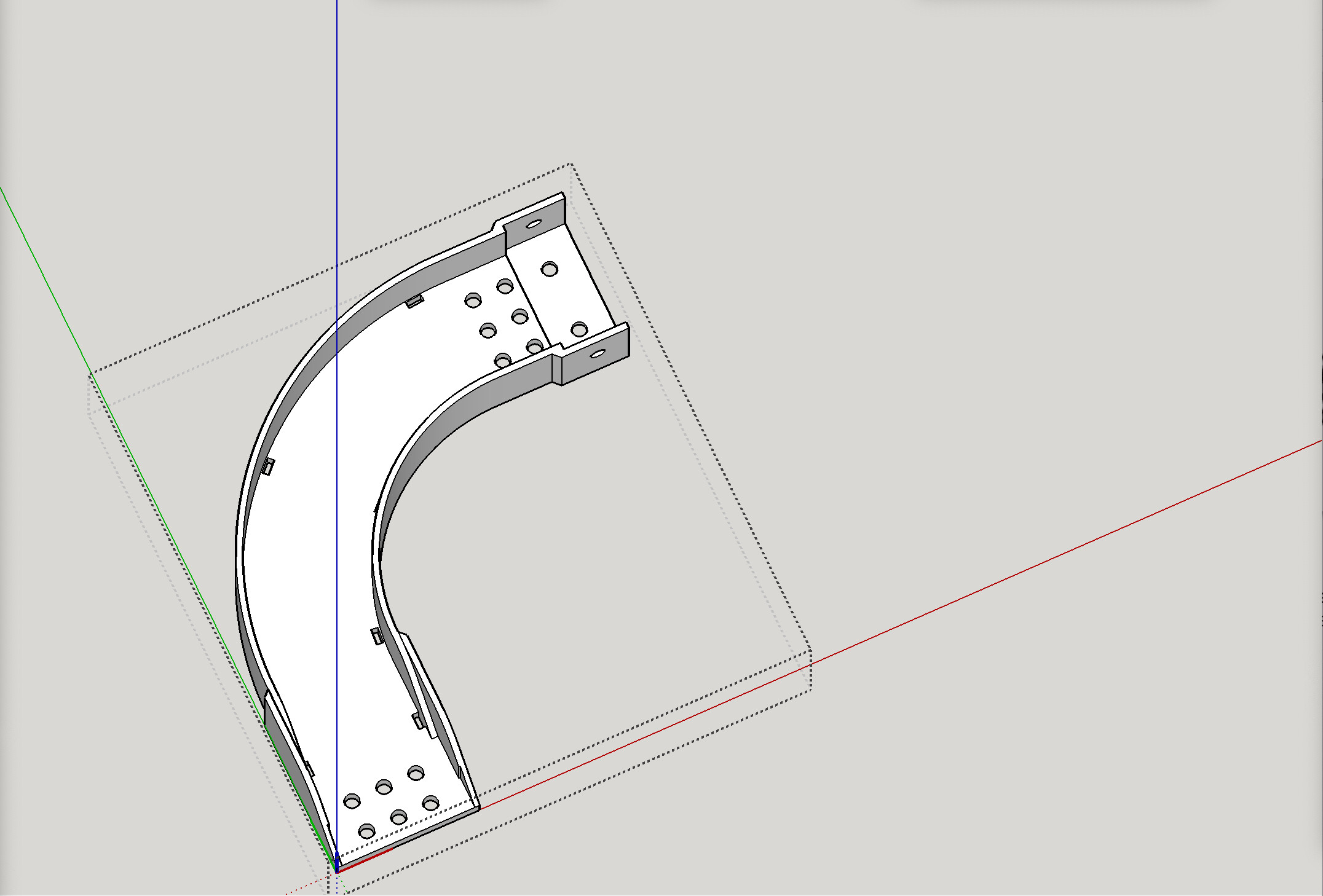
I just recently completed the assembly work on a LR3 that is being used for plasma, that included drag chain for both the X axis and the Y axis, using very large drag chain that I designed and printed. I will try to get you pics and links as well as information about the large 3-D printed 90°-turn raceway that I designed and attached to the gantry to manipulate the cables as they transition from the x-axis to the Y axis. I attached it to parts I designed to replace the hose holders as drag chain holders. See my Printables page for links to some parts already published.
Hi Doug,
thanks very much for this. I’ve seen your parts on Printables, especially your drag chain mount for the LR3 / Plasma remix. It seems to predominantly deal with the cable chain for the X-axis and the transition of the cables from the core / router. So any information about the X/Y transition would be greatly appreciated!
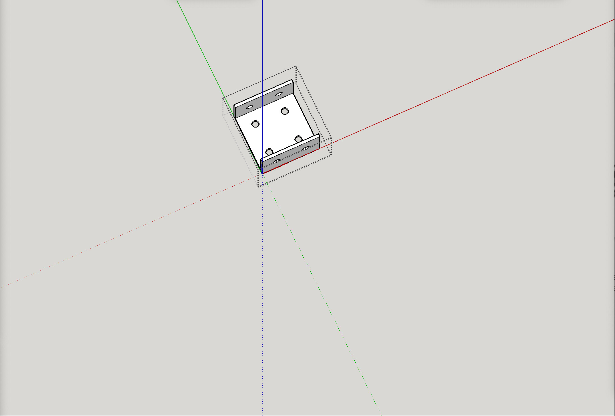
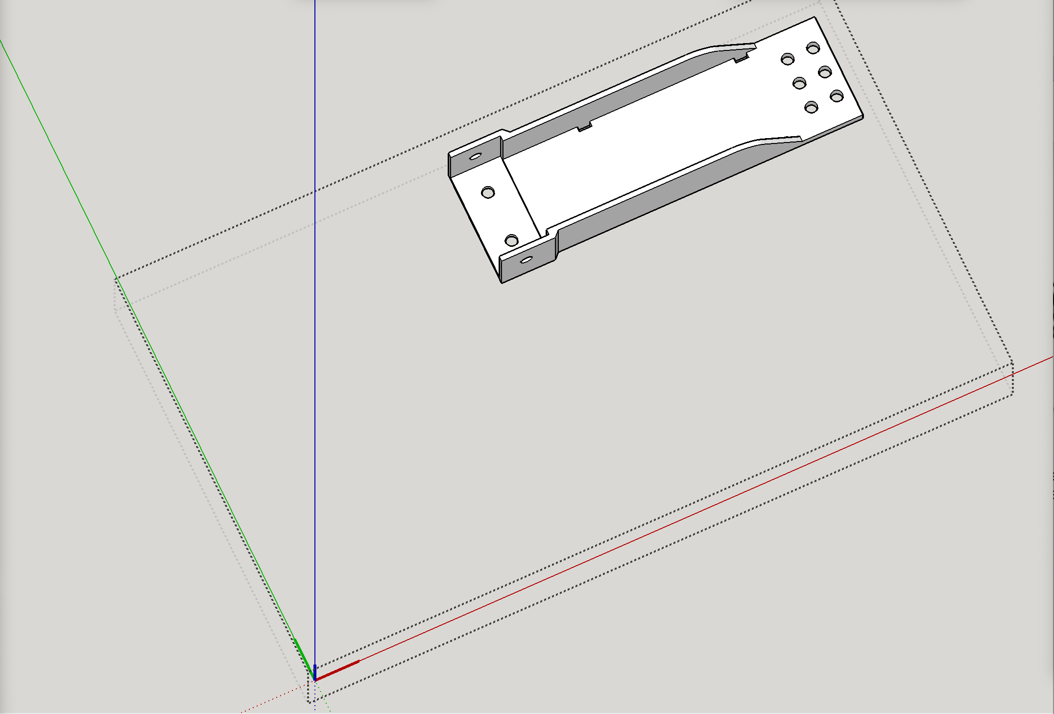
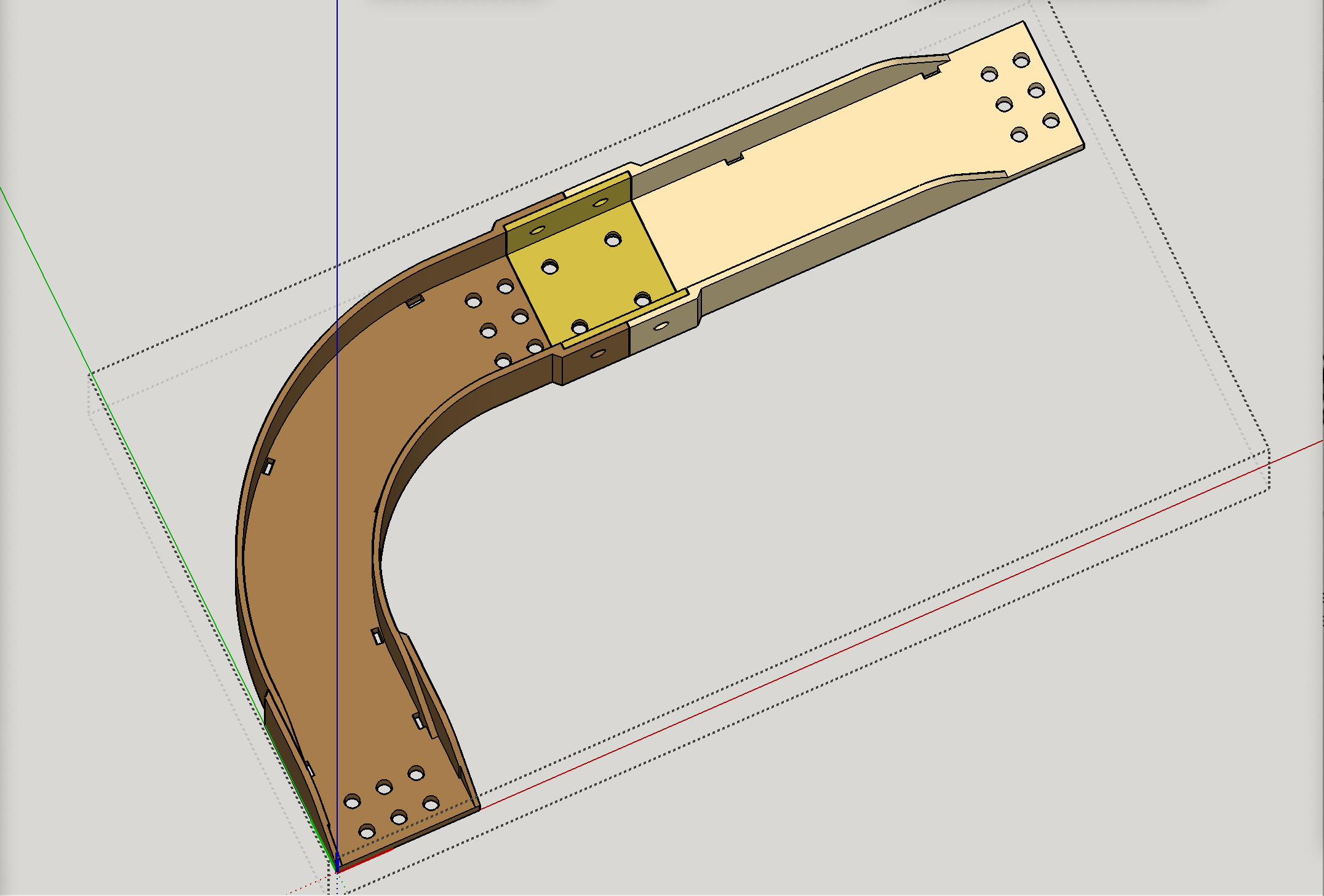
Update: the “Drag Chain 90 raceway curve” is indeed now available on my Patreon page, but that was a huge print, so I also offered a revision of it that’s split into three pieces so it can be accomplished on a normal printer.
Thank you, @DougJoseph. I was already wondering how to print the whole thing on my Prusa. Now you provided the answer!
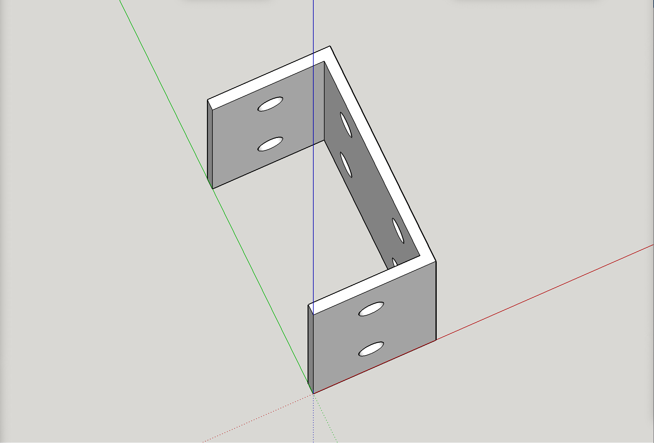
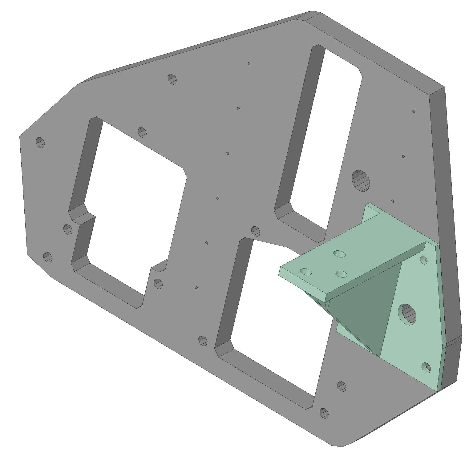
One question though: Your design perfectly integrates with the rest of your LR3 design. I’m by far not a specialist, but aren’t you worried that the raceway would act as a lever and the cable chain would ‘pull’ this lever down, adding load to the Z-axis? Having this in mind, I tried to find an alternative solution, and came back with the following holder for the cable chain mounted on the right YZ-plate:
Your concern is valid, and your solution is surely workable. For my case, the super thick plasma cables are not only weighty, but resistant to bending, and (again my case) clamping them to the YZ plate, which does not move in the Z direction, and then clamping them to the XZ plate, which does move the Z direction, was going to (in my estimation) try too hard at forcing the thick cables to bend too much in a short space. That’s why I tried what I did. Good news for me is, the lever action is not too much, and the Z1 stepper and lead screw are easily handling the load.
 So I can’t help you but tell you that you are not alone.
 My controller plus the drivers are too big to put them on the LR3, though I understand that is the recommended solution …
 . It is an interesting trade-off between adding more weight to the X-beam vs attaching a cable chain.