Also in the good news category for anyone else trying my plasma-based solution with a non-plasma LowRider, their cables will be much thinner and lighter. Since it’s working with my plasma cable, it can surely also work with thinner, lighter cables.
1 Like
Couple quick questions:
I noticed your YZ plate shown seems custom in that the “wheel well” cuts are gone, and the Y motor opening does not have the curve at the bottom. Is this something you designed yourself/remixed?
Also, it seems from the illustration you are planning your wiring to come from the opposite side than mine does. In any case, since the wires/cables have to transition from the “fixed height” mount you’ve shown, to the “adjusting height” mount on the X axis, I would think you would want to allow more lead space for the flexing between Y and X, which would lead me to consider putting the mount you showed toward the “front” of he YZ plate. Mind showing the rest of your plan? Which side is which here?
EDIT: re. the second question
It occurs that you could give lead space on the X axis as opposed to Y, by allowing the first (near side) drag chain holder to be removed, and have your X axis drag chain not start until at least the second brace.
1 Like
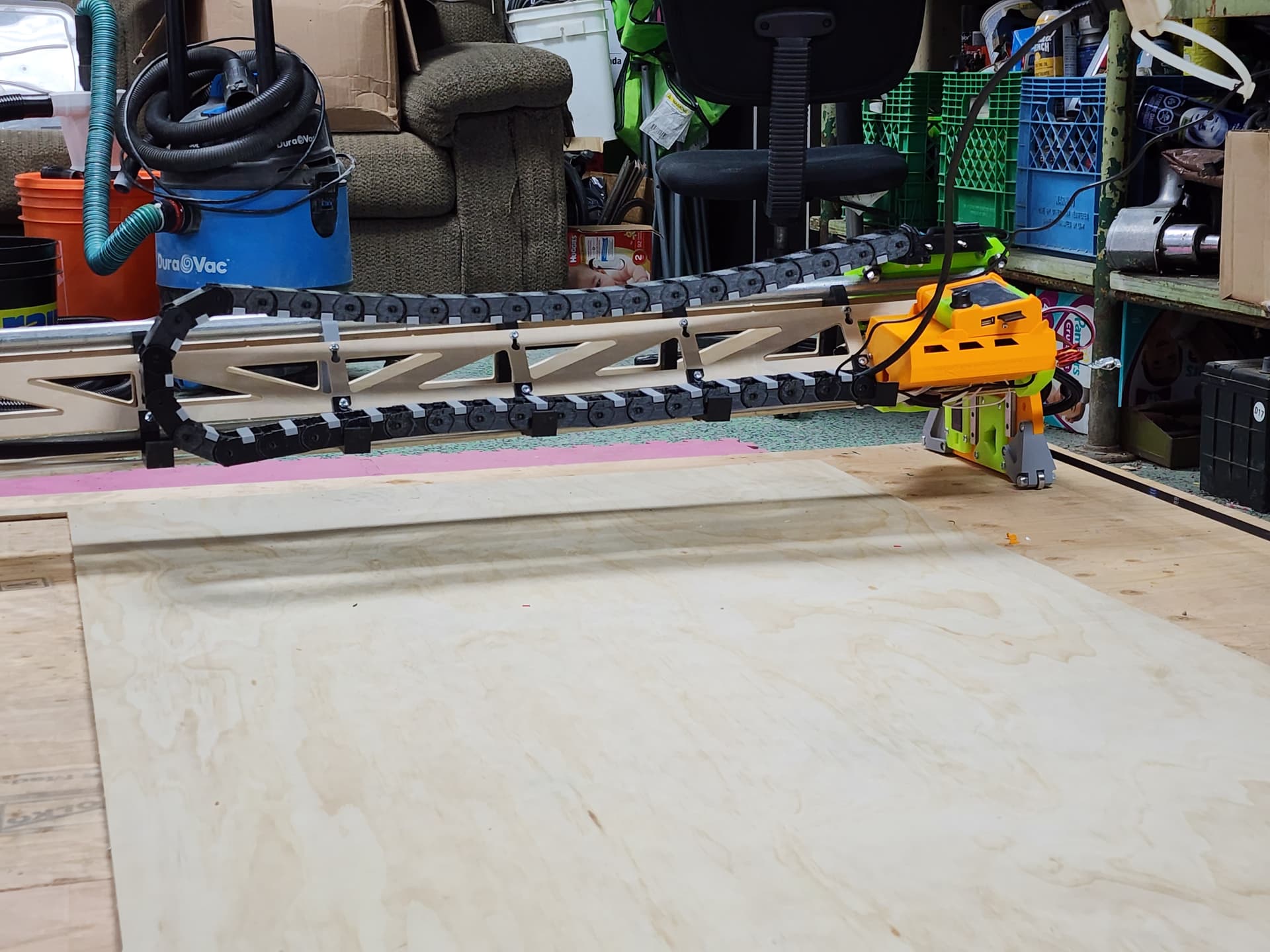
Apologies, I think something went wrong with the STL import. I use a standard LR3 design, so nothing special about my YZ plate:
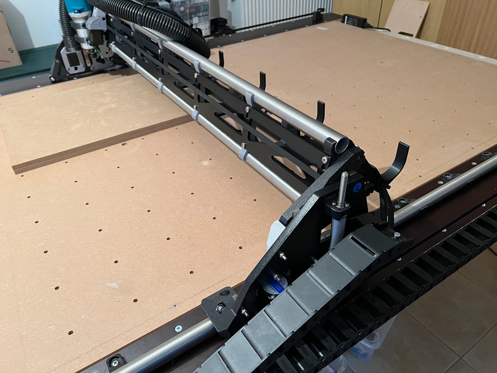
In the above pictures the drag chain is not yet functional. I only attached it to demonstrate the to-be. The cables are still wired as per the V1 assembly instructions.
Also, it seems from the illustration you are planning your wiring to come from the opposite side than mine does.
Correct. It will come from the right, which in my case is Y2/Z2.
…which would lead me to consider putting the mount you showed toward the “front” of he YZ plate. Mind showing the rest of your plan? Which side is which here?
I hope with the picture it is clearer now. Or would you move the drag chain mount anywhere else?
It occurs that you could give lead space on the X axis as opposed to Y, by allowing the first (near side) drag chain holder to be removed, and have your X axis drag chain not start until at least the second brace.
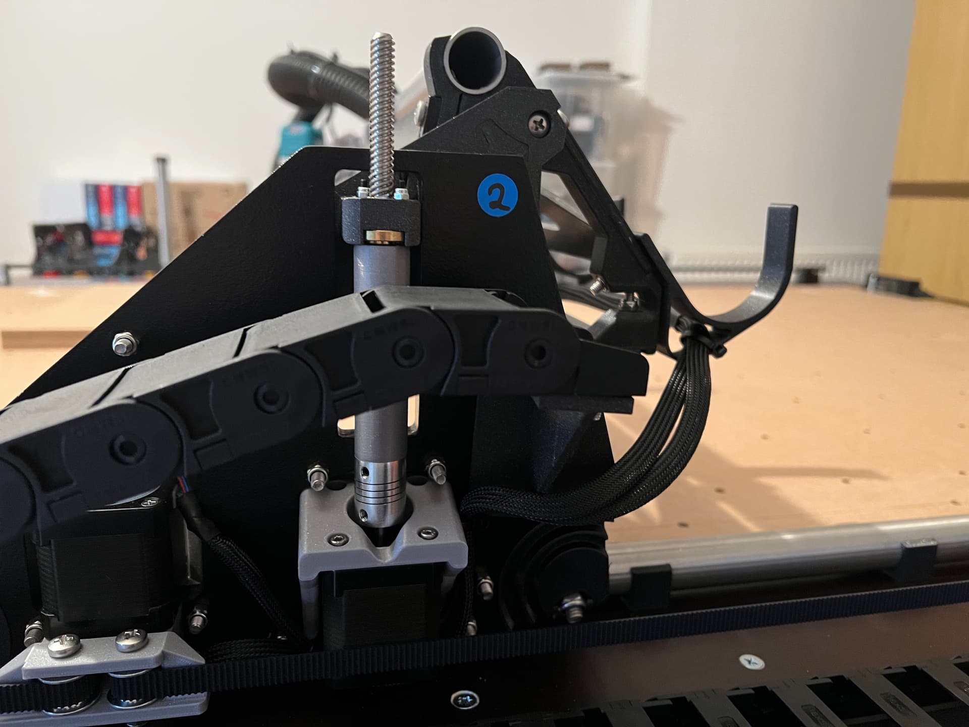
I agree, the first brace could go. I’m using the vac hose as dragchain for the power chord, the X stepper and the endstop/touch plate; so no X axis drag chain needed.
Not sure whether this setup is optimal?
1 Like
If you keep the first (nearest) hose hanger, then if you move the new mount/holder to the left (as compared to what’s shown in this image) perhaps to the other side of the lead screw, if could give space for the wires to transition up/down:

However, if you leave it right there, but remove that first hose hanger, it might be possible to have the wires use that space for the transition. It might depend on if they are wrapped in some cable wrap, or whatever to help them navigate the turn without getting snagged on something!
1 Like
It also just occurred to me that since I am on “Dan’s extra tall YZ plate” my vertical range of motion is more than normal, and so you may have less transition needed than I do!
2 Likes
Sharp looking machine!
1 Like
It also just occurred to me that since I am on “Dan’s extra tall YZ plate” my vertical range of motion is more than normal, and so you may have less transition needed than I do!
Good point, I guess there is plenty of space for the cable transition, even if I kept the first hose hanger. I’ll test this scenario in the next few days.
1 Like
Sharp looking machine!
Thank you very much ![]()
1 Like
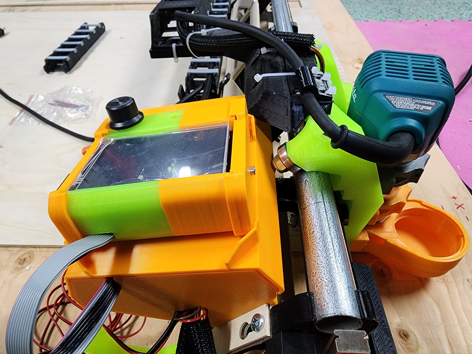
Ran into a small issue, I think if I cut the corner off in fusion or my slicer and re print I’ll be ok.
Or print another electronics case, but modding the bracket is less filament
1 Like
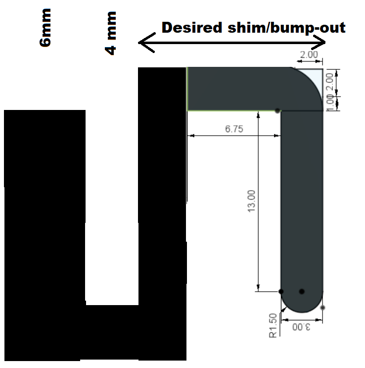
Bracket is hitting the case? Would S shaped shim help to push out case from being hit by the bracket, and avoid having to reprint existing parts? Shim mounts to Strut, Case mounts to Shim. Something like…
1 Like
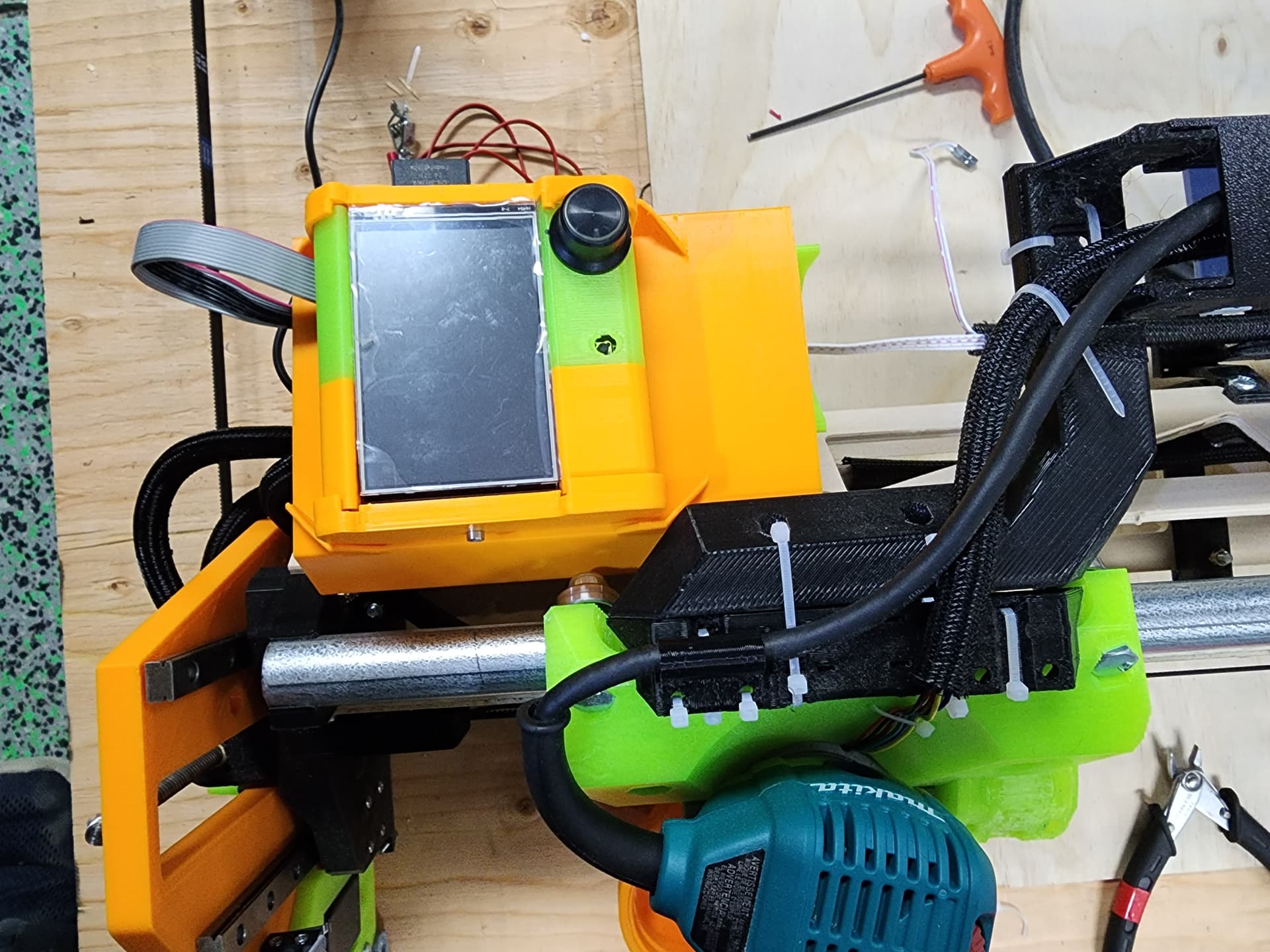
It probably would yes, I did try putting it in the lower triangle but I won’t fit ( if I remove or angle the corner of the “hook” it might)
1 Like
Crap. I appreciate you sharing your build journey. Unfortunately for me, your situation just made me realize, many days ago, I probably should’ve Shimmed my existing case away from the Strut to help resolve a Vac Hose and Core collision issue I’ve been facing.
Instead of keeping it simple, am deep down an enclosure redesign rabbit hole… Too invested to walk away. Keep thinking I know Fusion 360, then YT folks like Products Design Online and Noe Ruiz at Adafruit give me knowledge, and a reality check of my own ability. Much to learn.
1 Like
I’d Love to see the case your working on.
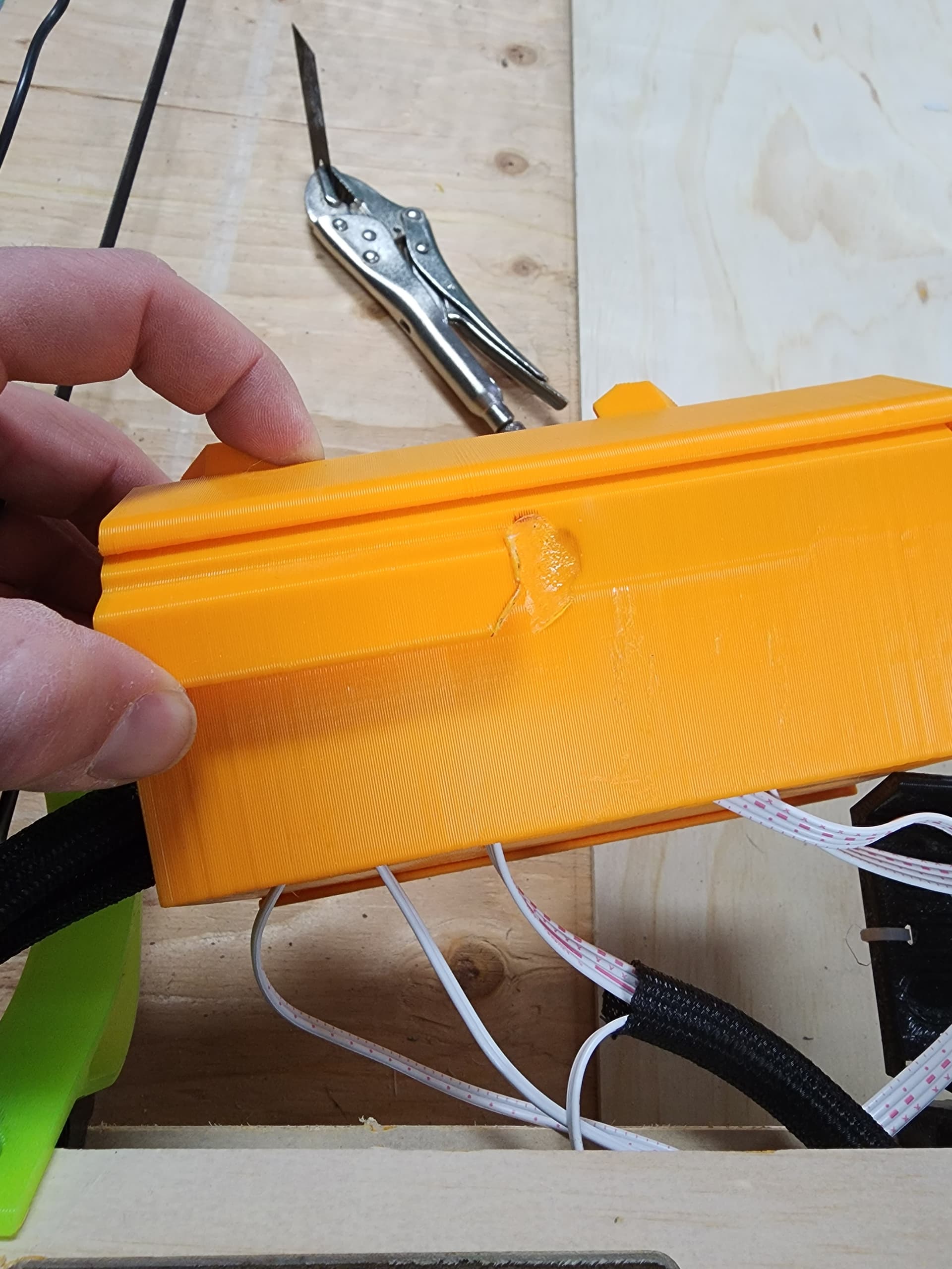
I ended up heating up a box cutter blade and modding the hook on my case, it just fit’s on the bottom triangle now, takes a little pressure to hook on but I’m happy with it.
3 Likes
Mind sharing this bracket? It’s exactly what I am looking for!
I use the ones Doung shared: Printables I have an aluminium rail installed on them.
Looks like this: Der Froschkönig - Lowrider 3 in Oldenburg, Germany - #73 by Tokoloshe
1 Like
Will share later on printables as I am travelling today/tomorrow
Isn’t that the X-axis though? I was referring to Christian’s model of the Y-axis dragchain.
Thank you very much! ![]() I appreciate that a lot!
I appreciate that a lot!
Oh yeah, sorry. My Y has got a drag chain as well. ![]()
So, this is my first model on Printables, I hope I got it right…
1 Like