The repeatability with a pen should be very good. Often it is so good that you can’t tell that it’s been traced twice.
It’s also possible that the friction is not uniform over the entire workspace. Also the stiffness is sometimes mildly nonuniform, if the load is supported almost entirely by one belt when near the edge, or if it’s split evenly across two belts when closer to the middle. But this effect should be small unless a motor is shorted.
So depending how you’ve arranged the experiment, it’s possible that the variability you’re seeing is not representative of the repeatability of the machine and you are instead observing nonuniformity over the workspace. The nonuniformity “should” be small enough to ignore, but if the system defies explanation, a test that controls for uniformity could narrow it down, proving either that it is true non-repeatability or that it’s something else.
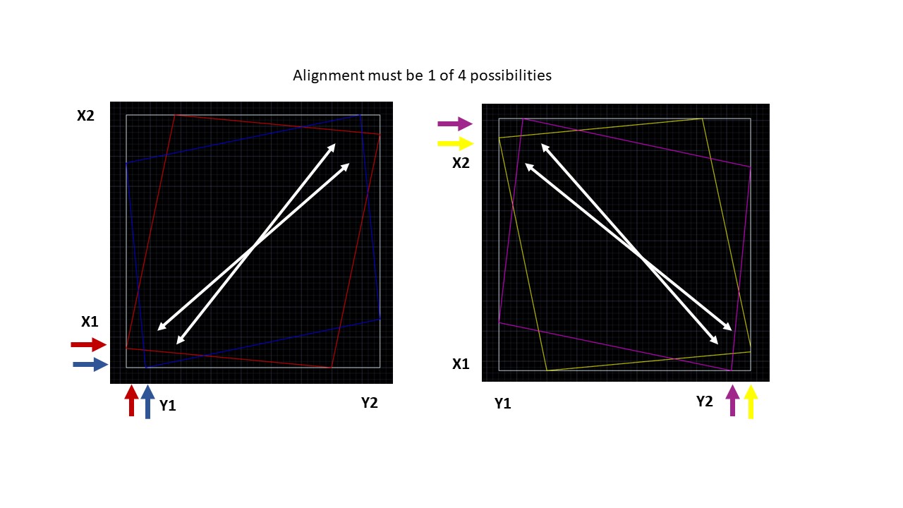
Let me explain my squaring routine in more detail so you understand my limitations. Unlike the drawing I posed earlier the attached picture shows the 4 conditions you can have with an unsquare bed. Very exaggerated of course. Hopefully you can see the colors. 2 of these result in the SW (origin) to NE diagonal being longer and 2 result in the NW/SE diagonal being longer.
Set X1 and X2 limit switches so engagement happens very close to same time. Repeat the same for Y1/Y2.
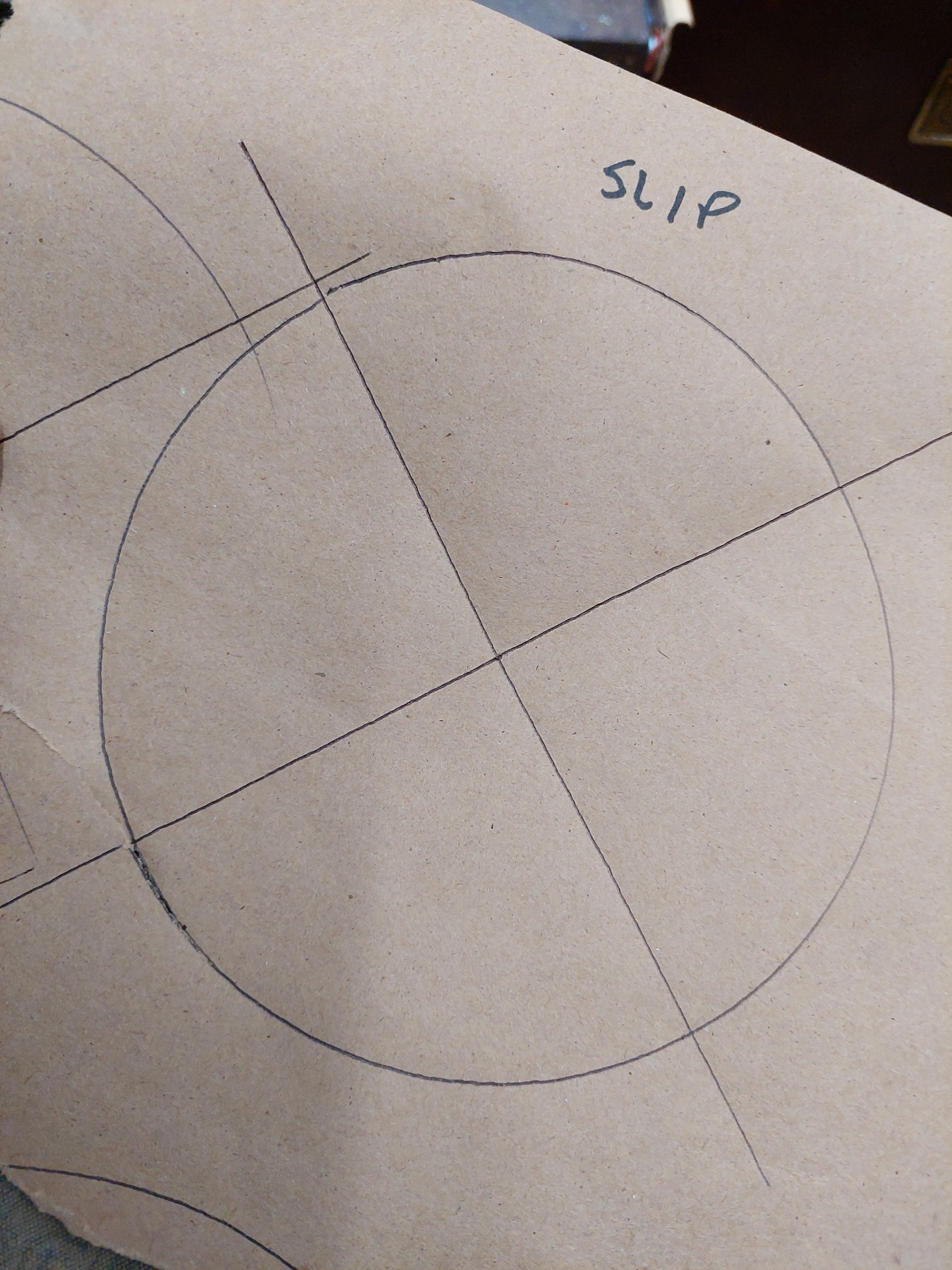
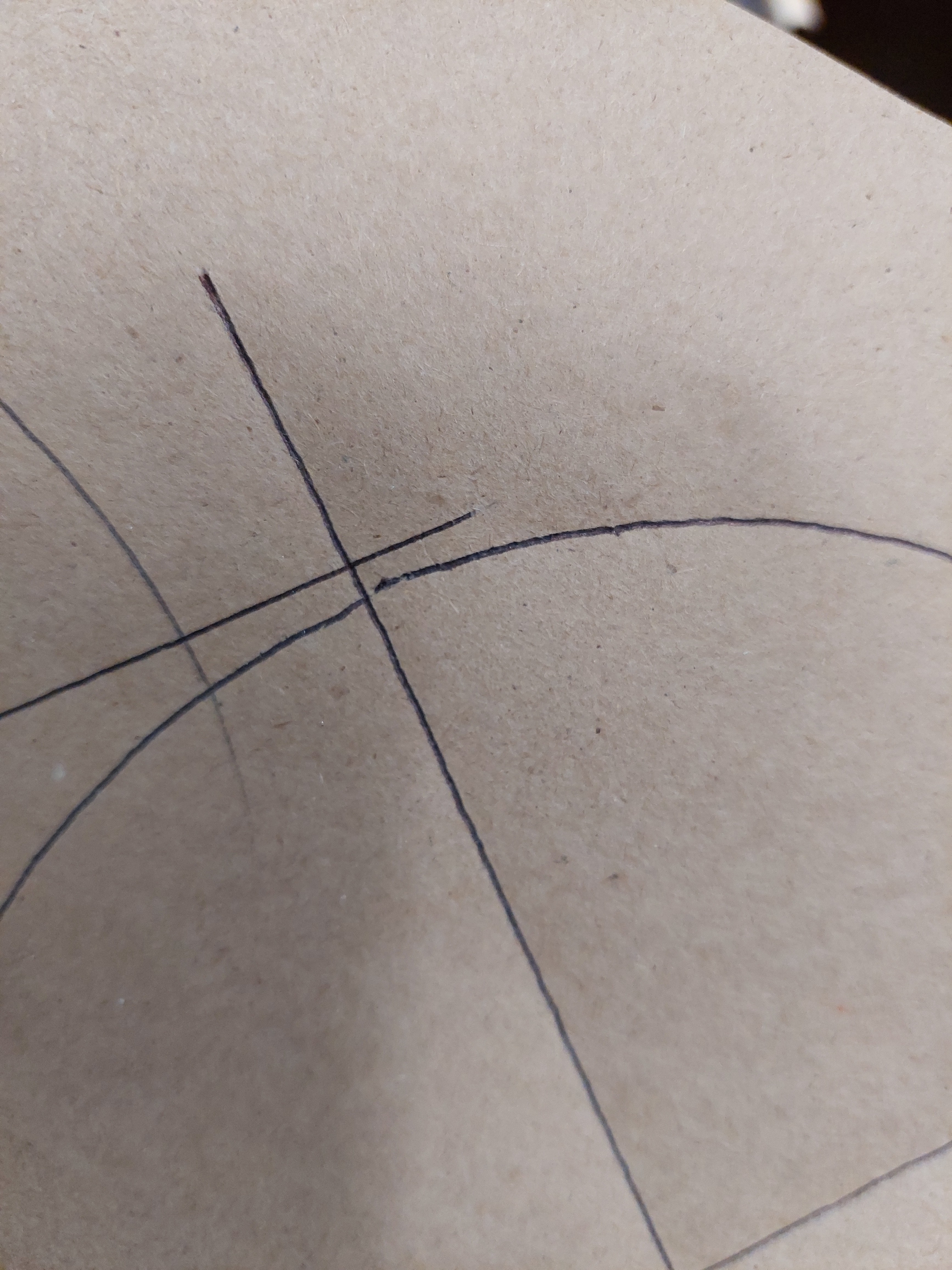
Draw a box, circle with diagonal cross hairs, just dots on the diagonals, or touch down on a scale. I have tried all 4 and I am drawing circles now just for speed.
Determine which diagonal is longer. Due to the fact M666 codes only affect X1 and Y1 offsets, SW(origin) to NE diagonal must be longest before entering M666 gcodes to adjust. If NW/SE diagonal is longer, either X1 or Y1 limit switch will need to move back behind X2/Y2 to manually adjust the offset. Move either X1 or Y1 switch back about 1mm and redraw diagonals. Repeat until SW(origin) to NE diagonal is longest.
Begin entering M666 gcodes to offset one either X or Y offset. Bump home before drawing. As you increase offset each time you draw a diagonal the SW/NE diagonal should get shorter and the NW/SE diagonal should get longer until you pass the square point and then NW/SE diagonal becomes longer than SE/NW. Then you can keep adjusting in smaller increments until satisfied with alignment.
So this routine works perfect for me every time with predictable results until I get into 1/10mm adjustments on the offsets. I am currently drawing 150mm circles with a ball point pen cartridge in the router collet. I measure these under magnification with a caliper. I try to measure to the center of line which is maybe accurate to .25mm. When I try to make the final adjustments to get the diagonal difference less than .4-.5mm, the results become unpredictable. The same thing happens when measuring with other methods and you begin chasing something you can not find.
2- I still think you should spend the extra few seconds and get the full resolution of a square. You are getting 150mm diagonals with your circle, when you could be getting 212mm with a square, ~30% more accurate.
3- M666 can go negative as far as I know, you are just limited by your switches throw…you can have it zero to a few mm ahead if you didn’t want to move a hardstops. Lots of ways to do things here.
Took the machine down and squared the legs up. Also leveled a bit to the table it is sitting on so the spoil board will be a little more level. Moved the end stops to the trucks and routed all the harness again.
I began drawing 150mm circles again to dial it in and they seemed OK but then I got a flat spot with a drawn circle. I would have thought the paper slipped if I didn’t experience this before.
So that was a ringing bell and I did what everyone should do before troubleshooting. I sat down and stared at the machine. Seems like it must be the grub screws. So I started playing with the trucks and the pully did not move, but the truck did a little and springs back. So at that point I thought it must be belt tension. They did not look too loose like I have had in the past, but I think they were just a little looser than what I normally run. So I cranked them down until I could pluck them like a guitar string. Adjusted all 4 to the same tune.
So then I set about squaring everything up again. And the 150mm circles came right in. So I switched to squaring on 400mm box corners with the 2 machinist scales. AND IT CAME RIGHT IN AS I ADJUSTED OFFESTS. Square to 0.2mm on a 400mm square. And repeated a couple times. So now I am getting excited.
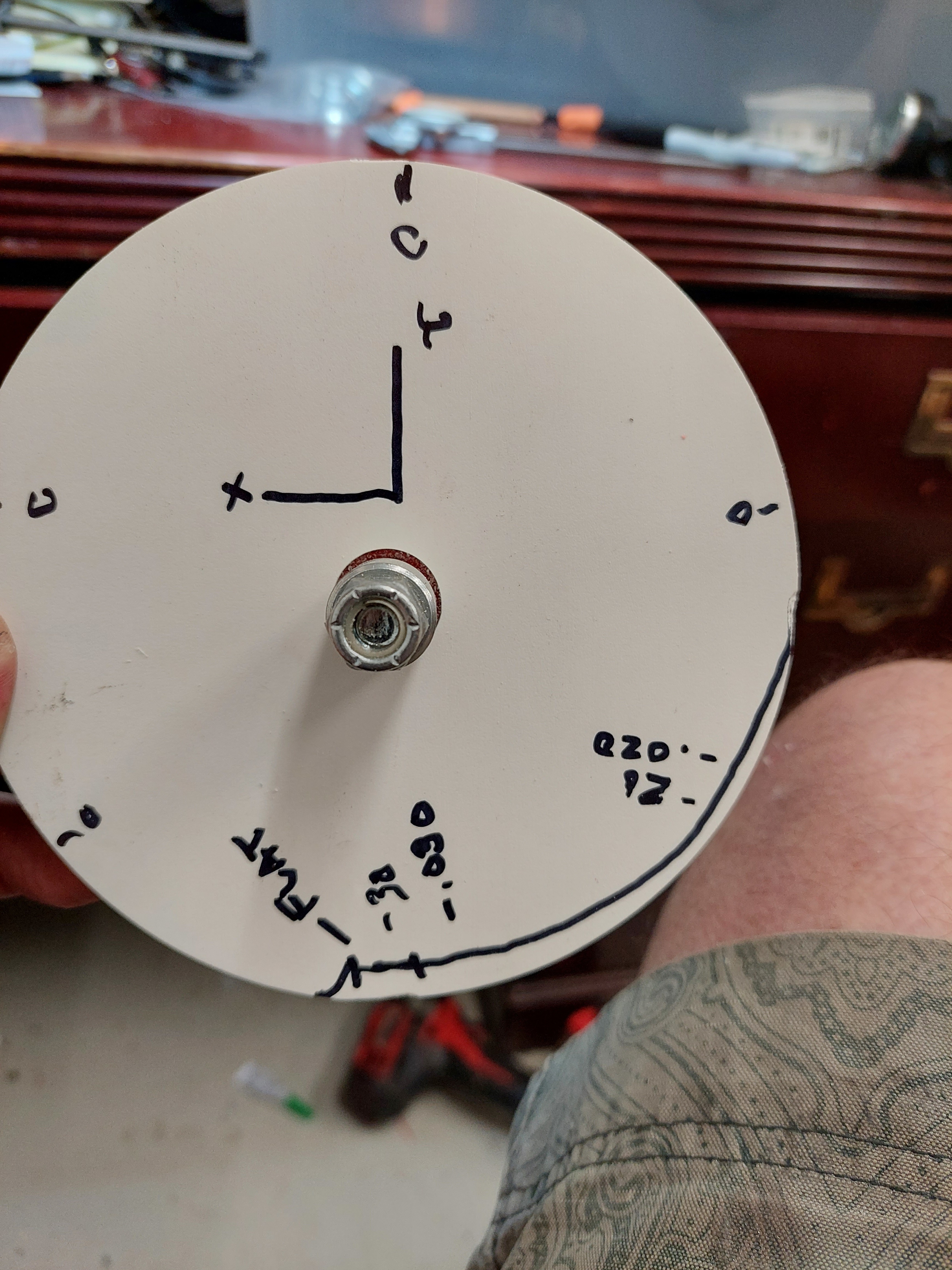
So I decided to cut a 150mm circle and try the runout test. I only have enough material to cut 2 more circles. Strangly enough the circle was perfect for 3/4 the diameter but still had the damn flat spot.
At that point I packed up ready to call it a night. As I pa ked up I thought this must be a loose grub screw again. So I went and checked each of the trucks and found one of the truck rail clamps was loose from my big reset operation. I tightened it up and decided to cut the last circle i have material for.
The last circle I cut came in with an out of roundness of 0.010" or 0.25mm. There was no definite diagonal offset apparent, but the low point was still where the tool enters and exits at due south and there is a very little flat spot there. Even so, that is pretty damn good!
So next time I am will get some more material to cut and check all the clearances and bearing tension again. I really hope what I have at this point is repeatable, but based on the 30-40 squares I ran, I think it it is. Each offset change gave a predictable move down to the 0.2mm on a 395mm square which is as low as I can read.
The flat spot from plunging should disappear with the finishing pass, since there should be very little load on the tool. What sort of settings are you running, Depth of cut, feedrate, total depth, rpm, type of tool, number of flutes. Maybe you are just hammering your setup.
Try going even lighter on the pen pressure. I can see the indent on the paper. That will absolutely cause the mismatch.
I can not find the exact post, but I am sure Barry posted it. At Mrrf we ran a few of these on top of each other even after homing and there are absolutely no flaws whatsoever, MRRF 2019 - #32 by ohbaby This even has the screw heads drawn in with a 0.3mm fine tip felt marker. Incredible detail and absolutely no deviation with several passes, and no indents on the paper.
If you are having the same problem try moving to a different spot on your work surface, there is a flaw somewhere on a rail or your belt is broken. This is not normal at all. Plucked tight belts can break the strands and give a stretched spot, that is the reason we don’t run steel belts, they break and it is hard to find the stretched spot.
Either way, pen or no pen, once I tightened up the belts things got real repeatable. I exaggerated a little, they are not super duper tight, but they are definitely tighter than I have ever run them. I probably only needed to tighten them 2 turns but I went over and did 3 turns. I have needed to tighten at least 6 times since I built the machine. They seem to stretch when ever I crash the trucks which happens sometimes when experimenting or forget something laying on the table.
I think at this point, alignment is no longer an issue. It is aligned as best as visually possible. The offset is 0.59mm, so I actually set it to the 100th of a mm. I could distinguish the diagonals change with a .02mm change in offset with the scales. Those are extreemly predictable no load movements to do this.
I think the next phase is looking at reasons a cut circle varies from the alignment. After I check all the bearings I will try some cuts with a heavier finishing cut to see if I can remove the low spot. I am still convinced cutting a circle and measuring runout is the ultamate test. But it is the very last thing to look at.
On the experiential side, I may have come up with an idea to “auto” align the system. I have a couple high grade string pots I think I could rig up to measure travel. I think I could direct measure the diagonals with it, and with some data collection could actually graph the results. Maybe even map gcode coordinates to actual movement. A lot of possibilities here. As I mentioned in an earlier post, I would really like to square up my machine in under 5 minutes and being able to verify alignment before an important cut would be golden.
That should not happen. I am assuming your belts might have broken. The threads inside are either fiberglass or kevlar, once tensioned they should not really move. I have not touched mine in a long time. The steppers should easily skip steps and cause no harm to the system, I have them at the low end of what is needed in terms of current.
Hopefully you did just start too loose and didn’t break a thread.
NEW PROBLEM. My X1 endstop is triggered at all times. Even when it is unplugged from board. I cannot understand how there could be a closed circuit with no cable connected to board. If I unplug the other endstops they show triggered as expected. I reflashed the board 2X with no change. Any ideas?
They are all NC. I even found that command in the Marlin firmware. They all trigger when open. Except X1_min. It shows triggered (closed) at all times even with no cable/endstops connected. I pulled out the board and all the pins look good and secure.
I spoke too soon. The M119 showed X1 triggered. I plugged back in the endstop switch. Then X1 showed open. All good. I did a home command, all good. I powered down, stuck my board back into the case and reconnected USB. Then power up and X1 is triggered again. Even when disconnected from Zmax.
When I put the board back in the case I also plugged back in the cooling fan… I turned off my cooling fan that blows across the board. And it works again???