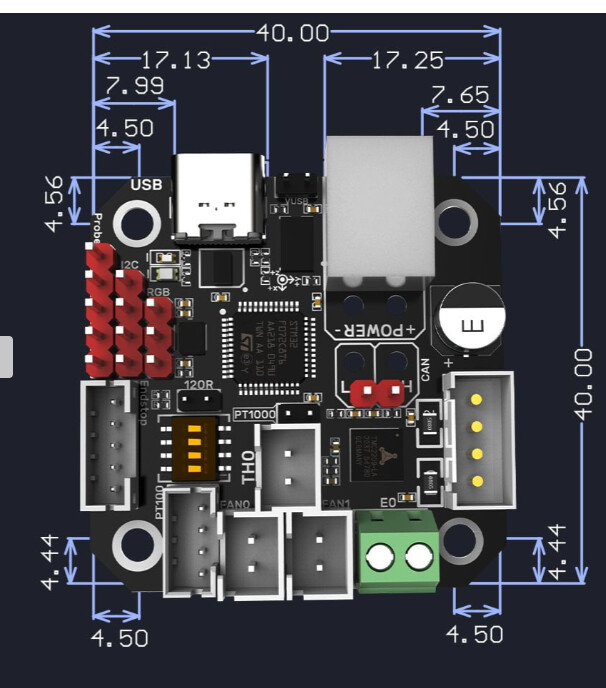
That is the square one (40x40mm), and the triangle (50x35mm?).
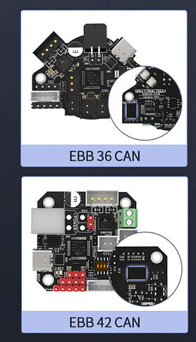
Using EBB36, at the time, seemed like most MP3DP Makers using CAN went with that.
Noticed @gpagnozzi used EBB42 for his build when I was reviewing what everyone was Making https://forum.v1e.com/t/mp3dp-v4-azas-build/37251#bigmp3dp-v4-v1e-community-builds-buildersbig-35
1 Like
As far as I know they are basically identical boards. The EBB36 is designed to mount to a nema14 and the EBB42 is designed to mount to a nema17 being the only difference between the 2
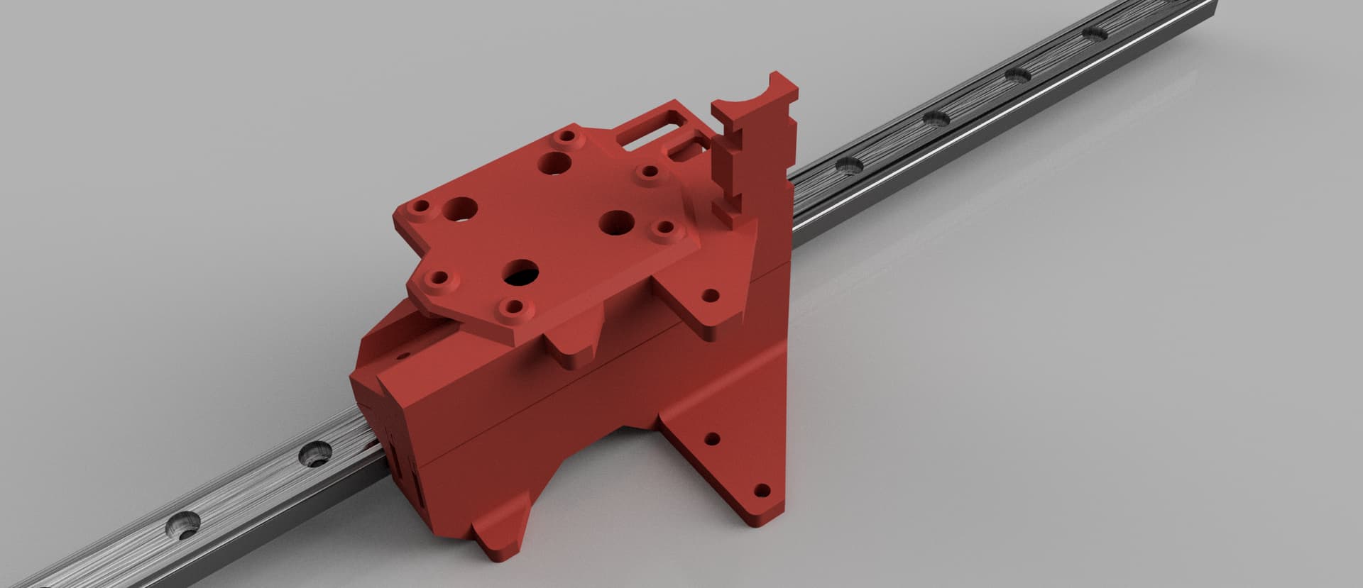
Okay, looks like I just need another test print of the core after all the fiddling.
Has optional ebb36/42 mount, hemera or H2, and a umbilical holder(not sure about this one until I print it.).
So XY needs a X rail nut holder (tnuts), and a Y endstop. After those we finally get to move on to the Z axis.
I will add a note here The XY has 1.5-3mm “extra travel” on all sides. We just got lucky. I know for a couple of you this is not enough. I would rather cut it this close (maybe even lose a mm or two) than have all machines with an extra 12-15mm on all sides. If you want all sorts of extra room for some reason you will just need to add 25+mm to your bed size, and pay attention to the bed mounting holes, should be no big deal. Same goes with adding things to the sides or back just add more room
H2 & EBB
3 Likes
I think the XY is close enough, I might even buy some XY rails…I highly recommend no one else do that, just in case something changes.
C’mon, Ryan… You’ve gotta know that some of us will buy parts on pure speculation at this point. ![]()
![]()
![]()
Normally that would totally be me, but I already spent my hobby money this paycheque. (And have another ZenXY printing now to use that Bart Dring board with. Ikea glass shelves next time I’m on that side of town.)
2 Likes
Flat deck, or vertical mount for EBB and strain relief so flimsy CAN wire runs alongside PTFE?
If using EBB36, then, seems like having CAN cable connector oriented same direction as PTFE might help with tying them together (i.e. pointing up, instead of flat on deck) ?
Asking because the leftovers stranded Cat5E cable in my CAN Bus setup is flimsy, relied on PTFE to help support the wire.
Are you planning to run PTFE and CAN power+signal wires next to each other, to back of frame, or using dragchains, or something else?
Does/will CAN Bus wire have strain relief on the Core?
For my v4, was planning to have strain relief for CAN connector cable up top.
Running a piece of filament along with your can wire helps a ton. But I do think it’s going to have to be done a little differently with this style mount. You will need the last little bit of your cable flimsy to go from where the strain relief is to where the canbus plugs in since they aren’t in line.
The wires need something to hold them 1.5" to the upright wire holder?
I am not using CAN, I plan on running my wires to the back and the ptfe to the side pointed out the front.
I am not fully understanding what you are asking for in that post.
I am not sure what I am missing here. Why are you guys worried about a USB cable being bent up to the wire mount?
No usb cable. It’s a cable with a twisted pair for can high and low and also 24v ±
That seems even easier to kinda fold over and run back? Do you guys have a picture of how you are currently doing it, so I can understand what to look out for.
Not any good ones. None on the v4 but I have these 2 of the E5+
I’ll see if Carmen can send me some to post since I won’t be back to take any till the 29th lol
Edit: As soon as I said it was for You she jumped right to it LOL…
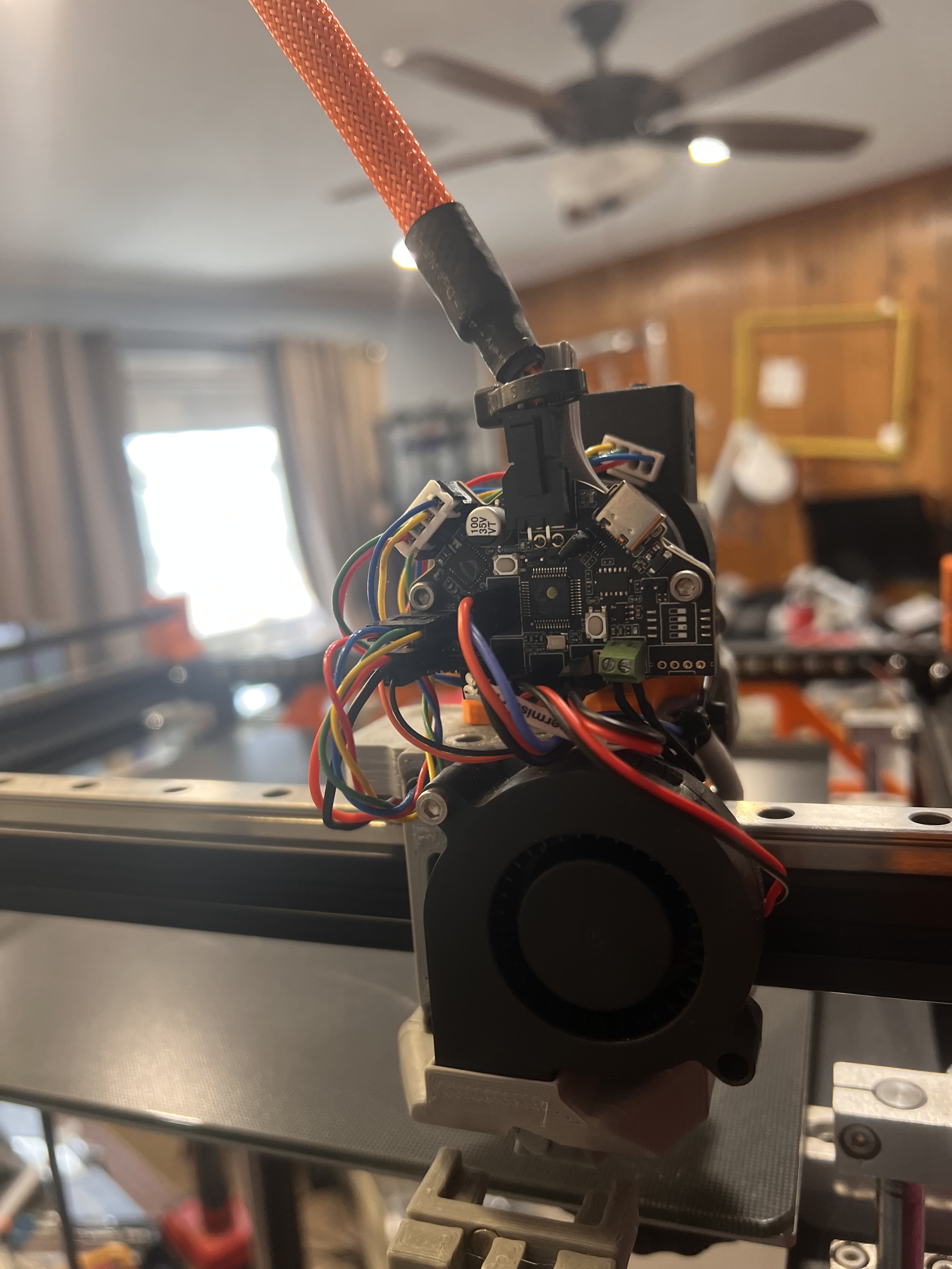
E5+ with the board standing up…
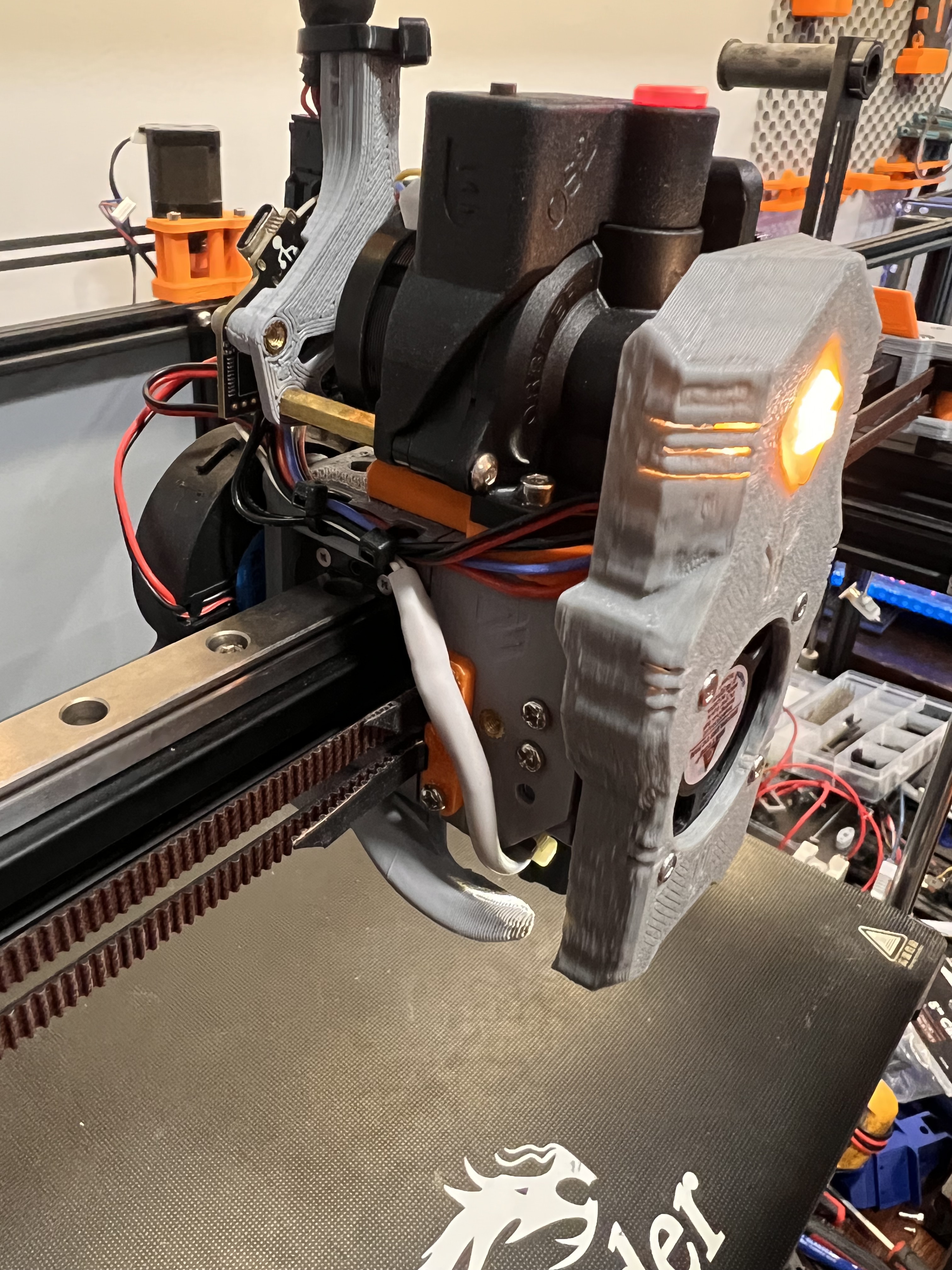
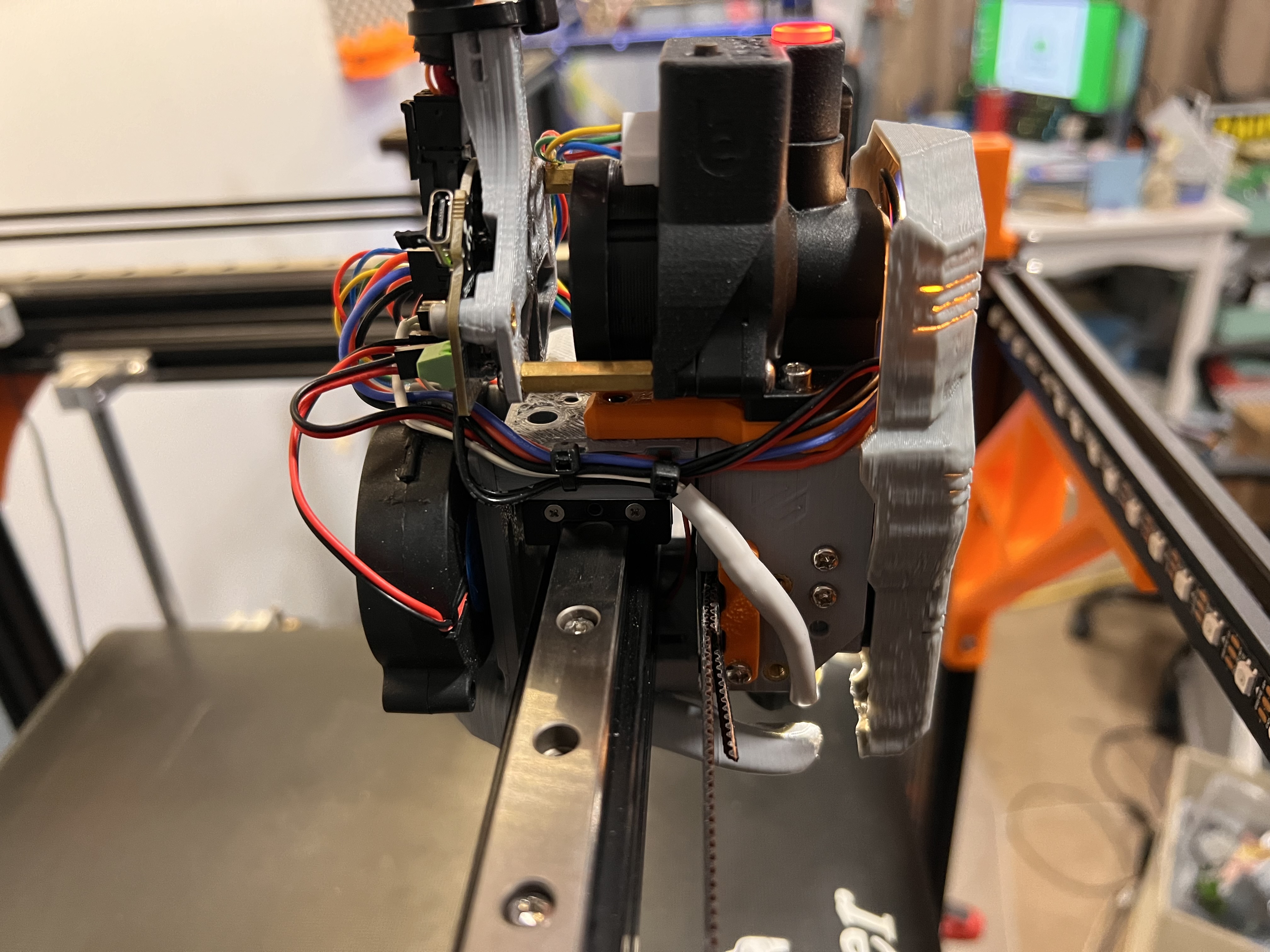
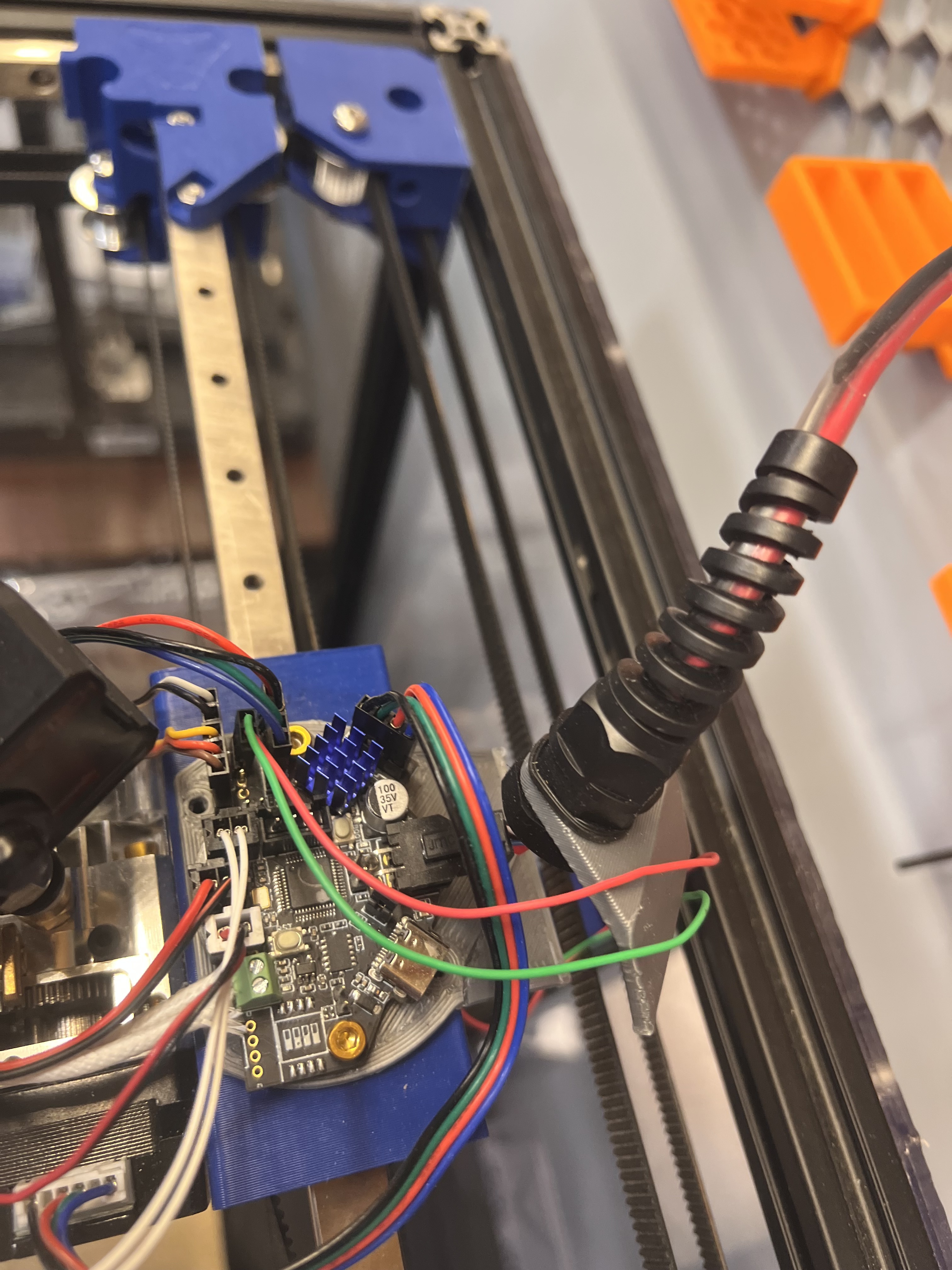
V4 with the board laying flat and my failed attempt at a bracket for it…
1 Like
Oh the CAN bus thing has me way way too interested. It’s a good thing I didn’t tear down my smaller printer. I might have to resurrect it with a manta 8p, cm1 and ebb36.
If we don’t get anywhere with the Jackpot and Klipper this will be on the V5 for sure. Still holding out for the jackpot though just for the coolness factor!
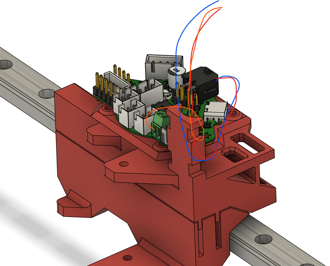
I am not seeing how this is not enough support? From there you can bundle it with your CPAP tube or PTFE, right? The wires are only free for 1-2 inches.
2 Likes
Yeah I am good with it like that. Just will need to remember to leave that distance of cable without the filament in it so its plenty flexible. Thats all I was saying. I see no issues here.
Okay, I thought I was missing something there.
1 Like
Z axis - Linear bearing or V-wheel?
Okay, I still like Linear guides slightly better.
They are easy, cons, they are expensive. ~$22+ on Amazon for 300mm (250mmZ travel), goes up a few dollars per 50mm. Lets just say $70 for the Z rails. Honestly, I just trust them more and have never used V-wheels in any real capacity, and it means a slightly more simple BOM.
V wheels are cheaper, but take more effort to tension well. We can get a few wheels and print the rest for about $25 for the 3 Z rails, or something like this is ~$32 for three Z rails. You also need to be sure to get V-wheel Extrusions (not a big deal). This seems like the best choice as it saves ~$38.
Looking at those v-wheel plates, I kinda don’t see a reason we could not have both. I think if I designed a part for linear rails, it would take three steps in cad to cut it off and add screw holes for the Vwheel plate.
For the rest of the Z, I know you want the steppers off the Z plate mounts, Steppers up top for easier wiring, and want an optional lead screw mount.