Instead of flipping a whole box up like you make, think of it as a top door panel, or even just one that slides into the extrusion slot. A whole flip box is a lot.
I think you mean the X up on the core? That is how we have run them for a few versions now. one less place to run a wire. I am assuming the lower voltage is not a big deal for noise, I have not heard of that being an issue yet at least.
Another way to do it would be to mount it high on the back stepper to hit a flag on the core. That can be done with homing Y before X but it means a substantially larger part.
I’m not super worried about endstop switch electrical noise, I’m worried about mechanical interference with all the stuff that comes with a hotend/extruder - none of which is in at least the CAD you’re showing.
I’m not a fan of setups that require specific homing orders to prevent breaking them. There’s 100% certainty that a dummy like me will eventually and repeatedly home the wrong axis at the wrong time and end up mad and then sad.
But, I may just not be seeing how the switch is in. I’ll keep looking to see if my worries are real- but probably just my not groking how it goes together and how it moves.
The bottom view is just as bad…this thing is so random.
Ohhhhh, yeah it can get tight, but it is not too bad. Once I get the h2 mocked up I will commit to a endstop location.
it gets set in the firmware so you can’t screw it up…but I prefer to home both simultaneously, so that is why it goes on the core (or the truck)
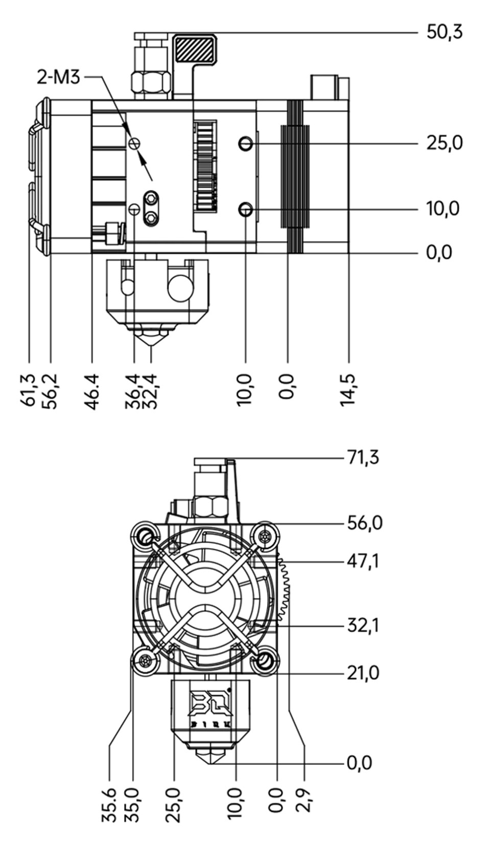
OMG…the drawings for the two are completely different. WTF. The revo is worse, How do you measure from a 0.4mm hole off plane to anything. These have to be the the worst drawings I have seen in a very long time.
I am going to mock up one H2, if you get a different one slight adjustments will need to be made, but not by much.
I just need to get two in there so I can figure out how to make the bed location parametric to a feature that is so far in the future. I have an idea but I need a couple in there first.
Almost forgot still need the belt ptfe spacer holderer
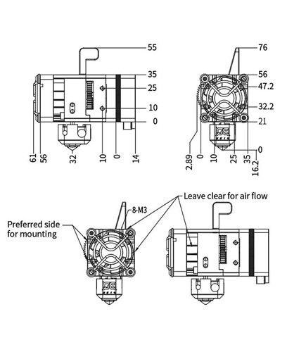
I have the H2V2S and the side with the gear sticking out where it says this is preferred for mounting… isn’t. It works for holding a fan, but the truck mount: on the opposite side. The threads are shallow (I think I used a 6 mm M3 with a printed part to hold the fan on. The 8mm screws bottom out. I’d say they are tapped like 3-4 mm deep… maybe 5 mm. there are 2 holes on the top, on the back, and on the bottom next to the stepper that are preferred for mounting… if that helps. I can get you measurements for offset on any of it if that helps.
Yeah the manual is even worse. I noticed that error. I think they are looking through the back in the drawing and did not realize it.
It is the worst.
Thank you, I have a couple here. I know some of the holes are super deep, some are shallow.
I have already made the mount, with top and bottom screw locations. (flipped the printing orientation) I also made both belt screw holes look symmetric, and smaller.
So that one truck insert piece is ~$23 each printed in stainless or aluminum. MFJ nylon is good to up to 175C and is ~$6 each. Have not checked the core yet.
Man we can make a frigging beast like that a couple MFJ Nylon parts.
Aza, if you are planning on doing a 80C+ enclosed super collider edition, I bet that ~$12 would be worth it.
You can print nylon FDM, the issue is it needs to be printed from a sealed container, it is crazy hygroscopic. Other than that I don’t think it is all that crazy in terms of temp or anything else. It is about the same rigidity as PLA just way higher temp resistance.
PC is the one I would shoot for. Not really sure why everyone goes for ASA, I think PC is the “dream” material. Maybe there is something I am missing.
I chose it because everything I saw it was just like printing pla just hotter. Now a lot of things I’m seeing say ABS+ is real easy to print. Haven’t done any research on PC before but guess I will look into it tonight lol.