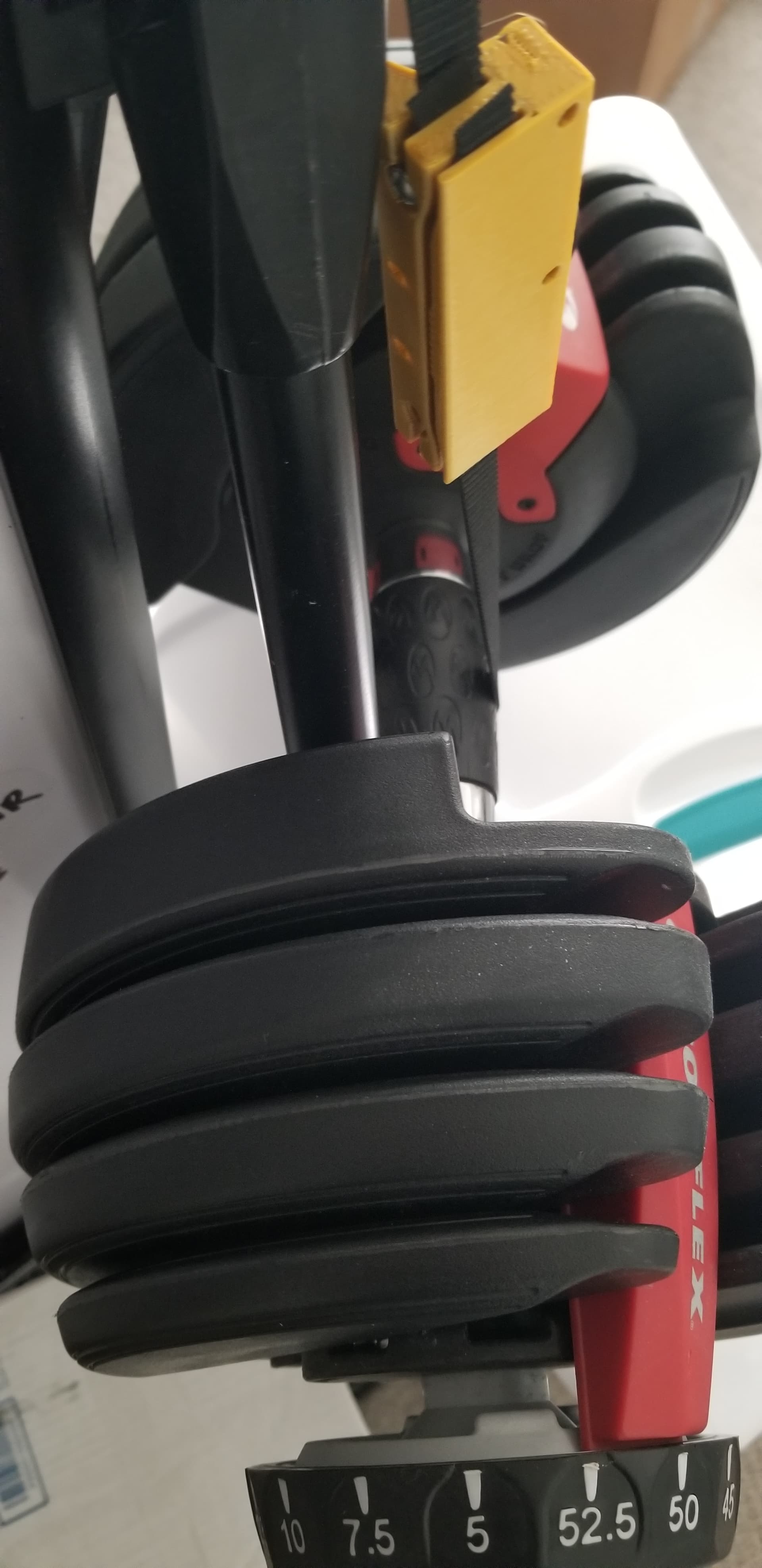
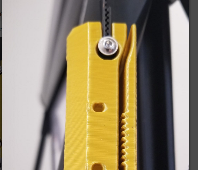
Holes could be smaller/tighter? Looked like this after ~15hrs…
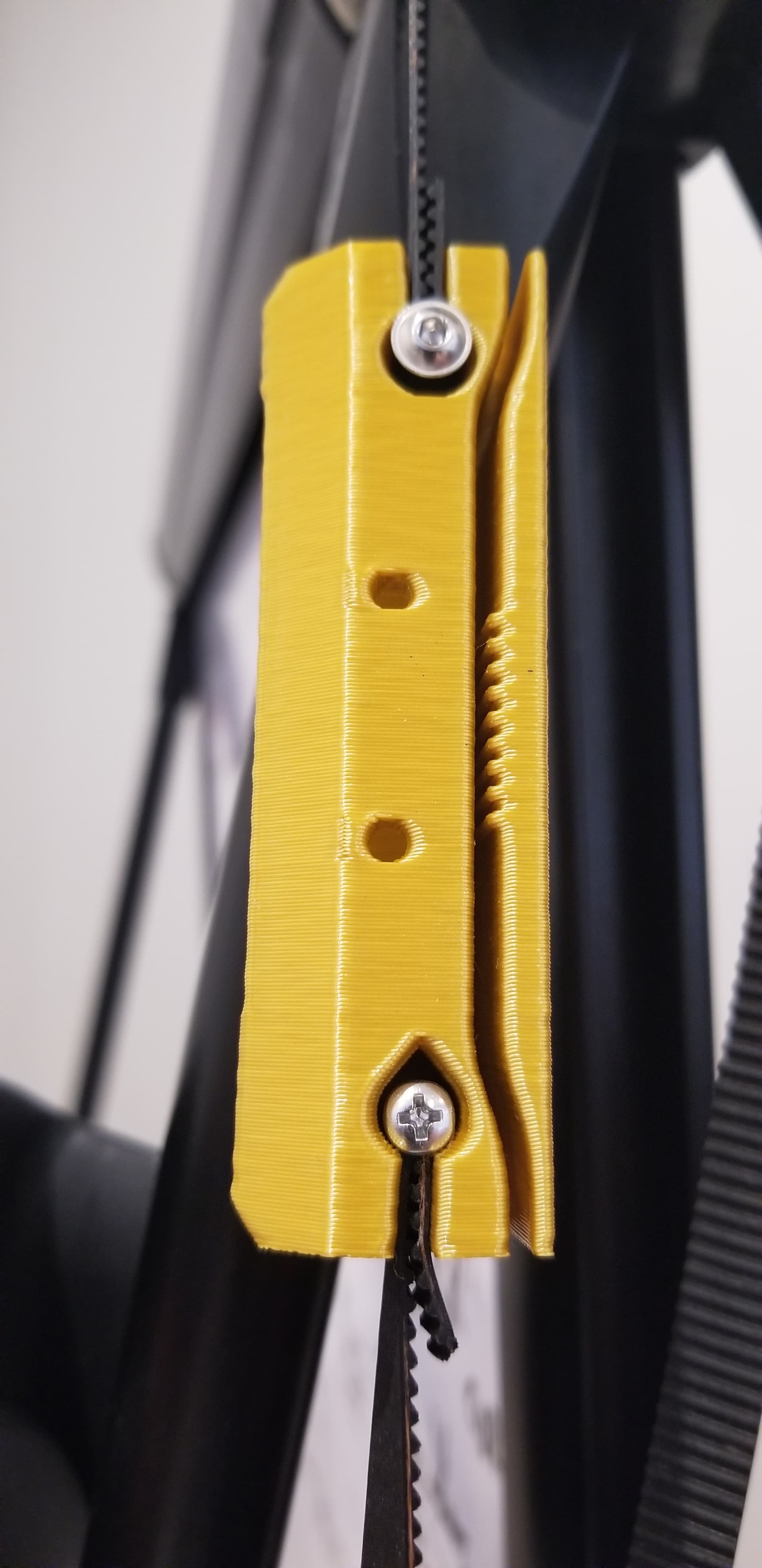
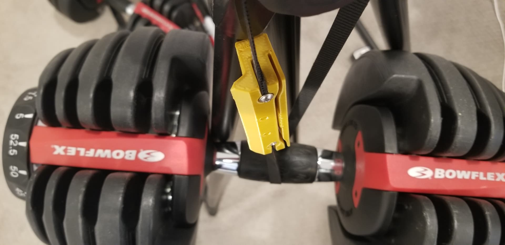
Testing 50lb split between printed teeth and a self grip end…
Holes could be smaller/tighter? Looked like this after ~15hrs…
Testing 50lb split between printed teeth and a self grip end…
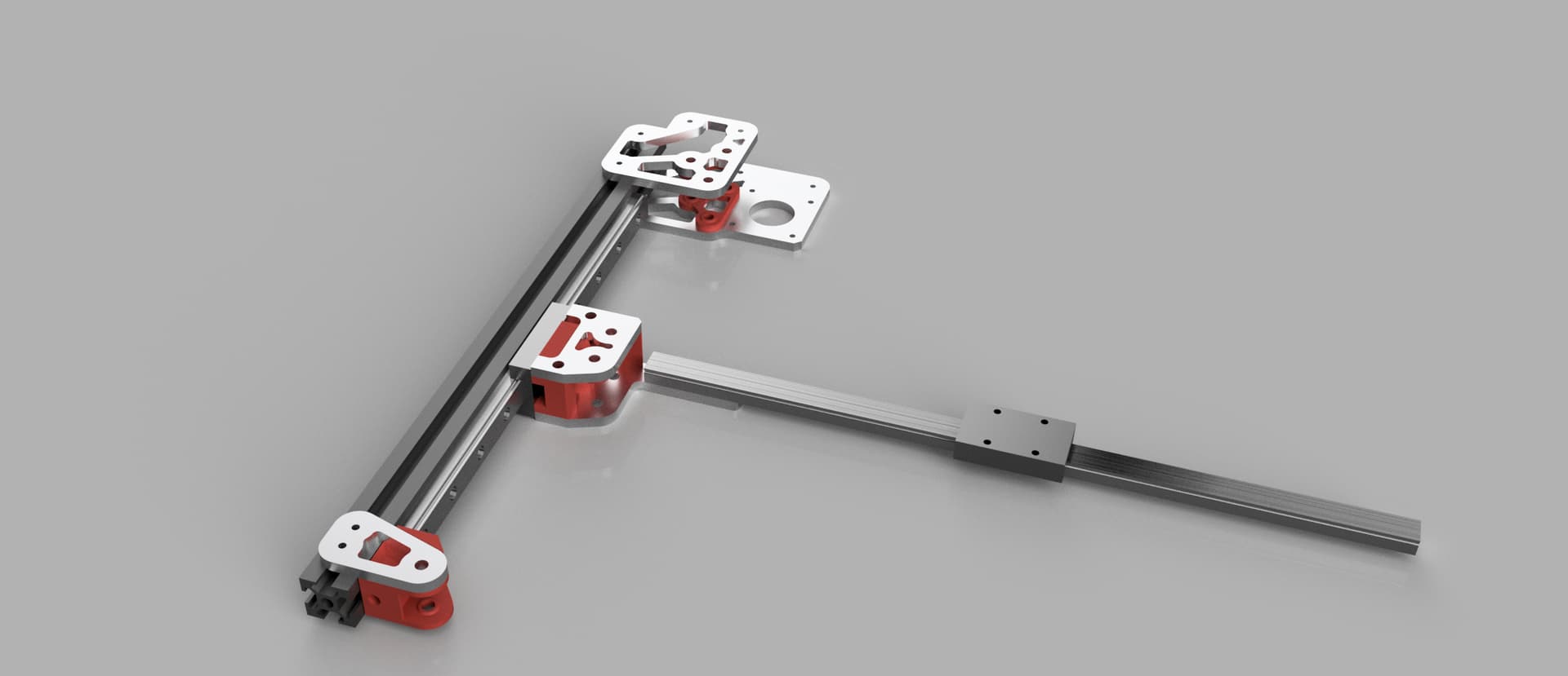
I couldn’t put my finger on it at first, but it’s a Jeep… it reminds me of the Jeep front-end
Remember this will also have a top on it, and be clamped front to back.
I don’t remember what numbers we came up before for the peak belt load.
The screw wrapped holes, yes I can make them smaller or more adjustable. I had not looked at them close, I was far more worried about the teeth.
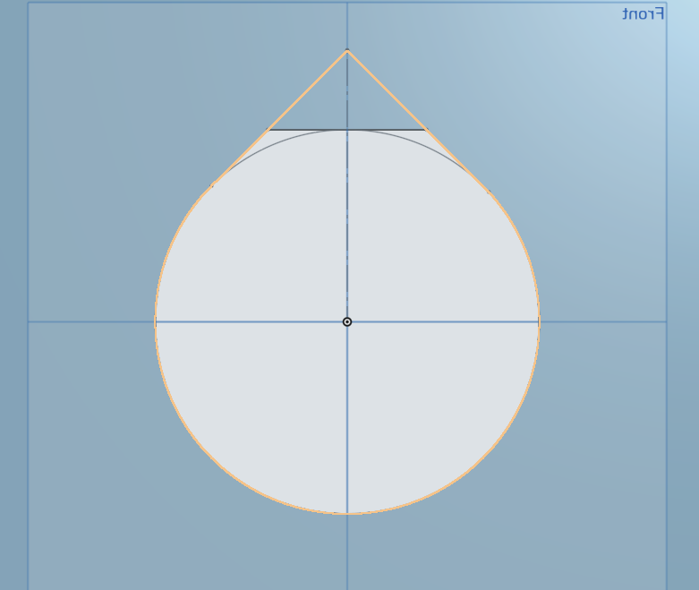
Dunno if this helps but I often add another tangent horizontal line at the top so rather than it going to a full teardrop kinda shape, instead it’s just slightly squared off. That way it gets detected as a bridge by the slicer. If it’s a larger hole, I’ll space the line up a 0.5mm or something if it’s critical to not have anything in the hole, but usually it works out ok.
No idea if that’s a common approach or not.
Absolutely, I can cut it down. I figured it was hidden so not that big of a deal but I can put some lipstick on it.
The normal holes are fine with the bridging they get because you can always jam a screw driver in there , that I did a little extra so the belt would not be an issue cramming in there.
Broke a personal record on Thursday. The bridge on my daily commute was closed because of strong winds. But the walk/bike path was open. The meter said 78mph! (35m/s) Crossing the bridge was surprisingly easy, because the bridge “cuts” the wind like a wing and made handling managble. The flat ground on the other hand, was messier. The wind threw me off the path many times…
I’m sorry. I broke the rules! You shouldn’t mention the weather, I can’t help it… ![]()
Well I would have a hard time leaving the fireplace in those conditions, that is just nuts!!!
And Endstops are tight.
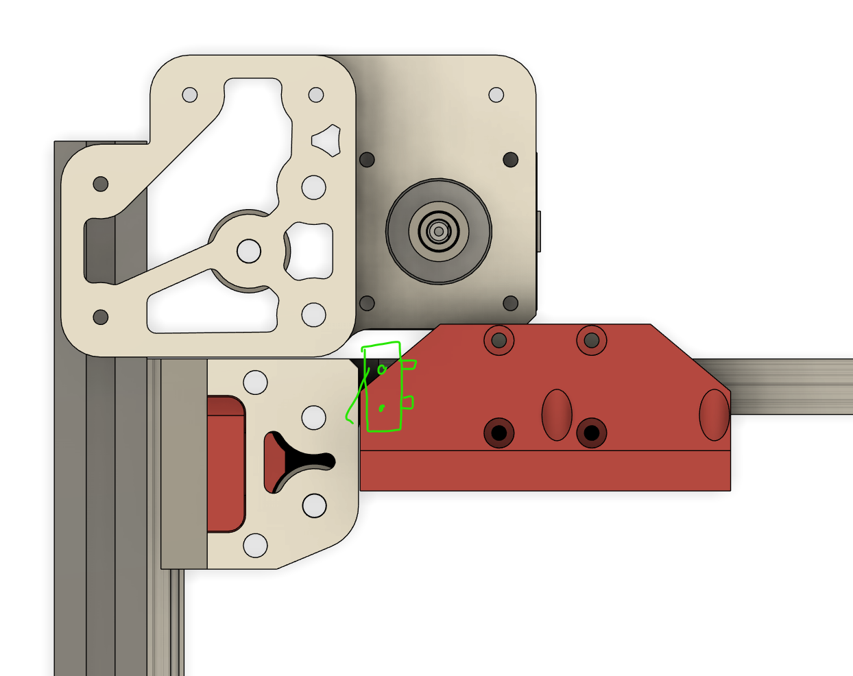
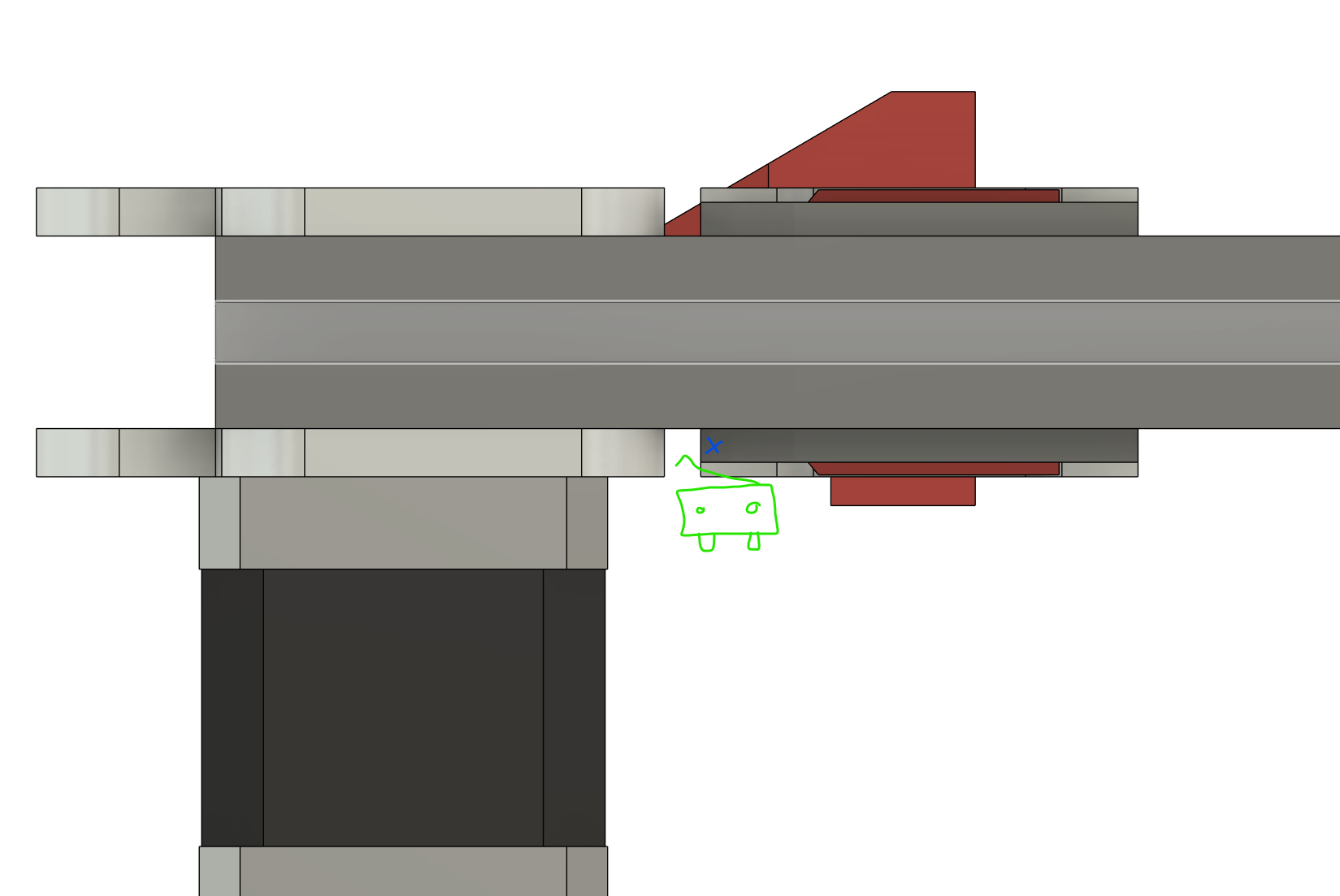
I think if the X endstop goes here, you can add extra room to the far right if you need it for crazy stuff.
And for the Y, If it gets it’s own part here under the rail it can be adjusted forward if you want to add extra room in the back for wires and stuff. Just have to take a look and see how it might trigger on the bearing block
B looks sexy!!!
Honestly they both look good. So if no difference in strength or rigidity I vote B
Yeah, but only because my test rig is twisted and janky. No fault of the part. I expected captured/encased bolt to be fine.
Didn’t expect cool looking tear drop on the small opening. Expecting printer bridging, and forcing bolt in during assembly to be good enough for tight fit?
50lb split between Teeth and self-grip is still holding after several hours (see last pic in this post ).
For the A vs B designs.
Currently mounting cam on front corner area of my v4. Consider 1-2 mount holes on plates for accessorizing, that might be nice to have. Maybe gratuitous future use bolt holes happens later though…
Will lid, filament/runout-sensor/umbilical mounting affect corner plates (above and below XY 2020) ? Maybe aesthetic cutouts are figured out after Lid finalized?
Thoughts on XY Steppers being outside the frame like RailCore, would that help with usable space? Although cool Steppers seems to be nice, even if stepper temp is in 80deg chamber, from previous comments, didn’t sound like that’s a problem providing good high temp rated steppers are being used?
This is cool, like how you’re maximizing use of existing parts reduce overall BOM/parts/time/cost. Looking forward to seeing Z take shape…
The teeth are holding it from coming out, it wedges the screw against the corner edges. If should have zero force in the Z direction. The V4 has non-trapped belts and the opening is facing down, this should be even more secure.
When it stops raining here, I have 50 lbs I can hang on one…I just want to see how long it lasts.
The bottom plate got no reductions, top minimal.
Just because if I get them laser cut it is an extra few pennies and looks interesting. If we cut them ourselves it is very easy to not use lines in a DXF.
Where? Other than the core I don’t see room or a need for extra holes? Would mounting to extrusions not be easier?
That kinda depends. I can make the plates smaller but if people are parametrically making them to use M5 screws they will come nearer to the edge. With the M3’s I can go much smaller, I just need to catch the other side of the slot.
I don’t think a hinged lid will be part of the basic design, I can add a basic enclosed design, with a front door and flat hinged or slide in lid.
I am purposely leaving the actual frame/exterior for last. At that point we can see what needs to be wrapped up.
Usable space? Right now with the folded belts having the stepper in the back is only taking up like 7mm extra, if that. If you move them out back you gain that 7mm but lose another 42 on the footprint. you could decrease the interior volume by x=-7, but in crease the footprint by x=+35mm? If I had to guess.
Yeah, am liking the v5 Core belt holding improvements, even without the top encasing.
Yes, the existing 2 holes in the front Corner plates for bolting to 2020 could work. I need to see whether vibrations when mounting Camera to a corner plate are significant problem. Am using small Pi camera with 70deg FOV, flex cable down the Z extrusion to Pi controller.
![]()
Consider plates having setback of 4mm+ to enable Lid to land on the extrusion. Pic above shows 6.9mm setback, which was too big, since I ended up making Lid from 1/8" instead of 1/4" panels. If I was to do-over, I’d use 1/4" panels for the flip lid. But would design so 1/8" was proud of the extrusion edge, that way I’d end up with the Lid being flush with the 1/8" side panels.
I appreciate Flip Lid isn’t interesting to people building for a compact farm setup with restricted height.
An accessory example (not shown in the above pic)… For v4 am using hole/cutouts at the ends the vertical extrusion to create TPU plug caps that also help guide the Lid square, and provide softer landing when closing.
Thanks for saving/sharing the CAD link in first post. Following along and exploring your design as it evolves has been great.
Going quiet on this topic for a bit, as I try and figure out if there’s thing(s) I can exhibit at Open Sauce… Cheers!
Reducing moving mass gets my vote. Added coolness for appearance is a bonus. I also like being able to see the belt path better.
I like this idea, it is probably the lowest real estate way to use those switches, so there is as little movement area lost vs footprint possible. It might take a little more in the way of adjustment for different hardware, but those switches are pretty standard, so it should only be a little. (I used this switch arrangement for my plotter, but never got pictures.)
Doesn’t that leave the Y switch subject to interference with any number of things on the hotend/extruder setup that might interfere with it? Also, snagging on cables? Maybe I’m not visualizing how this works for Y.
Instead of flipping a whole box up like you make, think of it as a top door panel, or even just one that slides into the extrusion slot. A whole flip box is a lot.
I think you mean the X up on the core? That is how we have run them for a few versions now. one less place to run a wire. I am assuming the lower voltage is not a big deal for noise, I have not heard of that being an issue yet at least.
Another way to do it would be to mount it high on the back stepper to hit a flag on the core. That can be done with homing Y before X but it means a substantially larger part.
I really really like the way this looks. What’s even better is that I think I can make all these pieces pretty easy on my mill.
If you get rid of the fancy stuff they should be fairly simple.
That and you can stack the plates and make multiple at the same time since you need 2/4 of each one.
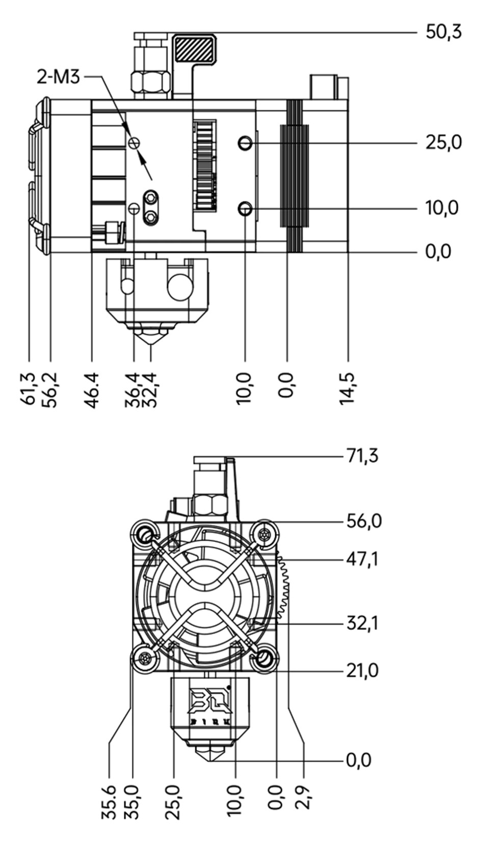
Since the hemera is in there already, I was getting ready to add in some H2 mounting ideas.
Newbie tip…use a feature that can be easily measured as your reference point.
Why the heck are they using the stepper inner endcap-end of the stepper as the reference? No screw mounting depth…Just bonkers.
Weird!
I’m not super worried about endstop switch electrical noise, I’m worried about mechanical interference with all the stuff that comes with a hotend/extruder - none of which is in at least the CAD you’re showing.
I’m not a fan of setups that require specific homing orders to prevent breaking them. There’s 100% certainty that a dummy like me will eventually and repeatedly home the wrong axis at the wrong time and end up mad and then sad.
But, I may just not be seeing how the switch is in. I’ll keep looking to see if my worries are real- but probably just my not groking how it goes together and how it moves.