Help develop the next MP3DP!?!

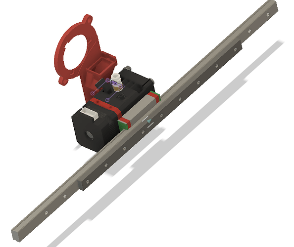
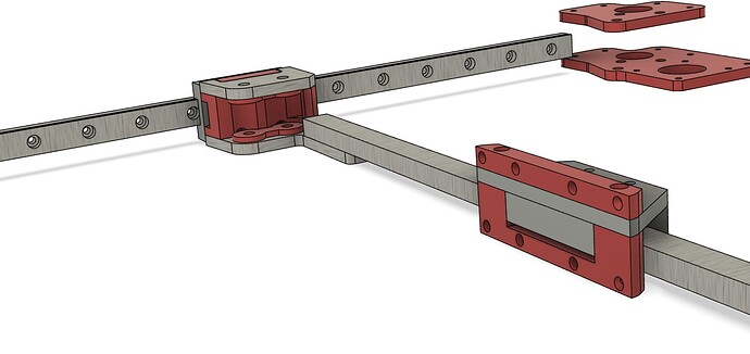
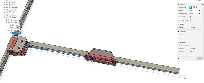
Yes. I think so anyways. That’s the Y rail and truck there and the mount where it would be on the x rail.

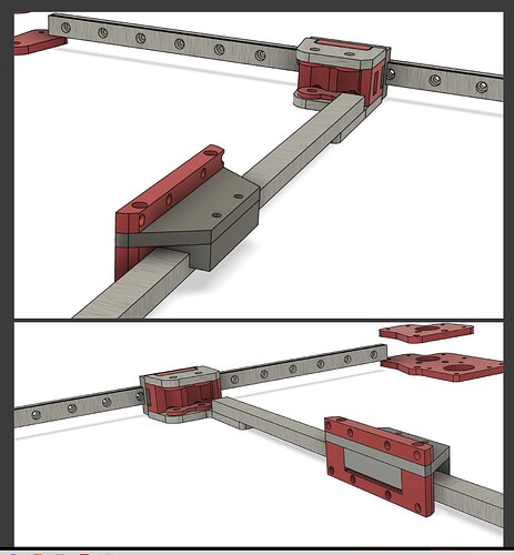
I still say if going flat I would prefer the bearing to be on top. That just makes it where I don’t have to stand on my head to get the screws lined up. And will make it not only rely on the screw heads to hold it to the block but also gravity lol. I’m sure at this light weight that doesn’t matter but it just sounds better in my head lol

Yeah I don’t disagree there. But still a good time to double check square and stuff like that if you haven’t in a while lol. I know I checked mine before cutting the panels for the E5+ and it was still dead on. Always nice to see.

Thank you for taking the time to explain it better. Your timing with this is perfect. Much needed distraction!!

I like the lower mount with the carriage facing up. I expect you could use the rail and a portion of the sandwich on the y rails to give it more strength and rigidity. Using a long screw all the way through the sandwich on the last hole of the rail maybe.

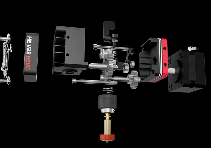
As far as the extruder, I am a fan of the H2 Series. Way more options and way less cost. I am running three of them on my different printers.

of course there is this… Smart Orbiter v3.0 – ORBITER PROJECTS

In that picture it is bearing and screws up. You said it last time and it sounded good to me as well. Why fight gravity.

It is hard to do. When I look at after the fact it I am realizing I visualize a lot of it in my head. I just imagine the parts in place and kinda don;t realize it.

Sorry I will try and put is some rough parts so it is easier to visualize for everyone not in my head. I guess I need to be a bit more of a CAD monkey in a group setting.

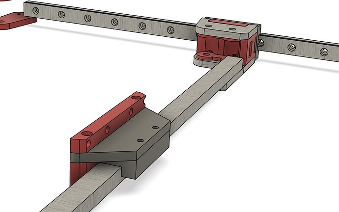
exactly. The truck as shown has some things I like. The plates fight the idlers getting pulled away from each other and at the same time supports the X rail from twisting. The downside to the plate/rail is the nuts we use on the M3 (I think those will be the Tnut from the extrusion with M3x10 into a printed part to stop them from spinning).

1 Like

We have had a few votes for a flat rail, and one for a Vertical. I am going to take the flat a little further and see if any issues pop up.

If you want vertical let me hear your reasons. At this point to me they seem pretty 50/50. The belt routing seems slightly easier flat…I think.

1 Like

It’s not that I “want” it vertical, but if I were designing the printer, it’s likely what I would do.

Most of that is rooted in “feels” more than anything else, and maybe just because it’s what it feels like I see more often.

It feels like vertical would be the stronger orientation. Probably because it just feels wrong to me have the flat or skinnier side facing up when building things across a span. So it just “feels” wrong to me, but only because it’s something engrained in me from all other things I’ve built where it matters.

I don’t really know, though, how much deflection a 400mm rail has with just a 1-2lb toolhead riding on it.

Turning it vertical though could also cause some vibrations, I guess, in the Y direction at the center of the rail at high speeds, which is why I assume most of the ones I’ve seen have some extrusion reinforcement.
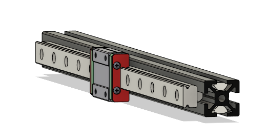
image

Which I guess I see as another benefit, if you’d like to reinforce that span, that orientation feels like it would be easier way to be able to attach some extrusion.

Having the extrusion there also gives a landing spot for cable chain if you’re not doing CAN and looking for a wiring path.

The vertical orientation with the plate mount on the front also feels like it would be easier to make a custom mount/adapter for anyone using a toolhead that is not part of the official offering.

It also feels like vertical orientation also makes it easier for anyone, if 2020 extrusion exists there, to potentially forego the linear rails if they can’t source them for a reasonable price and use POM wheels and a carriage there if they wanted instead.

So, my original “vote” was more so just saying “I like that” because your picture at that time had it oriented in the vertical direction, which happened to align with my preference

But there’s no real reason other than the feels. The only 3D printer I’ve ever used has a 300mm piece of extrusion with a POM wheel carriage in X, so I can’t really say for sure how much any of that matters with the rails.

1 Like

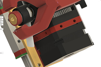
Quick rough sketch of what @niget2002’s Aluma Core experiments got me thinking about some ideas for my BIQU H2 setup…

“Core Plate” would actually end up being taller/wider with mounting holes for peripherals (EBB36) and/or 3D printed mounting parts (e.g. maybe stub for X end stop). BL Touch can mount to front holes.
That red band on the H2 has 2 holes on each side including top and bottom.

Personally have the same feels, all my joists and rafters are vertical. I don’t have any formal mech training.

Currently rough sketching what to do if holes are not accessible using single plate… Can maybe solve with another plate…

Edit: work in progress… still sketching…

Moved content to new post after Ryan’s comments below… This topic’s going too fast for me to give my armchair CAD feedback, and rough sketch…

My thinking here, at least for doing it differently last time (V4). In the direction of gravity we are only supporting the beam weight and extruder weight. In the XY direction, we are supporting that while accelerating it at 10,000mm/s/s. I see that as the direction that needs the most support.

I also know there is probably very little difference in terms of beam deflection for a MGN12 with these loads. So I am indifferent in this regard. If we went to an MGN9…I might fight harder for it.

The bearing block is also equally rated in both directions (from what I remember).

Adding a beam is possible in either direction, you just have to choose where you want to add the space it will eat. In the image you show it will make a deeper printer, flat will make a taller printer.

I will say I think a hollow aluminum extrusion as a support for a hardened steel rail seems not needed.

Using it as a attachment point is understandable.

Yeah. I agree. It might be easier if you bolt all the way through the plate and adapter. I will counter with I think that will always lead to an extruder further away from the bearing block. Mostly becuase with a flat plate you can touch the bearing block and if anything hangs behind it can, where with a vertical plate everything has to be in front of it (for the most part).
I do think vertical might be easier … One of the things I really want to see is what the mounting stuff looks like with a little more refinement mostly in terms of where the belts are.

On the vertical plate of 78mm wide the belts will still need to pass behind so that will add ~8mm or more to each side. Flat I think they easily pass behind so we get a more narrow core.

I agree it seems more proper to me as well, this sandwich mount is more complicated with the accounting for plate thickness but it is really intriguing me.

They don’t move, they are fighting gravity. We are fighting acceleration many times Highler than gravity.

So this is what I was trying to explain earlier. With the flat horizontal plate we do not have to offset by screw head distances. In that mount you will always have to be at least one plate thickness and a screw head away from the bearing block. Turn that 90 degrees and you can have the stepper touching the bearing block.

I am very happy with the critical thinking.

Try it turned 90 and instead of stacking everything higher bend it over the top of the rail.

1 Like

think about trying to keep all the mass as close to the very center of the rail as possible (Most importantly is where any wires attach as they add a lot of force near the extremes).

1 Like

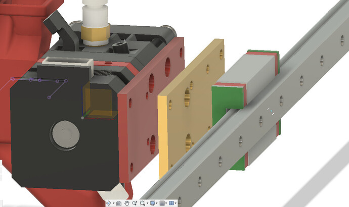
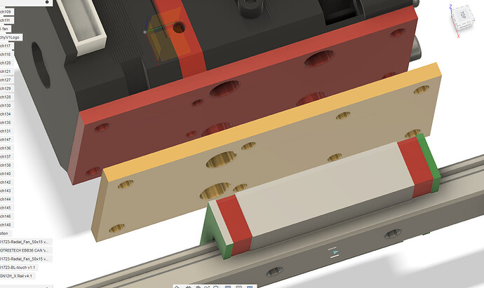
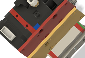
Thoughts on a two plate Core for extruders with inconsiderate hole spacing…

  • Assembly sequence…
    • Assemble Red plate to extruder using M3
    • Assemble Gold plate to rail block using M3
    • Marry Red and Gold plates using M4/M5, maybe slop on thin layer of Green Glue vibration dampening compound between the plates.

In this sketch the Red plate’s 4 corner holes would need to be tapped, since the extruder body doesn’t leave space for nuts. However… The final plates would be taller than this so EBB36 could be mounted, so in that case simpler M5 through bolt with nylock nut could be used for the top. Maybe the plate bottoms could extended down past the extruder to allow nylock nut to sneak in and hold the plates. Do this and the pair of 3mm plates becomes simple to CNC?

Are nylock nuts better/worse than threadlocker tapped holes and metal nuts?


The larger holes provide space for the ‘other plates’ button head bolts to recess. Goal was to allow simple plate fab for bolt holes, avoid needing to do chamfers.

Edit: Oh yeah, belts need to be attached… Um, maybe they can opportunistically be fastened between the plates, and/or additional small belt gripping plates would be attached…

1 Like

I like the vertical. At least the top of the rail will be easy to oil.

I also like screwing the trucks on vertically. But it isn’t a strong preference.

I thought the drawing was for the extruder part at first. And I was really liking the idea of mounting the extruder at 90 degrees. Not for performance, just because it seemed easier to design a mount for everything. I’m pretty sure it would be better for rigidity to have it flat to the truck though.

2 Likes

If I were to design this, I would have the bearing block face the back of the machine. The extruder would be on the front opposite the bearing block.

A U shaped core would be designed that went from the bearing block, up over the top of the rail to a flat plate for the extruder to mount to.

I would mount the extruder to the core, then slide the core over the rail and bolt it to the bearing block. This would put the extruder closer to the center of the rail and reduce twist on the rail.

I might even consider making the U large enough to mount the extruder using the mount holes on the front instead of the back. This would allow the extruder to be slid up into the U and be removed or installed without touching any other bolts or belts.

I really dislike digging around the back of the core trying to bolt the extruder on.

Additionally, this would give a place on the bearing side to mount the cooling fan to also help offset the weight of the extruder.

If you went with the big U design, then the belts could be mounted to something hanging down on the bearing side. Like an upside down U with a lip on the back for the belts.

I don’t know if the Biq extruder has mount holes on the front.

1 Like

Yep, 2x M3s on each front/top/rear/bottom faces…

Dislike this too, after initial assembly though, I’ve spent more time messing around from the front, needing to open the H2 to unclog filament, that was until I figured out better settings.

If rail block, and extruder were on the rear, then, that’d make some other options easier…

The biggest downside to this is if a “support” extrusion is added, then the center of mass is really far away. Other than that I actually did look it it that way.

I feel like the most recent Horizontal plate screen shots I put up is the happy medium to this?

This expands the footprint. We are right up against the belts, so I suggest keeping things on 3 sides not four. So front, top and bottom.

I would need to see a sketch.

You definitely want the extruder up front though right? Clogs and cleaning I want to be abel to get to the extruder. After it is bolted on I only check it once a year or so.
The other options are mounting front the top or bottom.
I know I have seen printers that are sideways to conventional (railcore maybe) The just kinda means everything is on the side.

fwiw, some inside the box thinking… e.g. either mod (drill holes using a nice CNC…) or replace (milled or high temp printed part) part of the extruder housing with holes correctly spaced so no plate needed. Enable mounting extruder directly to rail block.

The modded/new Extruder housing becomes the Core… With belt mounts design in there too somehow…

If vertical X rail, and If going fast enough to be concerned about XY accelerations, then could optionally bolt (and/or use adhesive or spot weld?) shorter (cheaper) linear rail to strengthen middle ~2/3 of the main X rail? Maybe the spare rail block can be used for something. Ideally there’s no additional plates.

I really do not understand how some of the speed runners have not tried this. Make the core the hotend/heatsink and go. they are willing to make some crazy other parts but never just integrated the big aluminum heatsink into the big aluminum core.


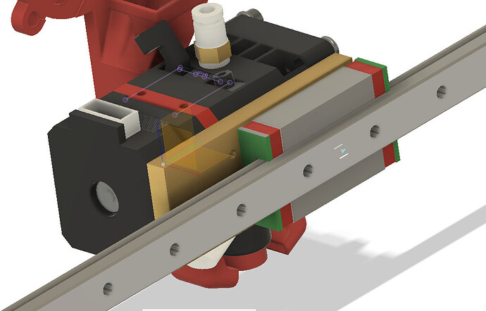
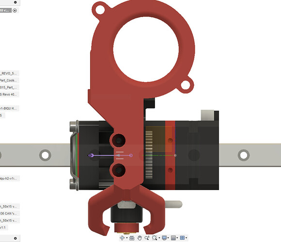
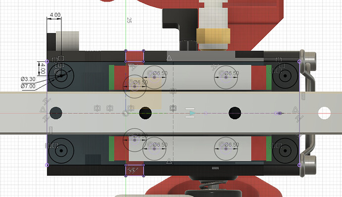
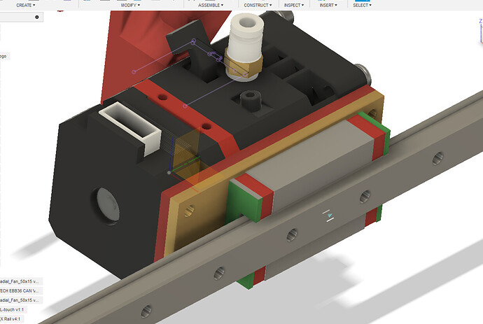
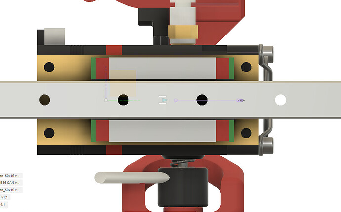
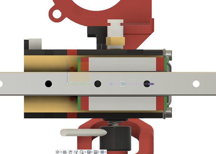
This is just trying to show a very minimal sandwich. As in how different it is to the V4. Seems rigid. Seems easy to move things up or down. Lots of room above and below.

The belts are a few mm out front so it is probably best to add a few mm, but I want to see how minimal I can get the belts as is.

belts in purple.

And now I see the belts with nowhere to go…


With the close belt this close it would need to turn away from the plate.
This config need to have an offset from the bearing, I got the belts too close. All the statements before that I said you can touch the bearing are only true from small extruders, not true for a hemera.

2 Likes

So a vertical rail also has to have that belt offset and that accounts for the bearing block screw heads.

Back to same same. Vertical or Horizontal.

Look how small that truck it though.

1 Like

I really like the look of this! Would be super simple to mount any combo unit to that front plate. Also would be super simple to extend that front plate out a little bit to mount an extruder on the top and hot end on the bottom as well! This seems to really give a ton of options with the bearing on top.