You did but I posted the wrong question.
Looking at the sizes I just posted A regular hemera is 78mm wide. I am assuming anything will fit in that envelope. Do you think that is a good maximum width?
You did but I posted the wrong question.
Looking at the sizes I just posted A regular hemera is 78mm wide. I am assuming anything will fit in that envelope. Do you think that is a good maximum width?
yep.
We will save extruder discussion for next to last as that is not going to be an easy topic.
But please if you want to discuss that later have a couple picks ready to talk about.
This is the part where things are going to start stacking up so I am trying very hard to break this down to one choice at a time. We can revisit things later as this progresses if things start to get in a conflict or a better way pops up.
Feel free to nuke replies if they’re distracting.
Yes. Seems fair that anyone wanting to do something special should have to do some special planning for it. Seems fair that you design for Hemera since that’s something you trust and use most?
Haven’t checked, but guessing that max is wider than typical voron hotend width.
Not at all just trying to break this down to what is really important. While I sit in CAD I have several dimensions in mind…and really I need to focus on one oat a time. Not figure it all out simultaneously.
Well I was voting to go smaller as default but seeing as it only adds 4mm on each side, I think it is a fair target, and that will give any other side fans on other extruders more room to breathe.
78mm looks good to me
Personally, I’m likely to stick with a Hemera now that I have 2 up and running, with some spare parts around for them. As such, that would be good to support for me.
I’m not averse to the H2, the price point is good, I could see myself switching if the opportunity arises, but so far, I’m happy with the Hemera when Im not using that stupid filament that always jams…
X rail orientation.
Which way should the X rail go? Just so we have rough numbers a MGN12 is 27mm wide (across the bearing face) or 13mm thick (mounting surface to bearing surface)?
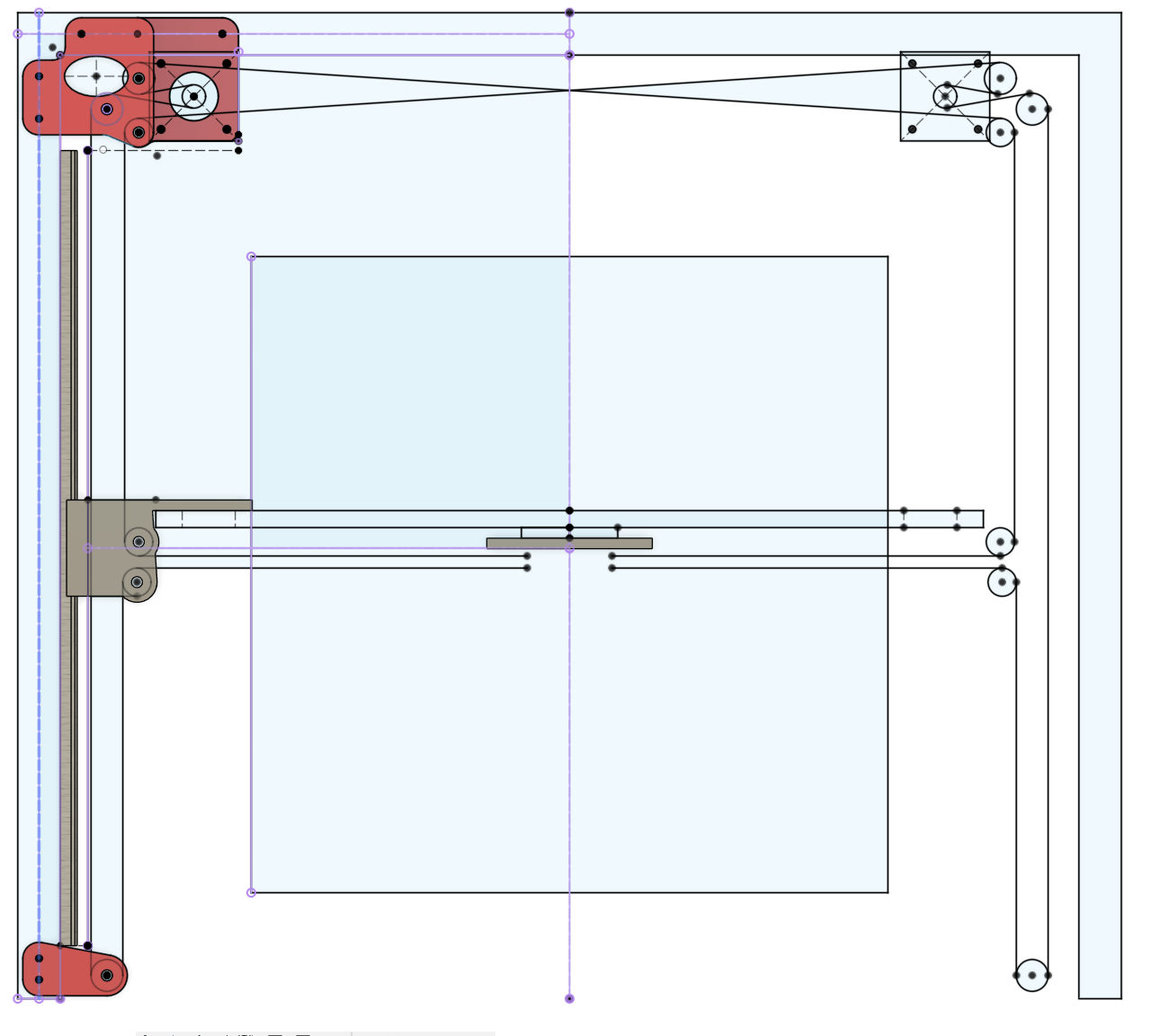
I have been roughing in a couple of things that are not set in stone.
The belts can move, so don’t pay too much attention to them, the gap between the across the front is mostly fixed though.
Facing the way it is shown, you need to also offset for screw head thickness from plate to bearing.
Facing the other way you need to make an extruder holder that comes around the rail.
Laying the rail flat (the V4 way) you need to make a 90 degree corner. Horizontal (bearing face) to vertical (extruder orientation). It does not cost much in terms of space so if any so other than that what are your thoughts? To me either way is fine, I like the idea of a single flat plate for the main core, but we have a lot of options at this point.
I like the idea of having it turned 90º from V4 like you have there
I have really been trying to make a good plate based system for the trucks, hoping it would shed some light on the core design. Nothing spectacular yet, but there are options.
The way you have it should be ok. If you were going to move it flat like the V4 I would invert it with the bearing block on top. But I don’t see an issue with it on the face
It seems to me that flat (like the v4) would distribute load on the bearings more evenly, but as soon as you put torque on it, that likely goes away. The flat plate core seems simpler (and more amenable to a milled aluminum solution) so it has appeal. I also like the rail oriented that way.
That leaves the only real worry being dust accumulating in the bearing track, but that’s a problem the Y axis will have, too, and hasn’t actually been a problem.
I keep going back and forth, flat vertical, flat horizontal, Both would still need some sort of printed adapter/carrier. They seem pretty equal. I think I need to copy the CAD and take both a step further to see which works a bit better with belts?
In my mind, using this flat plate version is worth pursuing because either way it is very adaptable. Provided the belts work the way I expect. Even if someone needed a new flat plate and printed adapted, it would be easy to CAD and print (or cut). The flat vertical looks easier until you start considering screw positions.
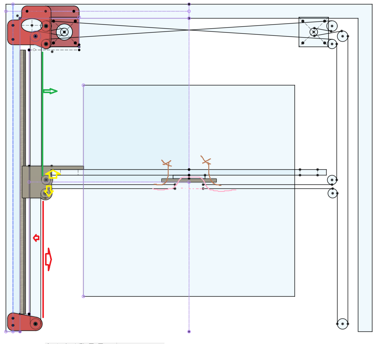
I guess maybe at this point you all might need more info.
-The green segment can move further toward the middle, the only reason I see to do this is to actually stack the belts on top of each other across the gantry, This might cost a little extra width depending on where the idlers end up.
-The red segment can only move if an extra idler is added. If it is we can make it ~8mm more narrow, unless we make the truck wider in that case we can nearly stack the belts. (it might not cost any extra room because I think we have a spare 25mm). This will also let us stack the belts across the gantry.
-The yellow idler positions are free to move it the truck block, and I do believe there is room to spare outside this minimal block that is shown.
-Since the belts are on the same plane we can have one continuous belt so it just needs to be anchored in the core somewhere, pink
-Brown would be how we capture the ends. I say capture because setting tension there requires two large parts and two large screws. I think it would be best to move the tension adjustment to the front idlers to keep the core as light as possible.
Here is the CAD, Very rough not all is parametric yet, just trying to get things situated before making the changes needed.
Of course you post this when I’m not home to look at it lol
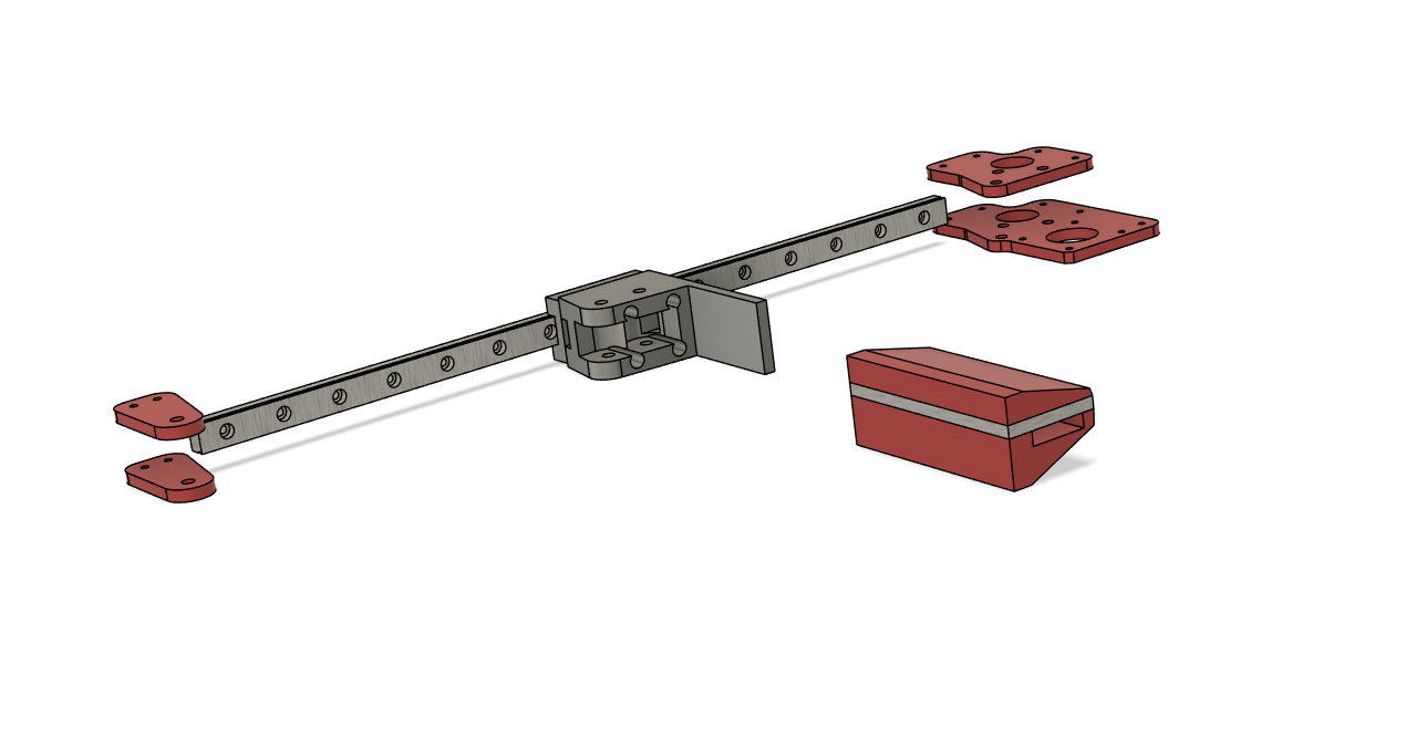
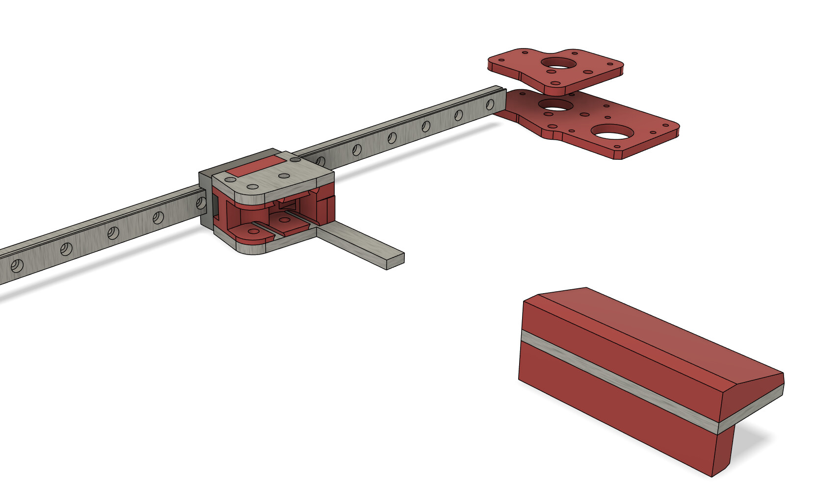
Okay, check this out.
This seems pretty legit right??
In this case a hemera sits in the front, but think of all the room for built-in ducting and wires. You can easily go left right, up and down.
The belts get routed in the printed part.
You can mount touching the bearing block(currently it is showing 10mm in front I realize that is a mistake now) for minimal torque, you can add things behind, on top or bottom.
This entire thing can be printed…but it can also be a plate with printed parts on top and/or bottom. The downside to this combination is you need to account for your plate thickness (currently already in the CAD).
As I see it, if this is fully printed it is just mounted with 4 screws to the bearing block. If this is a plate and printed it is 4 screws to the mounting block and 3 long screw making the sandwhich. In both cases, the parts screw to the printed parts.
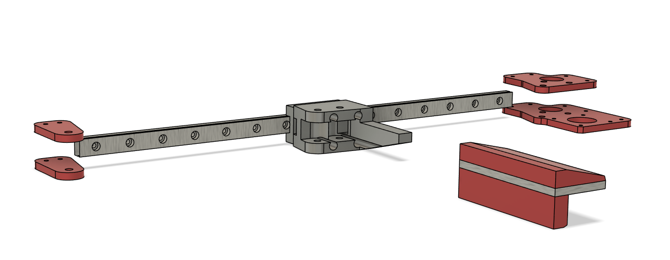
I think it would be more like this (if the bearing is facing up).
I just can not come up with a way to get a plate into the Truck…Or make it a solid milled part. Hmmm maybe I can make it a sandwich as well.
Help me out here. I’m viewing this from my phone so I just want to make sure I’m seeing it correctly
The linear rail is the x rail correct? And the mount you have turned 90°? I can wait till I get home and hopefully see it better.
As far as the sandwich parts I think that is a great idea. Flat plate is much easier/cheaper to source than a larger thick part and also much easier to mill. Nothing wrong at all with mixing milled and printed parts. Just need to make sure your cnc and printer are really dialed in before hand. I really like where this is headed.
So depending on if a flat rail gets mounted up or down facing, the plate goes on the top or bottom. The downside here is not being able to get at the Y bearing block screws, they are hidden behind the plate.
Saved the CAD like this so you can look at it.
So back to horizontal or vertical?
If you didn’t notice before I left room for a plate on the vertical one as well, if you like that way better.