Would some of you who have good cable management care to show pics or advise. I am ready to be serious about my cables.
Thanks
Would some of you who have good cable management care to show pics or advise. I am ready to be serious about my cables.
Thanks
You can see my cable management here:
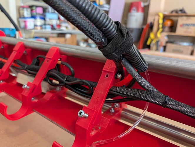
X/Y got the tape measure trick, the gantry got a drag chain with a L-profile. Works well. ![]()
+1 on the tape measure trick. ![]()
I used a combination of heat shrink, mesh loom and corrugated split loom for cable management.
The pictures are for an LR3, but are pretty much applicable for an LR4.

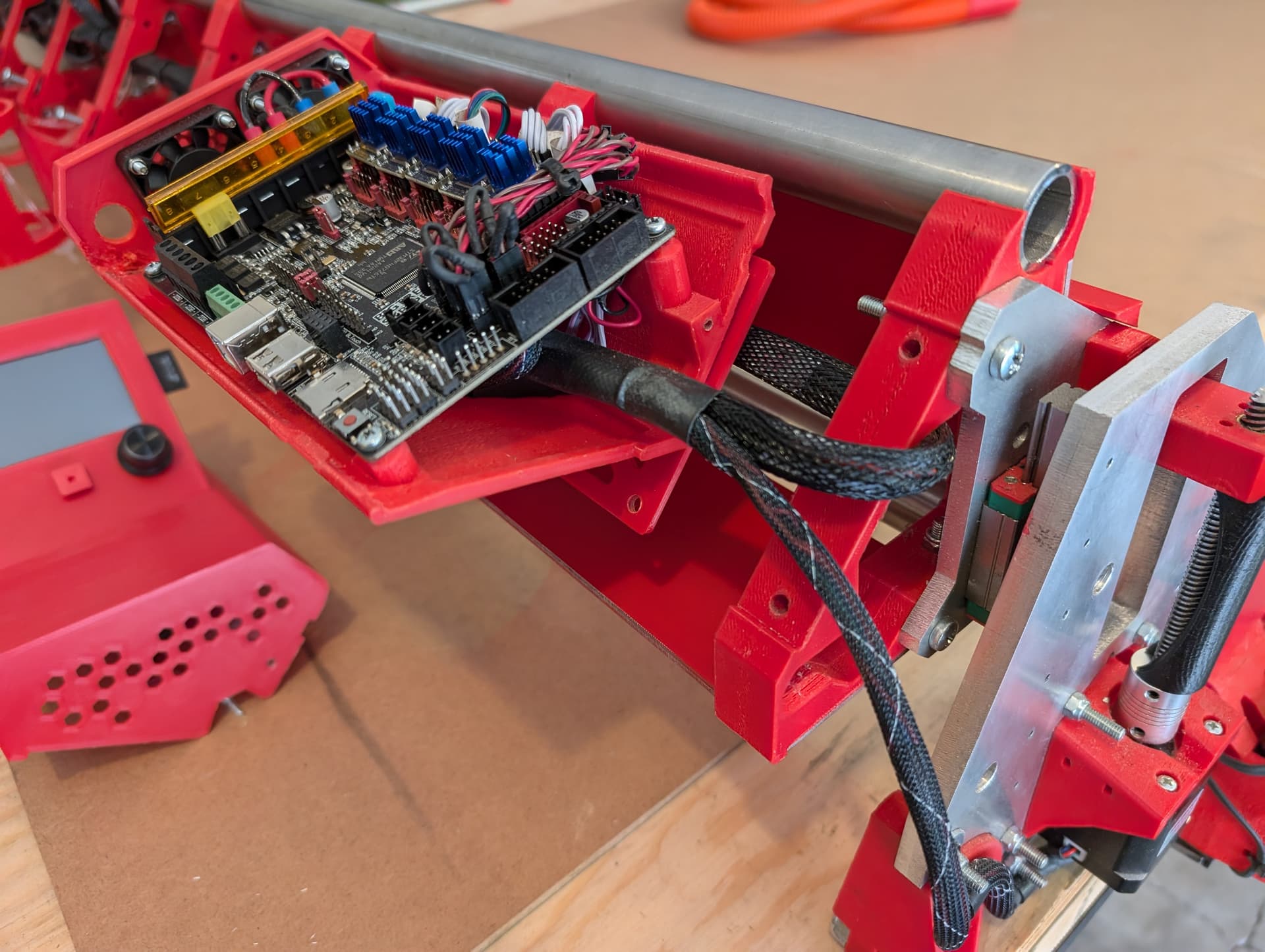
Build thread is here…
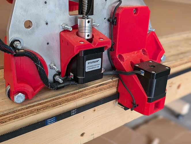
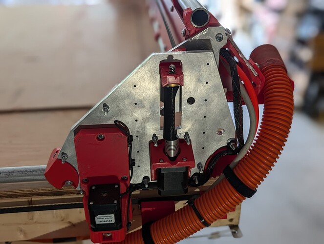
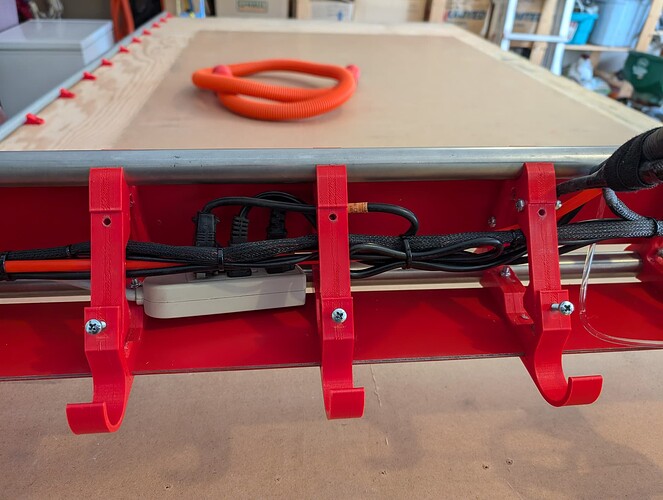
after looking at the big red lowrider, I have changed my mind and instead of offering wiring advice, I’m taking notes. Very nice! Built to last.
For those of us with less confidence in our wiring skills to not bolt it all down and heatshrink it together all permanent just yet, I might suggest some wire trays or cable chains. I’ve seen some helicopters use string for their wiring so it can be easily redone, so that might be an option.
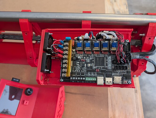
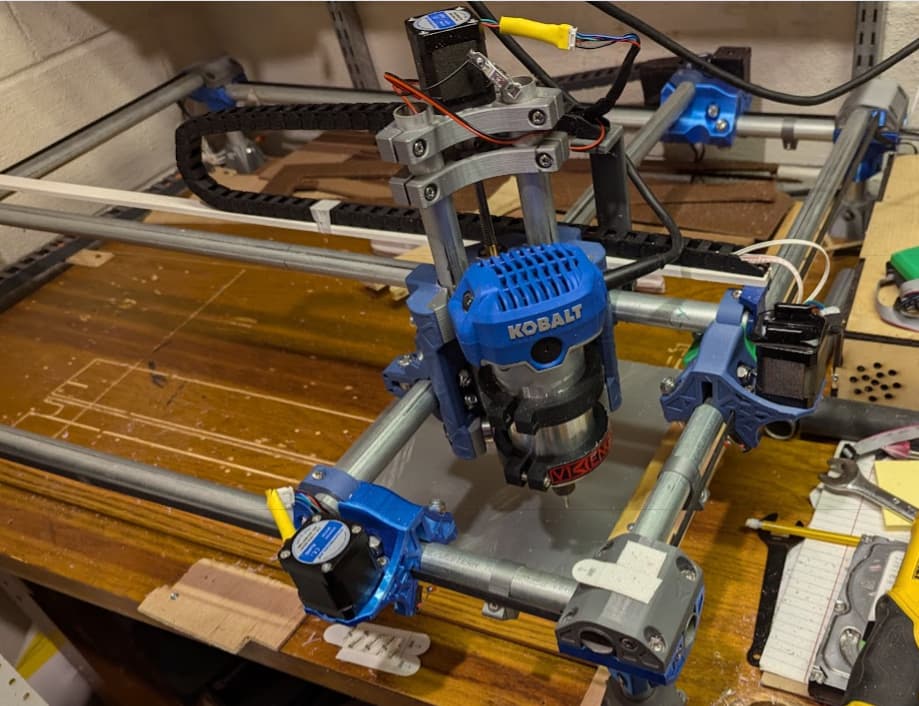
@bmacoubrie Noticing that you asked specifically about the mpcnc, when I had mine, I ran the wires from the controller under the table or through the stationary tube to the far side of the table so loading and unloading didn’t involve wire gymnastics. The far side of the table had cable chains for the x and the y and then the x tube had an extra cable on it for the gantry z motor and touch pad and can be seen in the photo below. While this certainly isn’t the ideal for wiring, it is an example of where you might consider placing your cable chains should you choose to go that route.
Forgive the rough wiring, the intent is to give an idea of placement to get wires to everything. I’m taking notes on the big red build for how to get the wires in a more permanent state and looking and functioning correctly. I soldered and crimped connections to each motor at the motor after I had problems with one of the motors (this was unnecessary).
Closing older topics, to fight spambots