I am not sure what I am doing here.
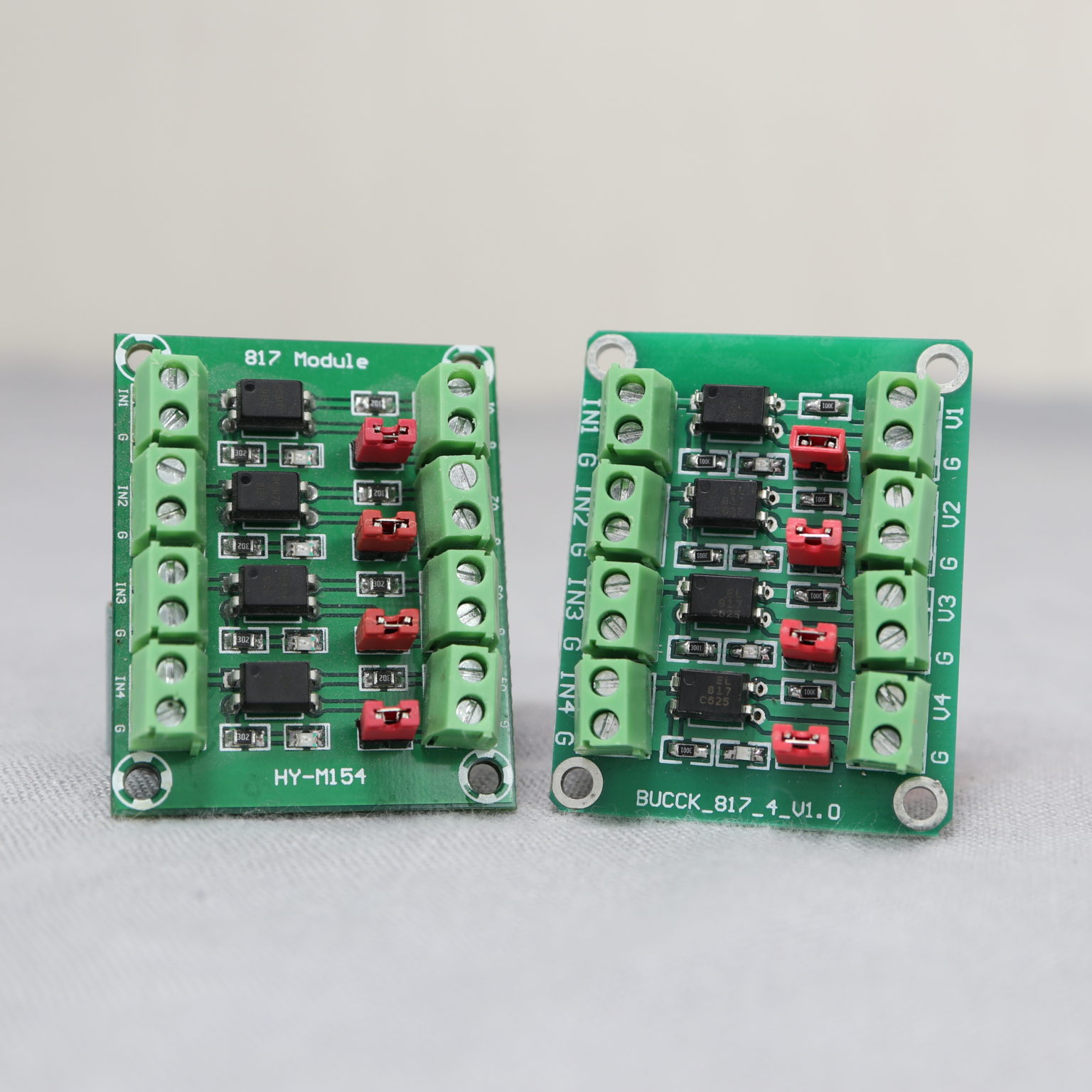
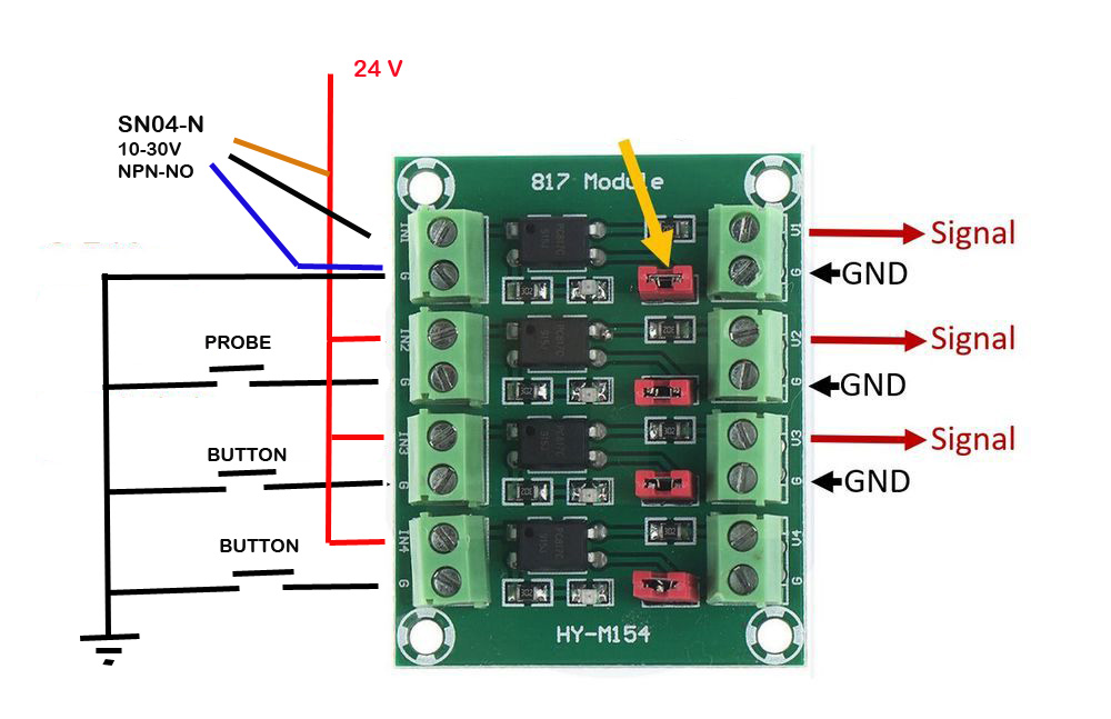
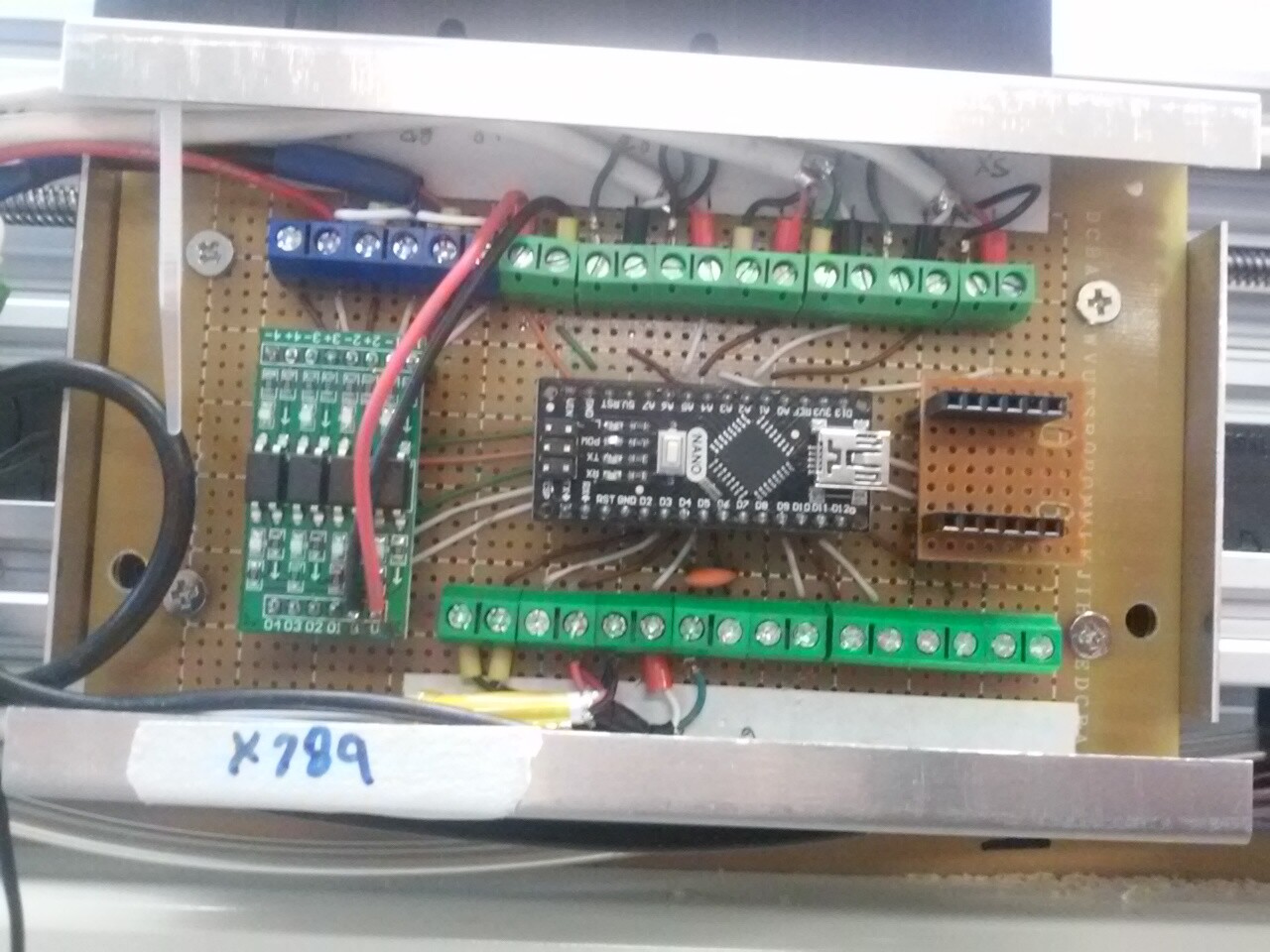
I have two 817 modules that I am using on a Nano for four inputs (button switches to ground) and limits (NPN opto) and probe (switch to ground via an sharp tool)
I can get all to work individually, the output side connecting to the Nano is all okay, but the input side of the 817 modules I am having the problem. Maybe I have to add some resistors in the supply line between the channels?
I am using 24 volts on the input side of the 817s, 5 volts from the Nano board for the output side and I have 10K pullup resistors to stop the channels floating.
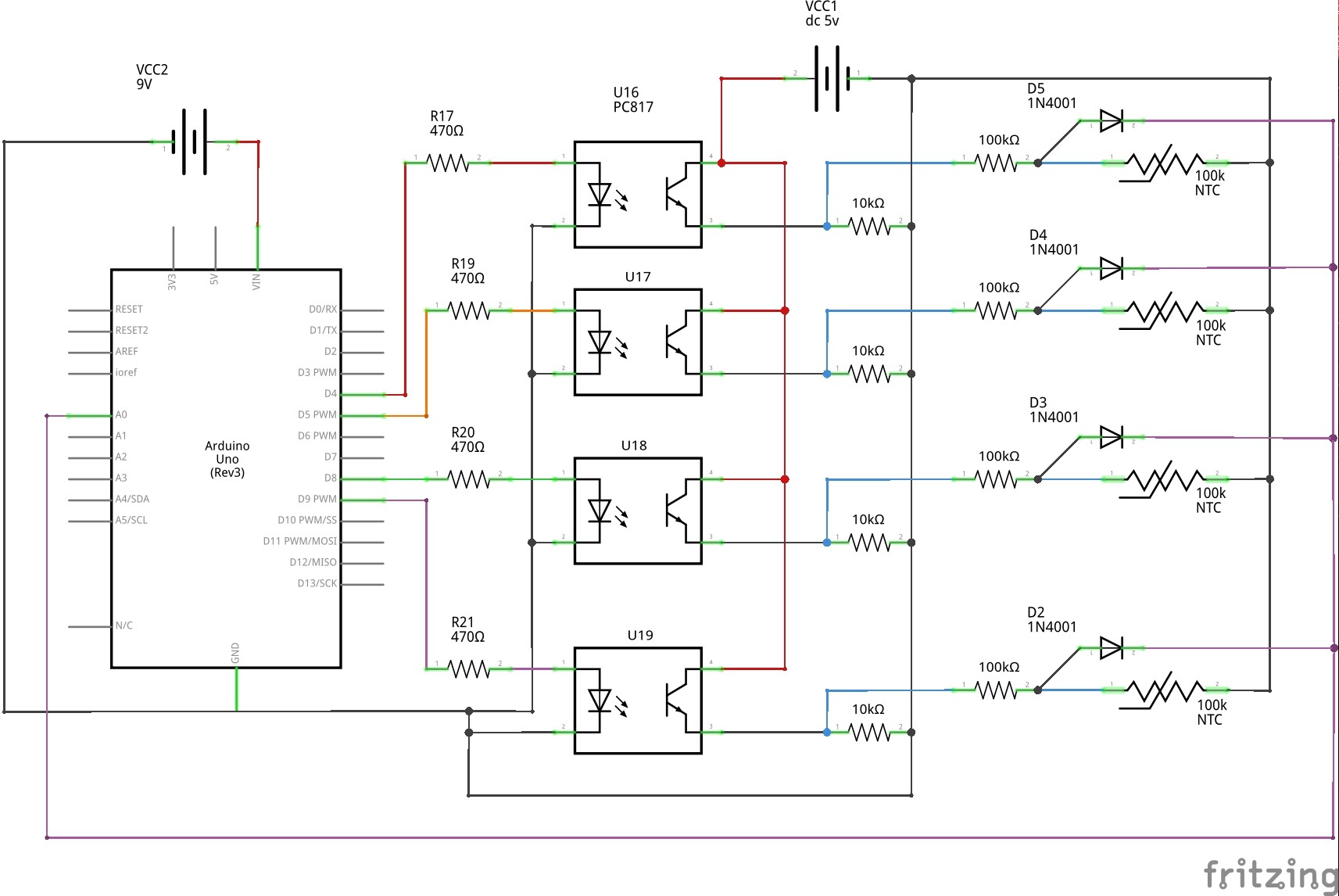
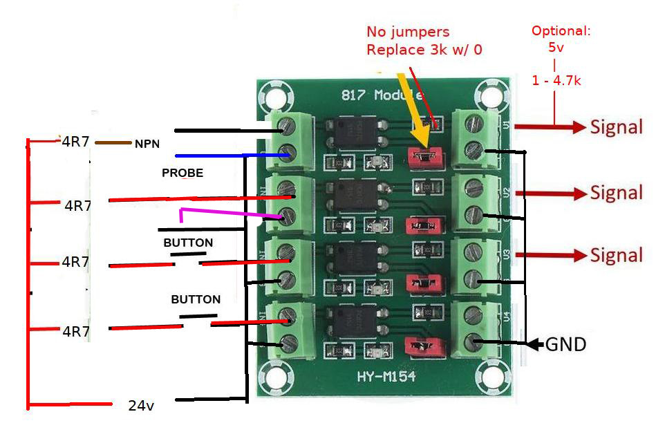
This circuit shows resistors on the input side of the 817s, maybe that is what I am missing?
This is not the circuit that I am using, it is just to show that resistors are being used on the input side of the 817s
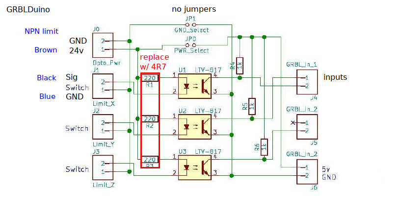
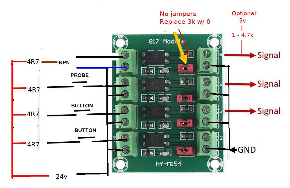
I don’t see any easy way to make that 817 module work. The GRBLDuino boards you were using would work if you replaced the 220 ohm (.11w @ 5v) input resistors with 4.7k (.12w @ 24v), the 1k pull-ups should be fine.
It took me a while to get the common anode input and switching to ground, e.g. 24v > 4.7k > PC817 pin 1, pin 2 is NPN signal or switch/touch plate + (switching to 24v gnd completes the circuit and triggers the PC817), pin 4 is the Arduino input which can have a 1 - 4.7k external pull-up (I’ve had no issues with just the internal pull-up), pin 3 is Arduino ground. Images already posted: Sometimes I get this happening - #12 by dalrun… Updated GRBLDuino image
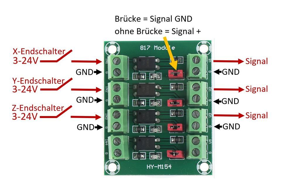
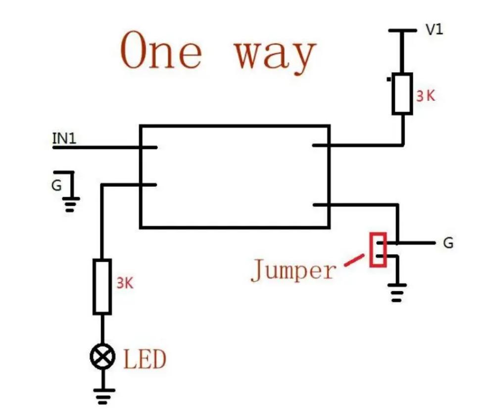
It’s kind of weird. It says that if you have the jumper connected, the red signal arrow is gnd (as well, it seems), without the jumper it carries a positive current.
What I now see is a common cathode board with a huge ground plane. It looks to me like the input G terminals (via resistor/LED) and the output G terminal jumpers connect to the ground plane. I’m probably going to get myself in more trouble with this (gonna delete the last try)… I’m not an electronics guy, but the 3k G resistors would seem to negate the need for the 4.7’s in my image.
Thanks Dave, I will check it out.
It is strange how the jumpers are used,
I have never worked with SMD resistors before, but willing to give it a try. I have 8 of these boards, so copping one or two up is not problem for me, it could be worth the experiment.
I found I still have a few of the GRBL Buffer boards as well, so I will try using those when I get back from my trip that I am going on today, back on Sunday.
I take that back, it looks like all input G terminals go directly to ground. I’ve only had experience with common anode hookups so take that image w/ a grain of salt.
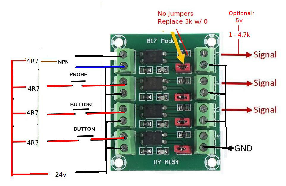
I see another problem also, the probe doesn’t short to ground, it will be shorting to positive. A work around would be to break the ground connection and hook up the probe to the ground terminal of the board and then it would work I think.
Seems like this board is a bit useless all round, and yet there are so many being sold.
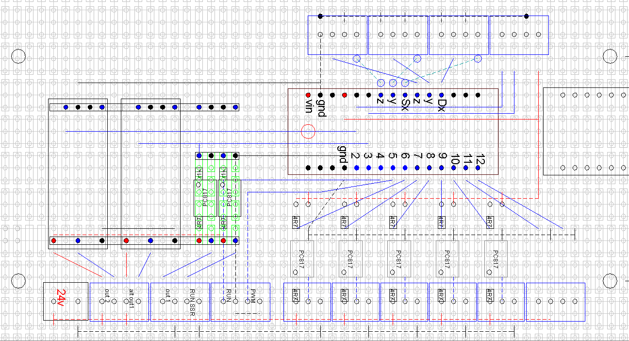
This was my thinking, showing the polarity a bit clearer, and also my thought on the work around.
I may be totally wrong, but need to find a solution for this.
When the above switches are open, 24v doesn’t go past the switches and the 5v Arduino inputs don’t go past pin4 on the PC817. Closing a switch lets 24v run through the PC817 to GND (24v) which triggers the PC817 so that 5v can run to GND (5v) and trigger the Arduino input. Switches can only be in front of the PC817, everything after is GND.
You’re right that it (common cathode) may not work with a probe switch because the PC817 probably needs to be in front of the switch (common anode) so that tool = GND (unless its a 2x insulated router), i.e. 24v > 4R7 > PC817 > plate > tool > GND. An NPN switch could also be an issue if the signal/Black wire isn’t strong enough to trigger the PC817 (common anode has 24v to all PC817’s). It’s looking like a common anode capable board is the only all purpose way to do Estlcam inputs.
Wow there are a lot of variations to this board. But the Hy-154 that you show the red jumpers are for isolation between input and output grounds. Remove the red jumpers to isolate the imput from the output. Which you really should as your using 24volts on the input switches
It looks like I may have done my dough again with these 817 boards.
I looked for the Estlcam board but was not able to find it again, I think it was available through the ArdunioClub and I think it was about $50USD plus postage.
I may have to design my own board again adding the mosfet switches, 817s and VFD circuits and order the boards from PCBWay. They will make 10 boards for $5 and always supplied me 11 boards, freight is much higher and works out about $30AUD for 11 boards.
The rest of the electronics I probably have in stock already, so it makes sense to me to go that way.
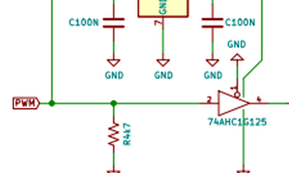
I decided to make my own board and had to order some 74HC1G125 ICs but when looking at the circuit was confused with the pin outs for it.
I believe it has 5 pins, can someone please verify which pins are which (maybe only 3 pins are used?)