So reprinting, because of a couple of errors and inconveniences.
I can’t easily reach the buttons on the control board. Since this is where the focus/on/off button is, that’s not a good thing.
Somehow, I managed to be 2mm off on one dimension for the screw holes. Not sure what I was looking at, but my calipers and the sketch dimensions did not agree, so I fixed that.
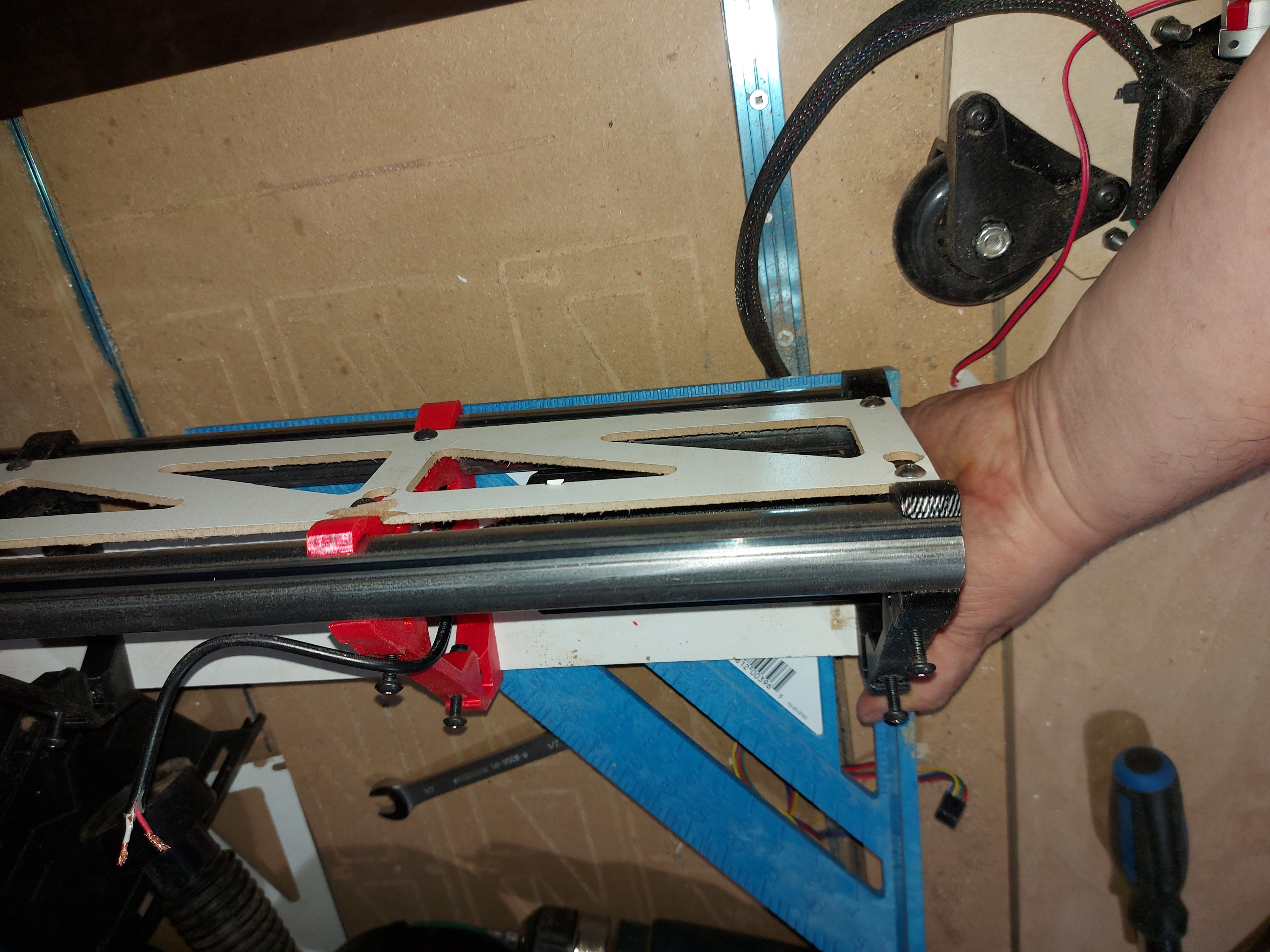
The clip on the router was allowing a bit too much movement. I extended the arms a little, and increased the Z dimension to 27mm (Which is what I measure the space between the tool mount rings as.) It’s my hope that a tighter fit will result in less possible movement.
Thanks, I’d considered that, but it’s not really practical, since the vac hose is zip tied to the tool mount.
Though it occurs to me that the upper vac shoe is the reason why I drew this part up, sicne it wouldn’t allow the laser heat sink to go low enough, it could probably be edited to allow it, and have a part to keep the air redirection from the router… Or the upper vac shoe could have a bracket for the laser, since it’s firmly bolted to the core…
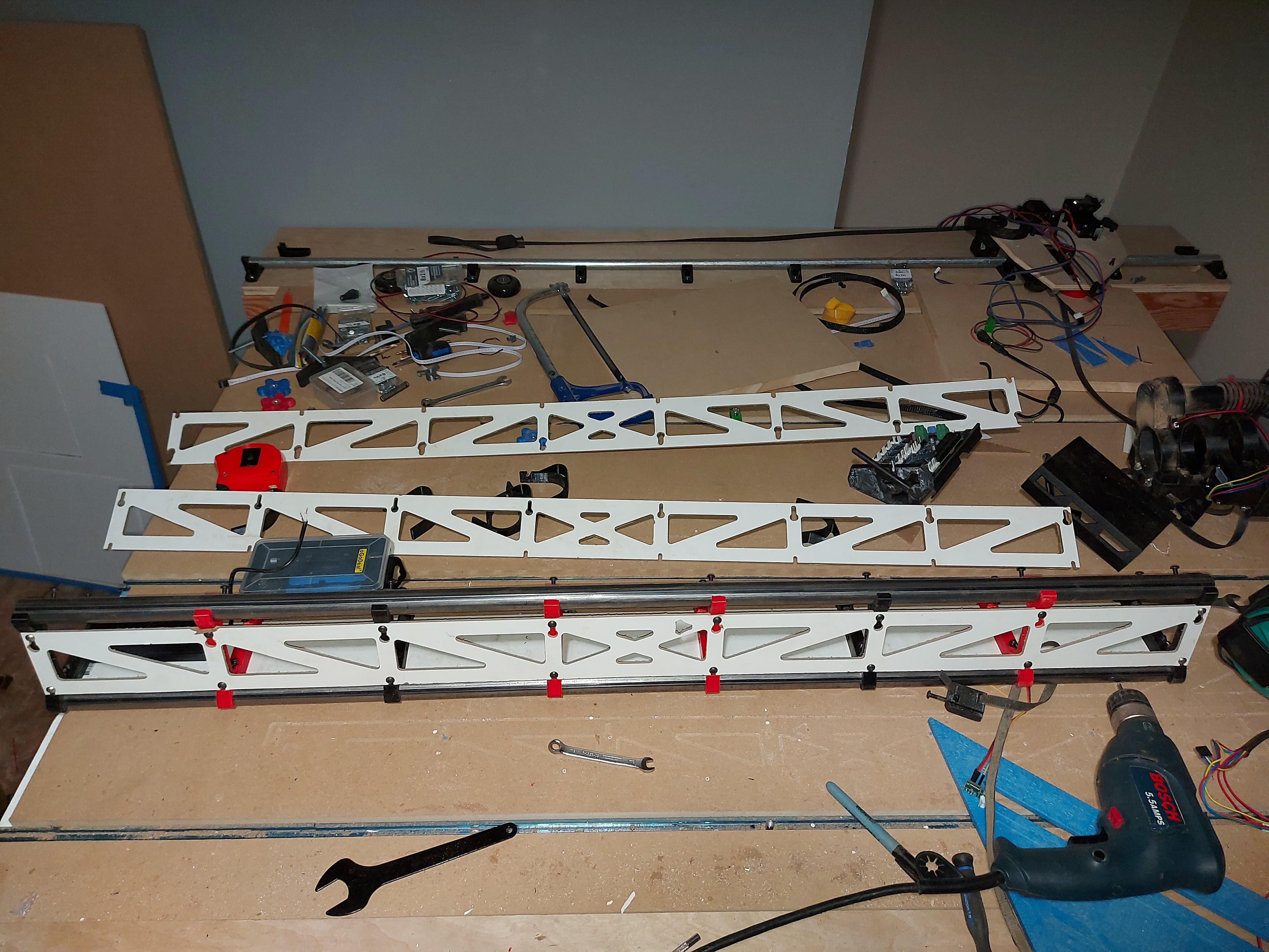
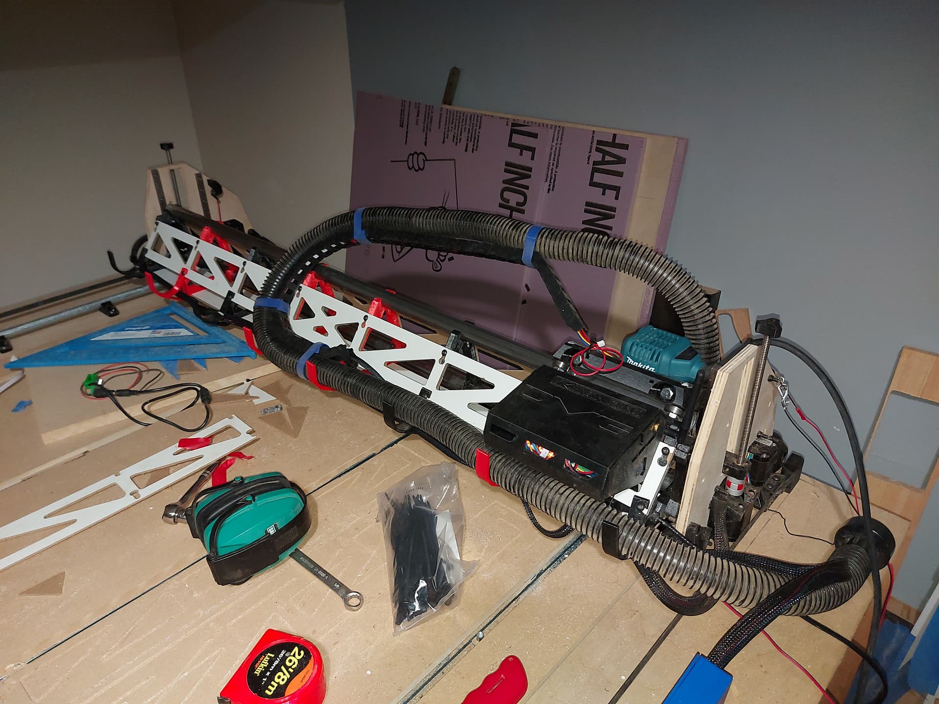
Still 4 more braces to print, but this looks super stout already. Once I cut that steel to the shorter span, it’ll be hard to go back to a LR2. Fortunately, I have no plans to look back.
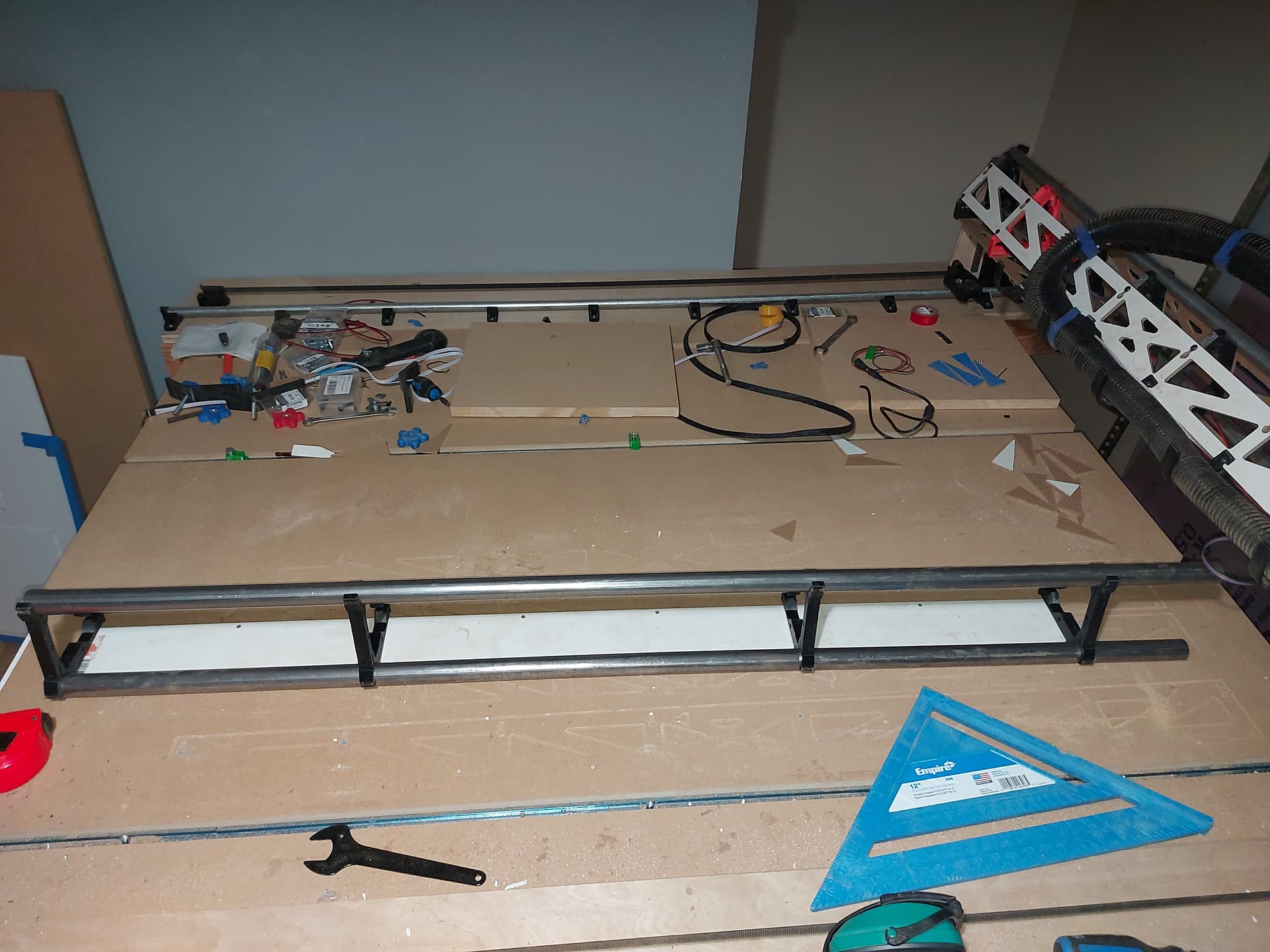
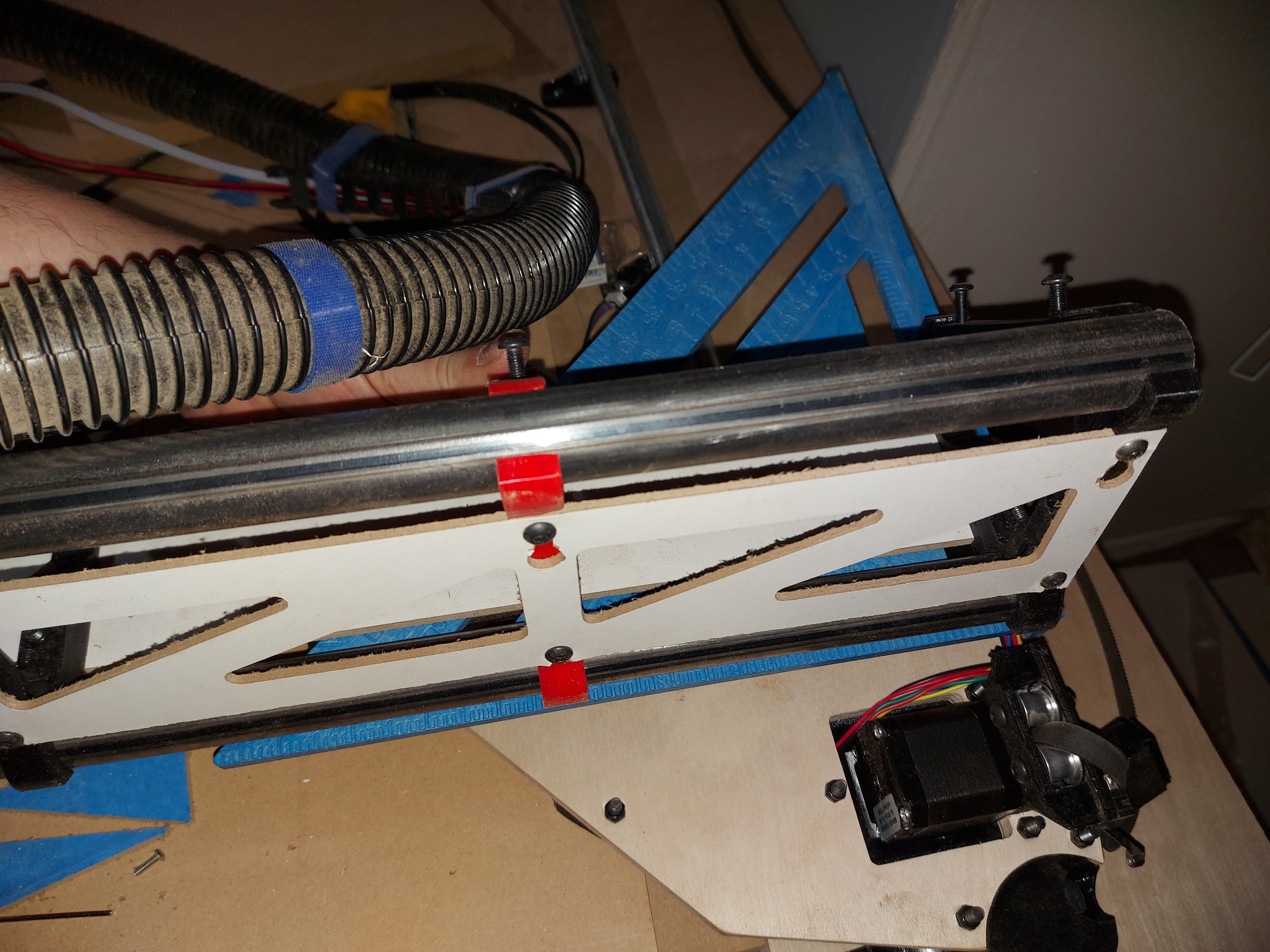
New beam assembled with bottom (solid, no keyholes) and front strut plates on. Re-used the 1/8" front plate, and will re-use the new rear sloped 1/4" plate. Needs wiring up first.
Checking the beam corners for squareness. With the square tight to the edge, I can’t see any discrepancy when comparing to the steel. (The square seems to have slipped slightly in the photos… holding one-handed after all…) but it looks good. If it didn’t, I would re-do the bottom plate at least. I dont want avoidablr and predictable bad alignment, after all. (Actually, I might re-do that bottom plate anyway, a couple of the holes didn’t feel right on assembly, like the drilled holes were just a bit off. I did that plate with the drill press and table saw.) I want to add some features to rhe bottom plate for wire and power management, as well as potential air assist for laser, so this will probably be coming off again. Or maybe Ill just drill appropriate holes and let it be. I’ll decide if the alignment problems go away when this is bolted on.
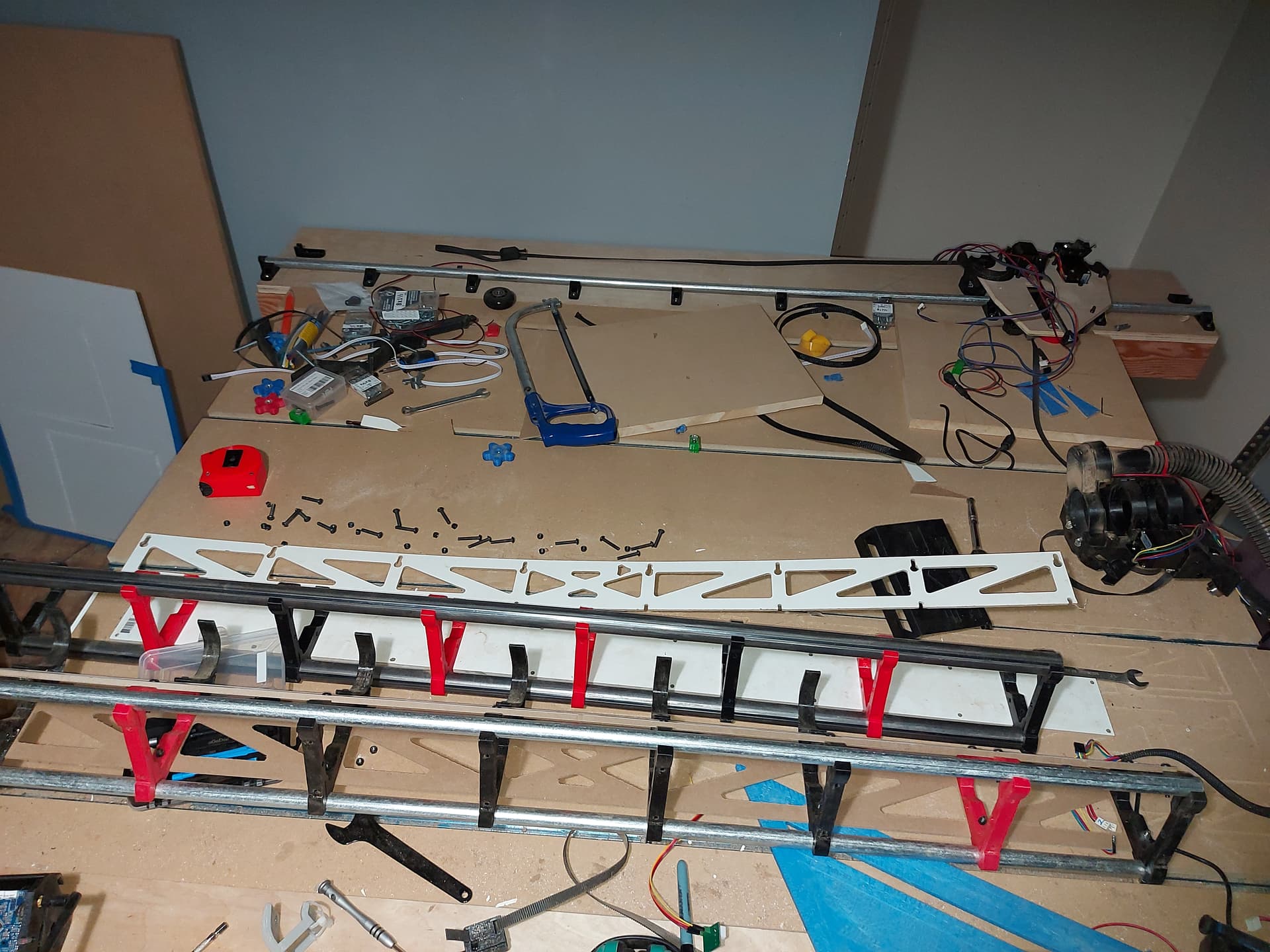
I ran my wiring through the inside of the beam, so I needed to pull it all. I did leave the vac hose on.
Kind of OK though, this will give me a chance to put the sheathing on the wiring harness. I also have all of the motor and stop connections labelled, so it won’t be difficult to re-do it.
I add the fake molex connectors (that have captive ends) on each motor and the JST-HT (I think?) On the board side. So I can remove them pretty easily.
The 7" PanelDue might be too big for this. Maybe I’ll switch the 5" from the Primo, or one from a printer for rhe 7". Had a bit of a.mishap printing the case, a bit of the face stuck down to the PEI too hard, and it broke off, but I can day that printing both top and bottom, plus the various clamp pieces is the single biggest print plate I’ve ever attempted. It only barely fit on the 310mm plate.
Try and get that hose and chain connected to the top of the Core. I gave mine a few good over bends and zipped it in place. That should significantly reduce the force near the endmill, and put it all up at the top two wide spread bearings.
Will do. It’s sort of fastened down with a zip tie that you can’t really see, bit a more firm mount is in production.
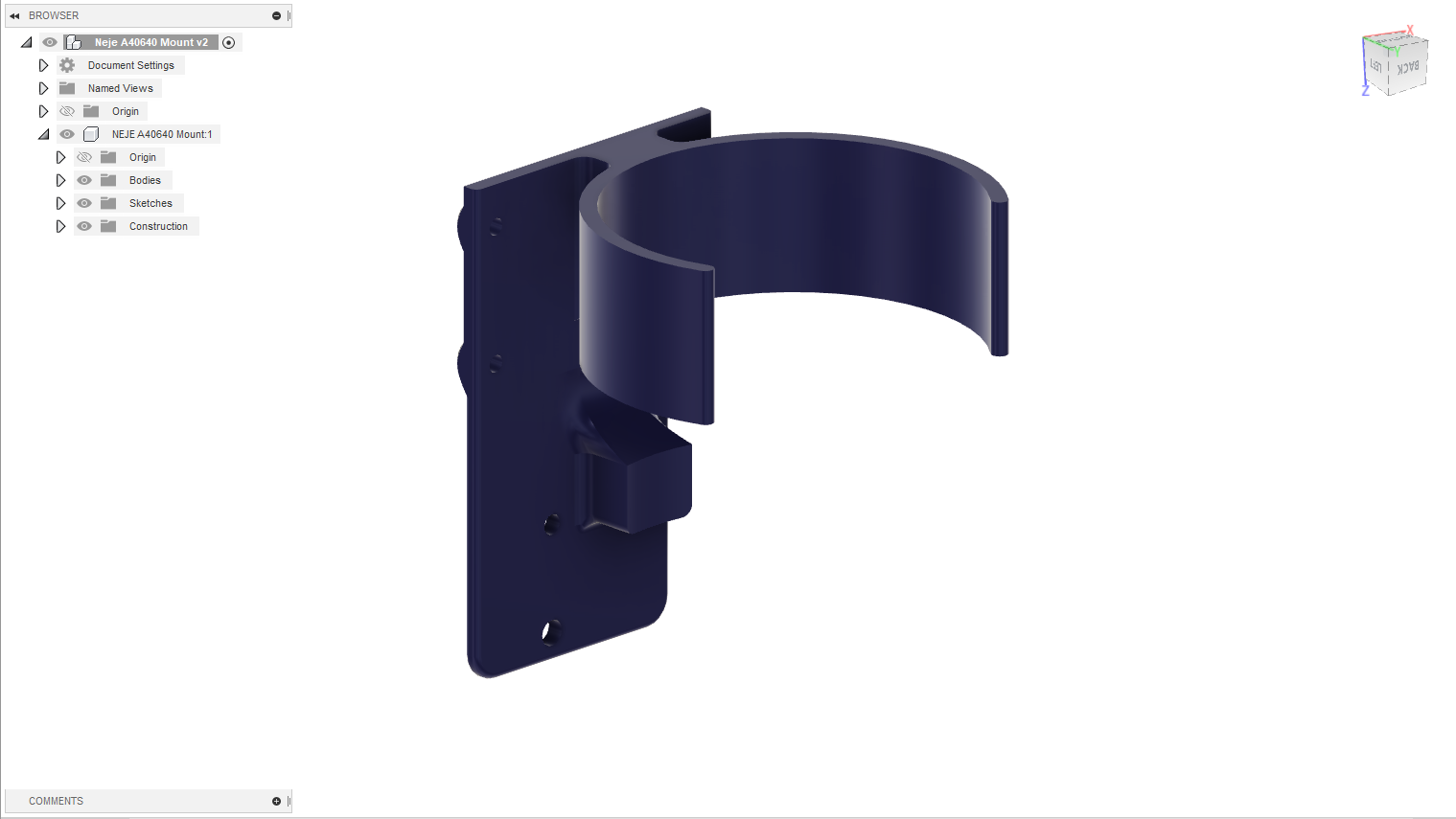
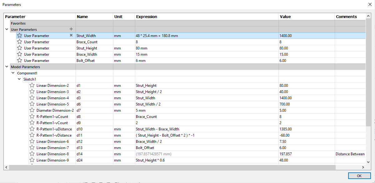
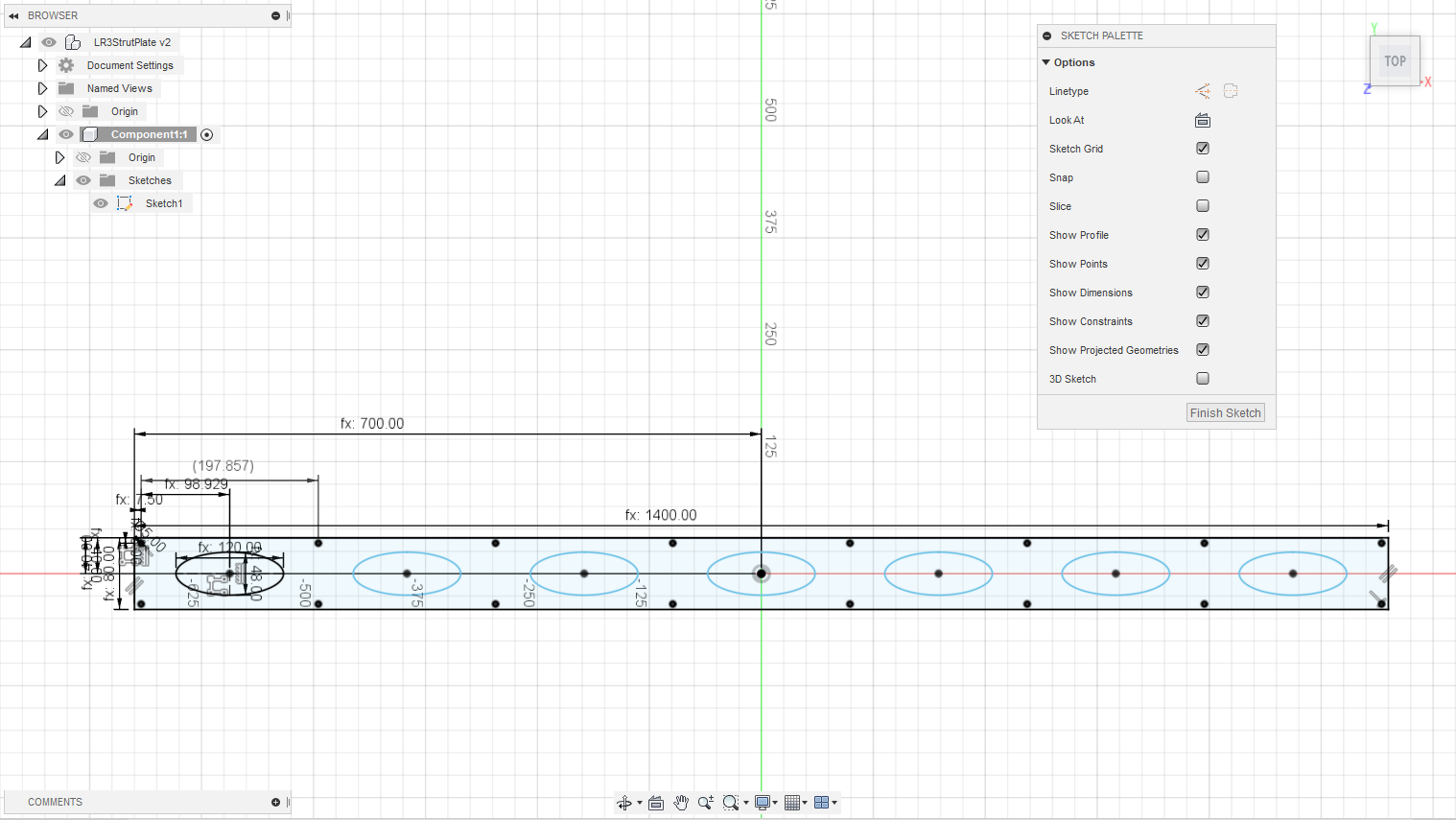
Meanwhile, I decided to experiment with Fusion360 parameters, so I decided to play with the LR3 strut plate. I want to re-make the bottom one that I have with hand-drilled holes, and not the keyholes, so, I made this one up
Of course I didn’t need to do all that for my specific case, but it was useful teaching myself how the parameters and various things interact, and let me define everything with equations.
I wasn’t actually planning on the ovals, but I wanted to try something.
In this sketch the only things hard-coded in are the bolt diameter (5mm), that there are 2 bolts per brace, and the ovals are 60% of the height of the strut high, and 60% of the distance between braces wide. Everything else follows from the user parameters.
It probably isn’t particularly useful, but it was educational for me.
Anyway, now I have a sketch to export to .DXF so that I can re-make that bottom “solid” strut plate.
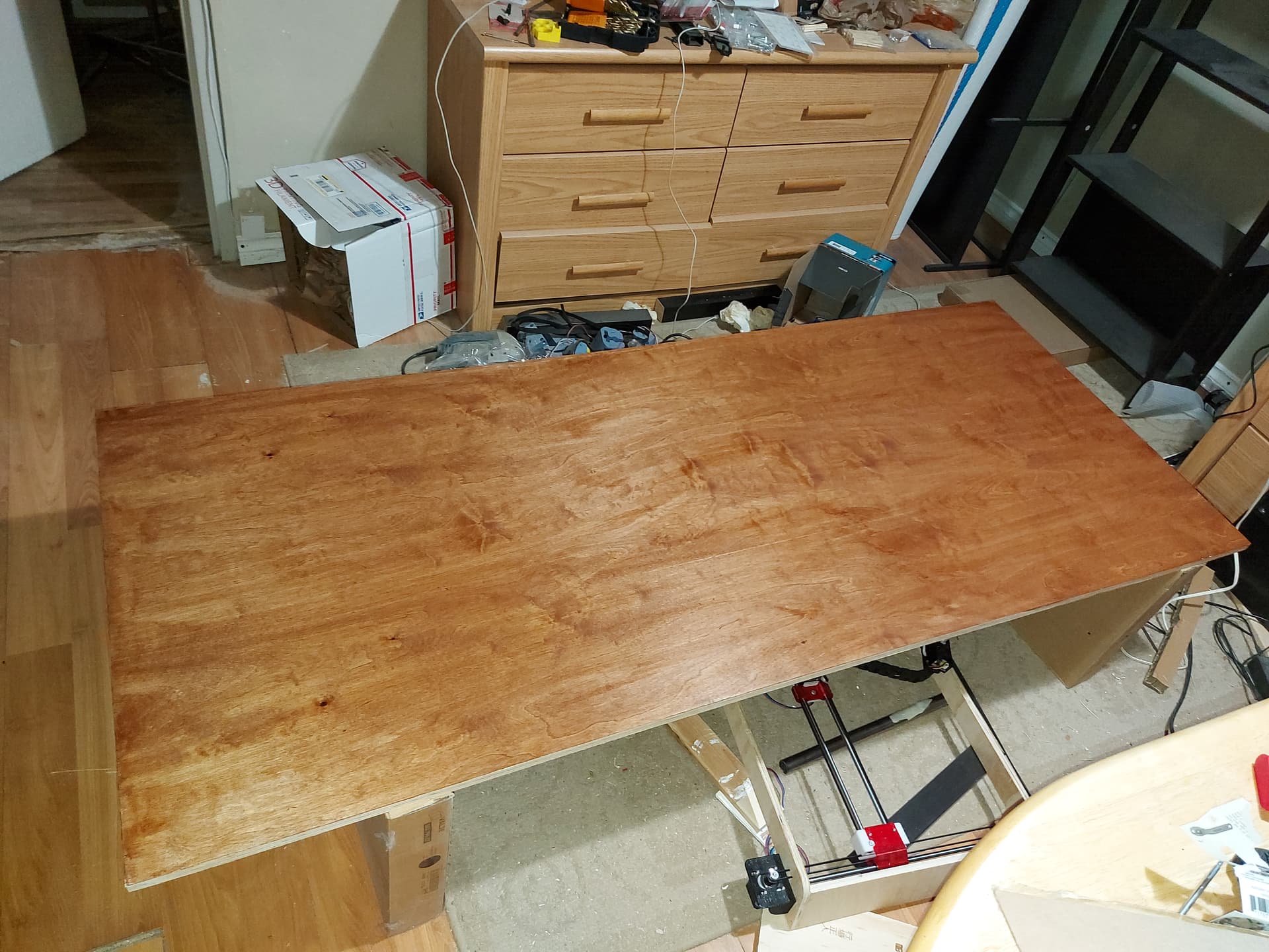
Well, I’m still in a bit of a hurry to get my office area set up, so I did just shove the desk in there.
Still need a good project for the LR3, thinking another ZenXY could be a good one. I have all of the printed parts, pulleys and belts, pretty sure I have motors and screws. I have a sudden surplus of conduit .
I think the only thing I’m missing is control electronics, but I will need to check for the optical endstops. I might need a bottom surface piece.
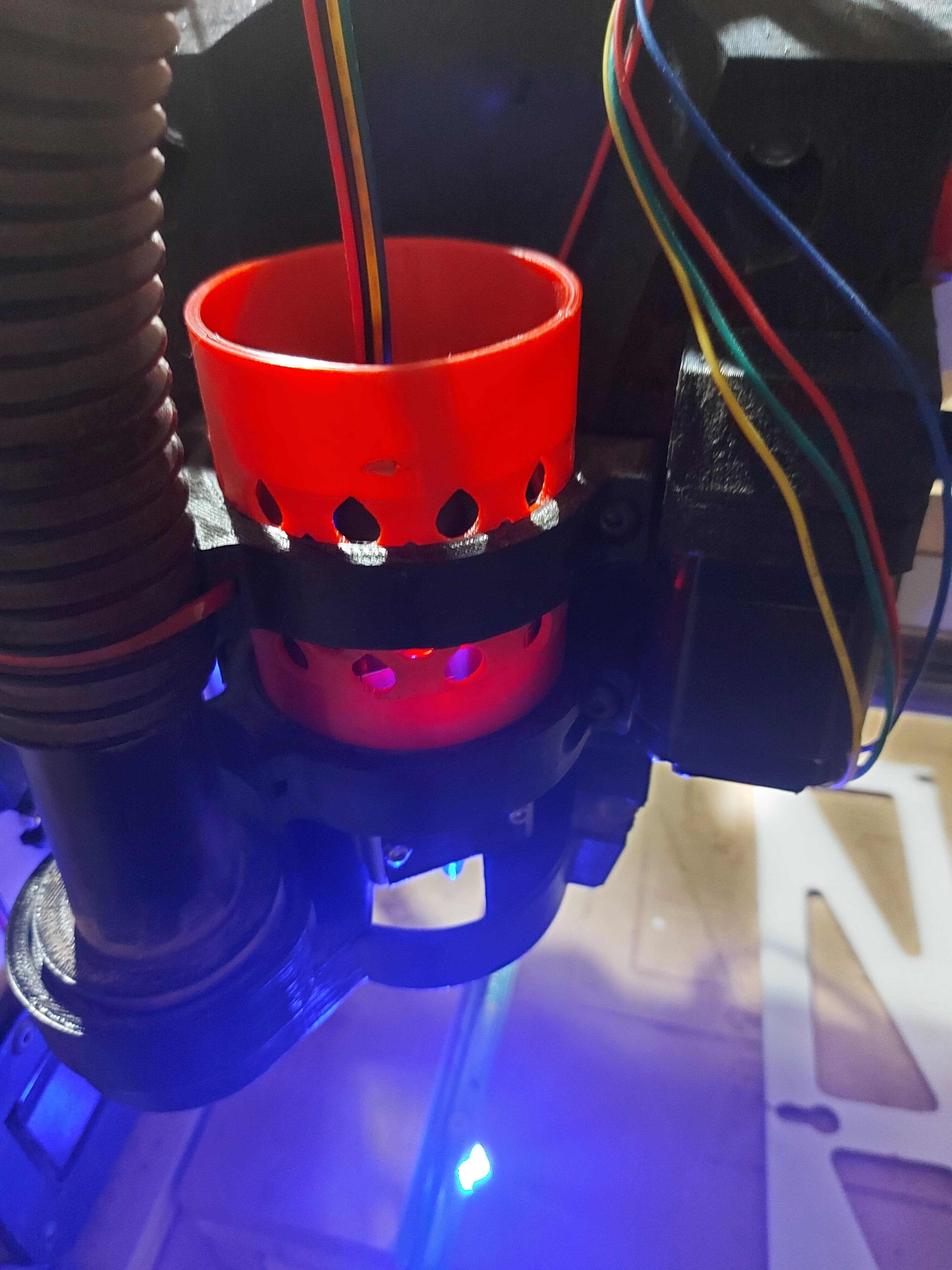
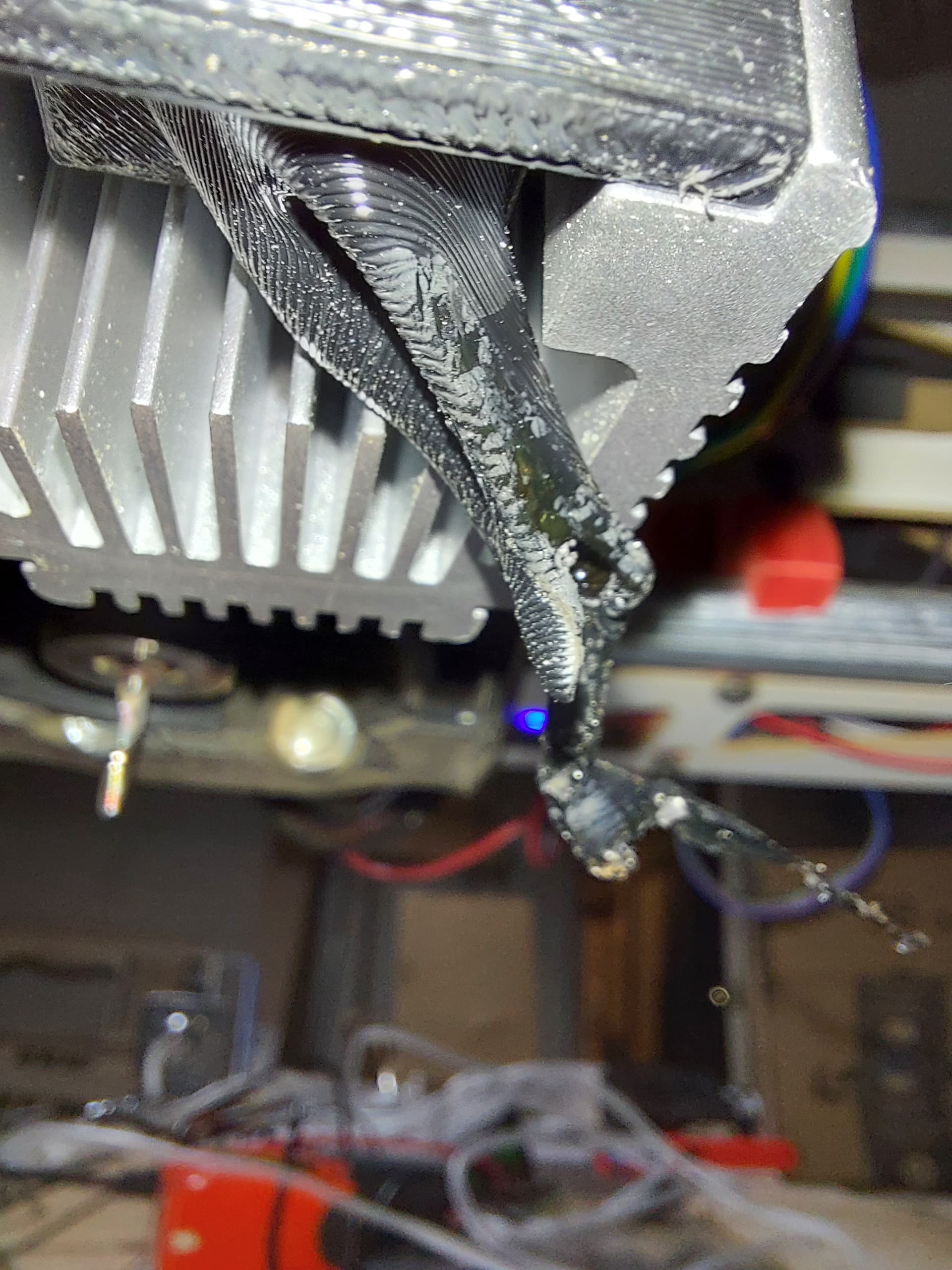
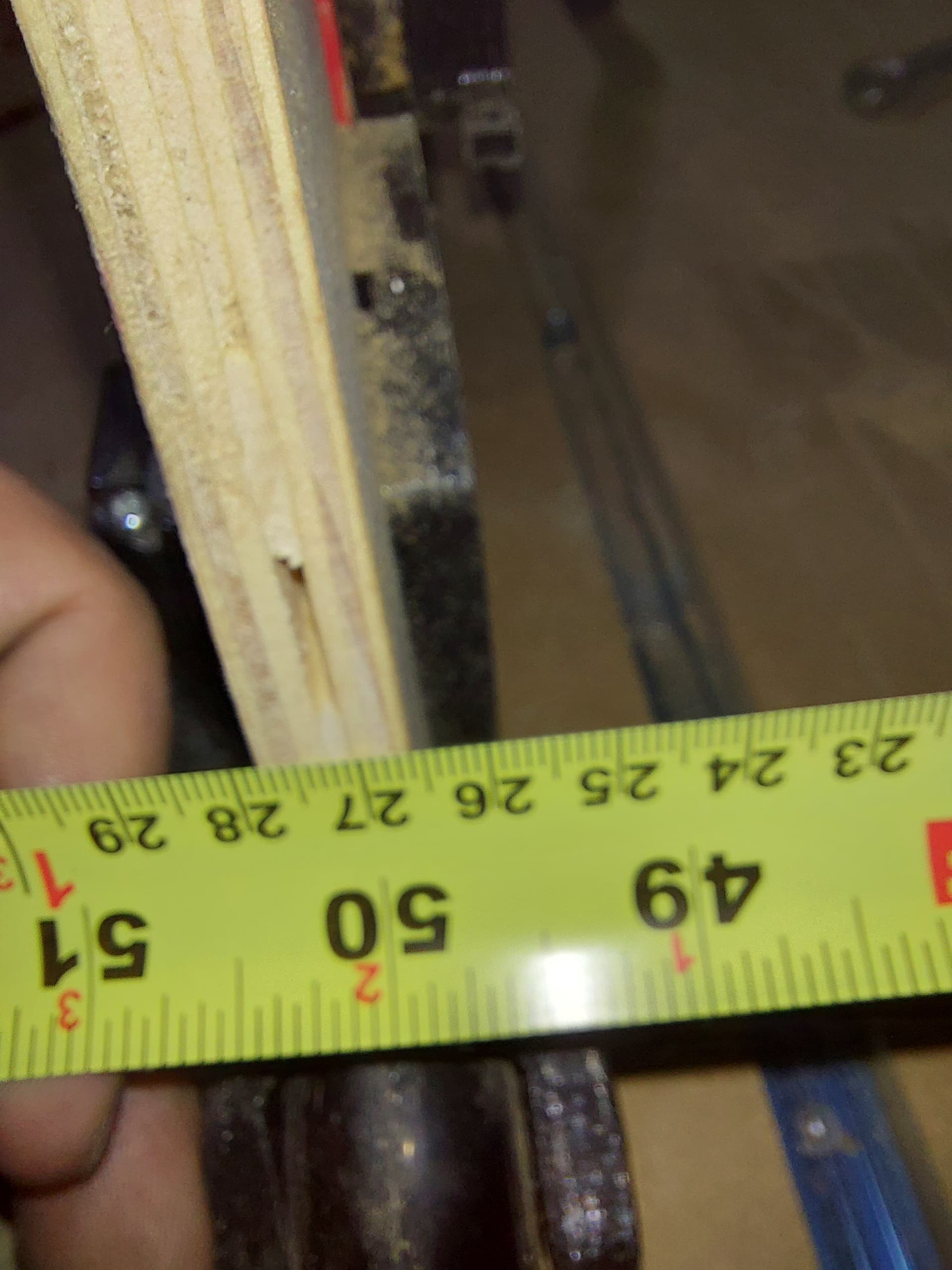
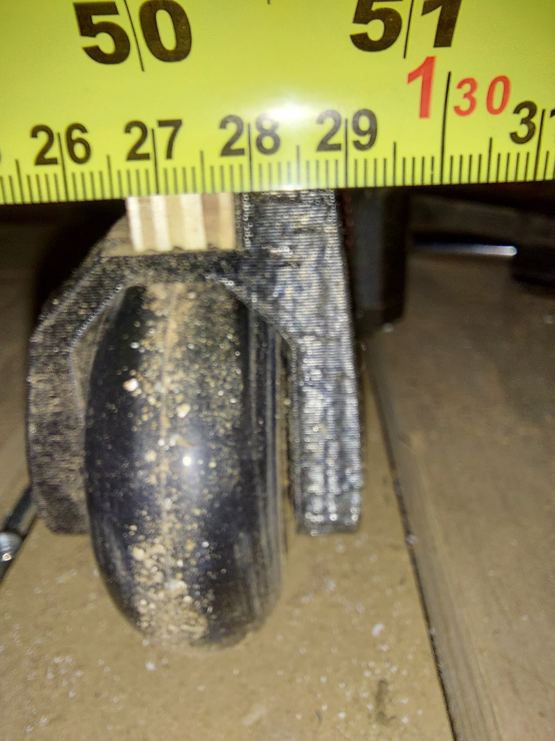
In this position, the air assist nozzle is about 1cm or so higher than the bottom of the core, and with the focus set to its longest, the focal point is just above the bottom of the core. With the core just skimming the surface, it might be OK, but probsbly no good for cutting thicker.material.with multiple passes.
@vicious1 maybe having the CAD for that part is necessary after all, to allow for the laser to sit where I want/need it. I would want the air assist nozzle about even with the bottom of the core ideally. I would probably cut the opening larger, and make a diverter plate for the router cooling air to snap in place when the laser isn’t there.
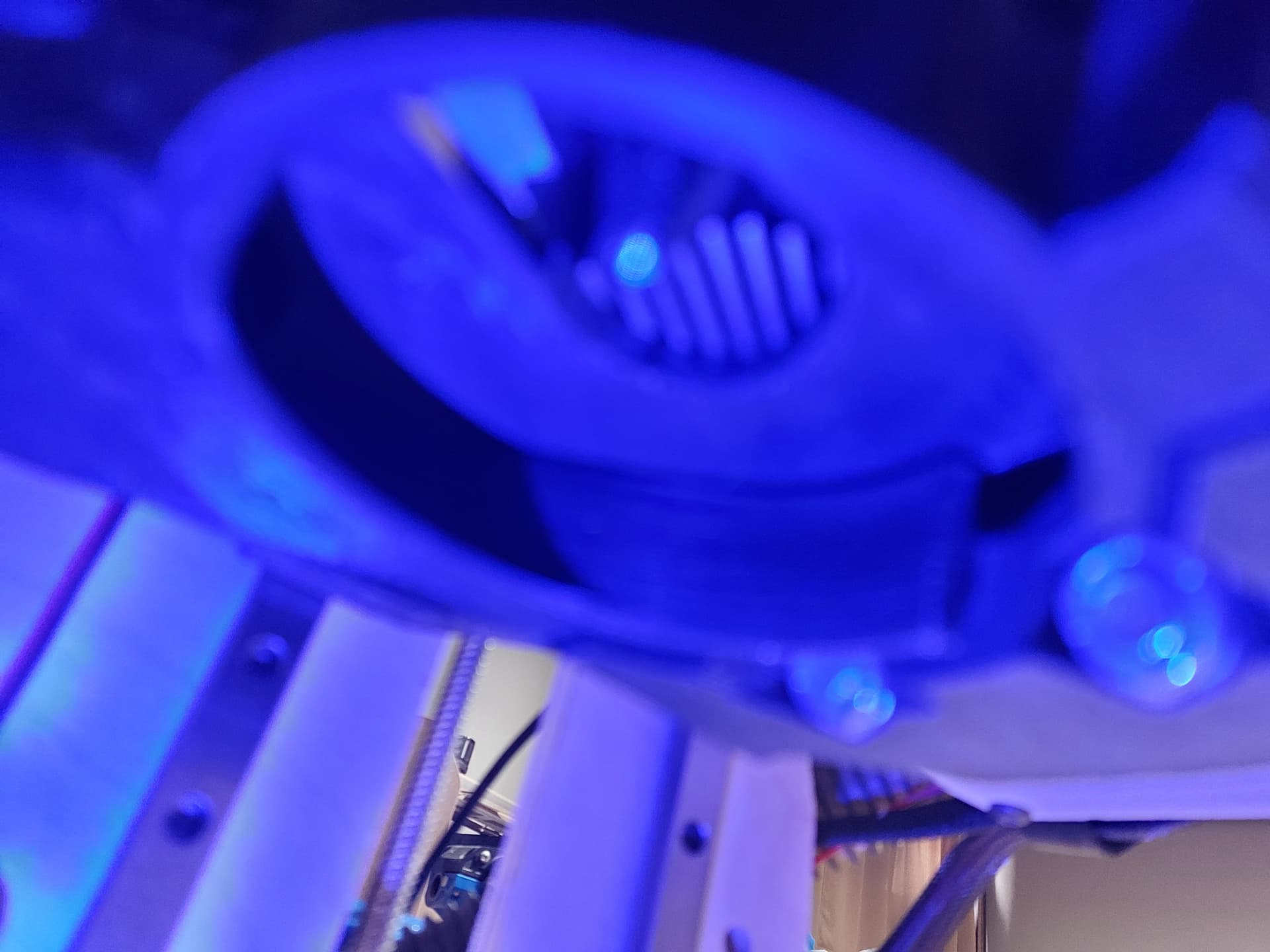
Edit, I had the laser glasses on… should have turned off thr 1% focus power for the photos…


 .
.