Even if you move the Z all the way up? I got mine in a few times.
At the nut holder?
Even if you move the Z all the way up? I got mine in a few times.
At the nut holder?
Hmmm. Maybe. I thought I had it up quite a ways. I think it’s just that I have an annoyingly long screwdriver for those. Removing the rail rider was fast and effective though.
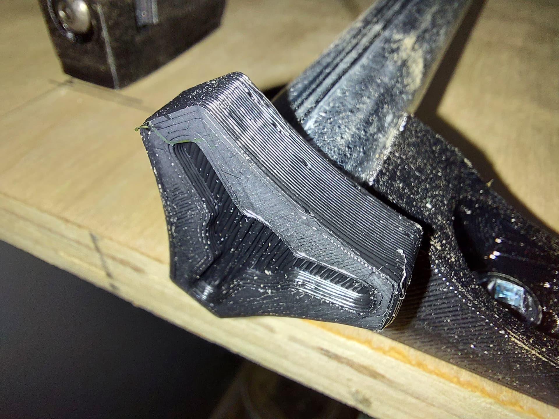
I think I wasn’t holding it well enough. It was cracked at the nut holder, yes, but also along the top portion where it aligns to the XZ plate. The result was a hot mess. I re-printed the part 2x at 50% and figured I’d “destructive test” one of them, just kind of gorilla it on and see how it fails… And it didn’t, so it’s still in place.
I threaded the Y belts in place, too. I guess I really don’t want to get my work project done after all. Procrastination central here…
Okay, decision time…
On the one hand, I have my Duet Wifi. I already have things like motor extension wires and switch extension wires wired up with the plugs that fit the Duet, so less crimping if I go this route. The problem is that the 5V regulator on board went pop on the last job that my LR2 ever started. (Strut plate for the LR3) As a result, that board needs an external 5V power supply, since me replacing the regulator is a recipe for disaster. I do have another board coming, but it’ll be 3 weeks or so to get here from China. (If it arrives at all. My luck with Chinese shipping isn’t getting better over time.) Keeping in mind that I will most probably want to run this machine permanently on a Duet board, this is currently where I’m at.
On the other hand, I have an SKR Pro board which is already firmware configured for the LR2, with the correct parameters already in place. (Except that it thinks that it has 200mm+ of Z, which is definitely not right.) Firmware is really no big deal, but for the SKR, I only need 1 power supply.
I suppose that I could just yank a Raspberry Pi power supply and use that, the Duet responds when powered over USB… just need to get an extra plug-in over to the table, or just spend the $15 for a 12V-5V converter…
I suppose that the real tipping point is that I need the SKR Pro for another Repeat build, which I intend to be one of the first projects for the LR3, and I intend to be using a Duet for the LR3 in the long term. Plus, I really hate crimping wires, so the less of that that I have to do, the better.
I was supposed to have the NEJE A40640 laser, but… Chinese shipping. (Although the actual error was much more local. Ship a package from the other side of the planet, and it ends up missing its destination by maybe 60m.  ) I hope whoever has that laser enjoys it. I’ll be running a wiring harness for the laser as well. The LR3 doesn’t look like it’ll be as convenient to swap tools as the LR2, I wont be able to just unclamp the router and swap in a laser. I suppose that I’ll have to design something to clamp or bolt onto the core, but I feel that the laser module should be removable so that it doesn’t get chips and dust on the lens.
I think an extra power supply is no big deal, most 5V at tiny wall warts. There is plenty of room in or on the back of the beam.
I ended up with a bunch of 12v to 5v buck converters for a few dollars if you wanted to go the smaller route.
As for the Laser, Just design the laser mount to fit in the circle of your router mount. It is a very easy swap. You can even use the VAC to blow the smoke outside. I have taken the router off several times by just loosening up the screws a turn or two.
I have been looking into just mounting a small power strip, probably a IOT strip so I can only run one power cord to the beam and have control of the router and vac. I am wanting to automate things a bit more these days.
I am fairly certain I will be doing this soon.
I’m excited to try the one I made for the DeWalt/neje. Robert made one for neje/Makita.
I’ve already printed one for the Neje/Makita. Too bad the Neje got delivered ro the wrong doorstep.
That is a fricking bummer, I’m sure you will get your money back and a have a new laser module soon.
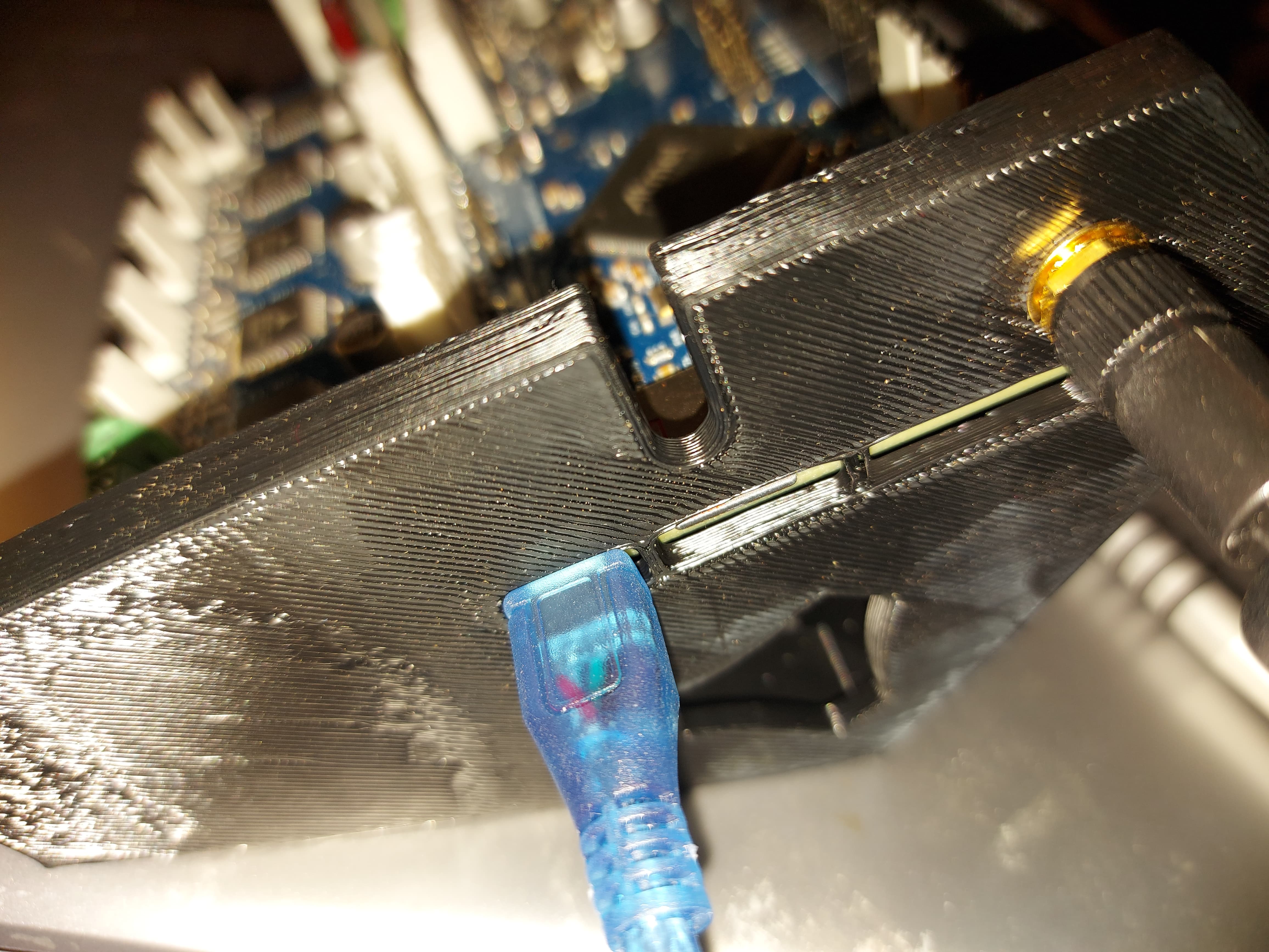
Pretty sure I agree about the power supply. I havr a buck boost 5V converter comijg that can supply a couple of amps, so I finished my remix for the Duet control board
Tested fofor board fit and that I can use the USB port
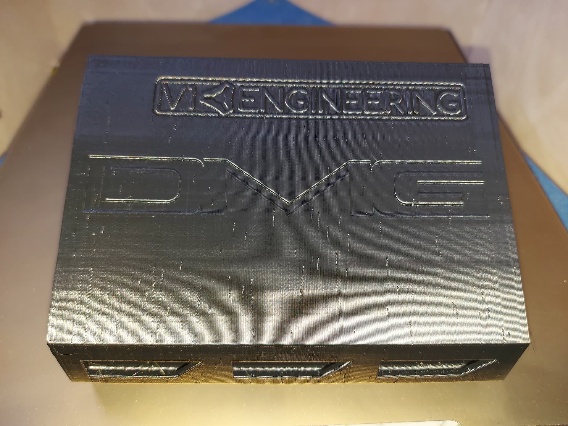
I originally grabbed the model with the on-board antenna, but this one has the external antenna, so I added a mounting hole for that. I left the room for the on-board, since that’s what I’ve got coming for a replacement. It’s also coming with a 7" touchscreen, but we’ll cross that bridge when we come to it. I’m using a 5" with the Primo. I think the 5" might be a better fit for the LR, because it moves, but I can swap them after.
I added my initials/logo to the case, since it’s my remix, but wanted the V1 logo on there too. I’d have added the Duet logo for this mix too, but couldn’t find one that I could convert to svg or dxf easily.
Changes to this case from before, I stretched it to 150.m in length. This gives me almost 25mm inside the case at the edge for wire management, an increase of 18mm. I added a row of vents to the lid over the drivers. Not quite the same as Ryan’s, i made some different choices there. I’ll also ve designing the LCD holder differently, probably using the slot for the LCD cables as a mouny point. The PanelDue only needs a 4 wire interface, so no need for the capacity to hold 2 10 wire ribbon cables. I also dont have anything as slick as that hand-held LCD case around, so no need to accomodate that.
I will need to test all 5 motor channels…
A more compact power supply is en route, I should have in the next day or two, as well as my 5V inverter. I have both 24V and 12V coming. I think I’ll power the board and motors on 24V since it seems possible that this could maybe cut faster than the LR2, or at least I might opt for faster travel rapids. I never tried to get better than 2400mm/min from the LR2 ever, so 12V wasnt harming anything. I’d like to run the same Gcode I currently run on the Primo with this.
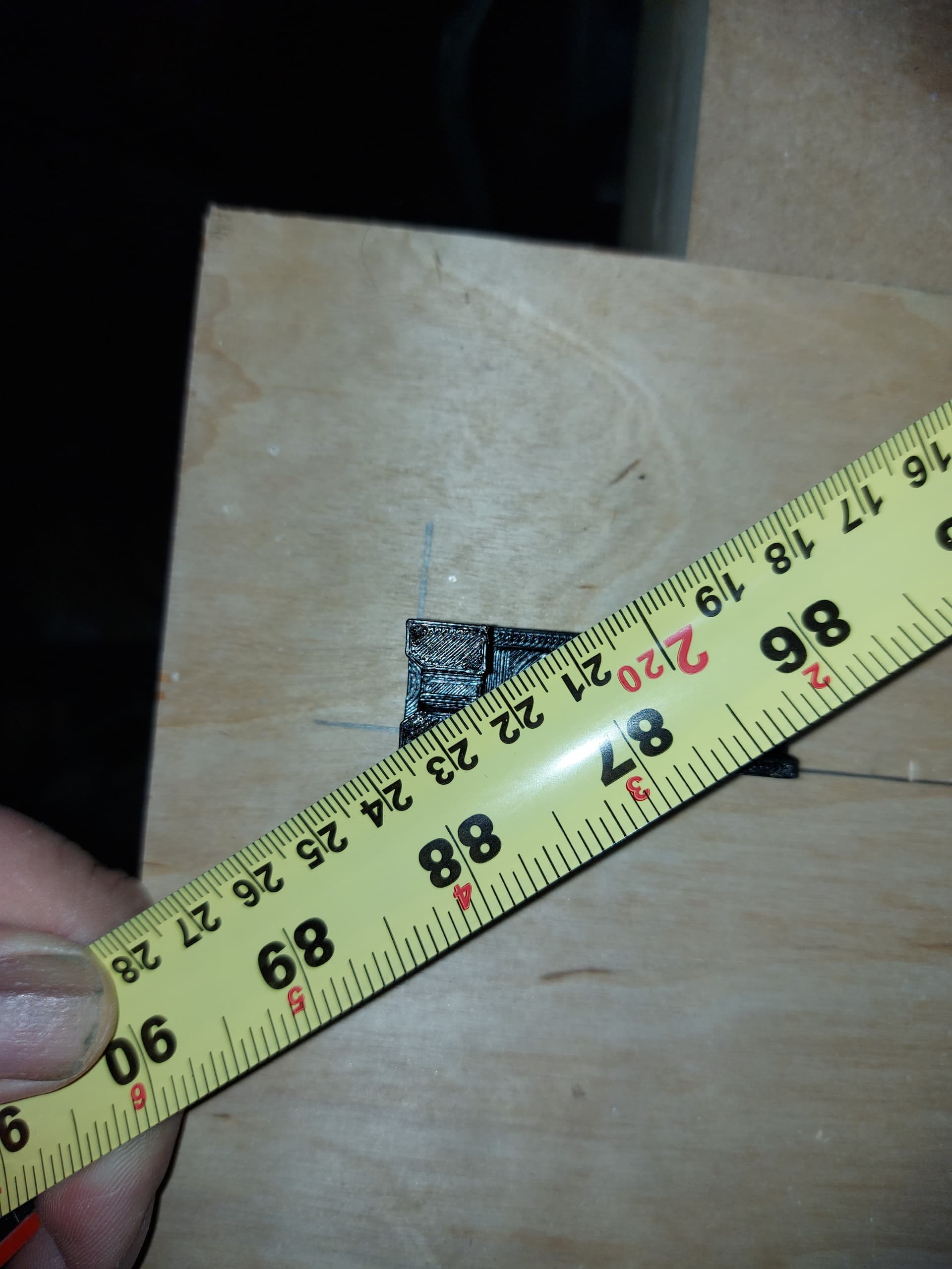
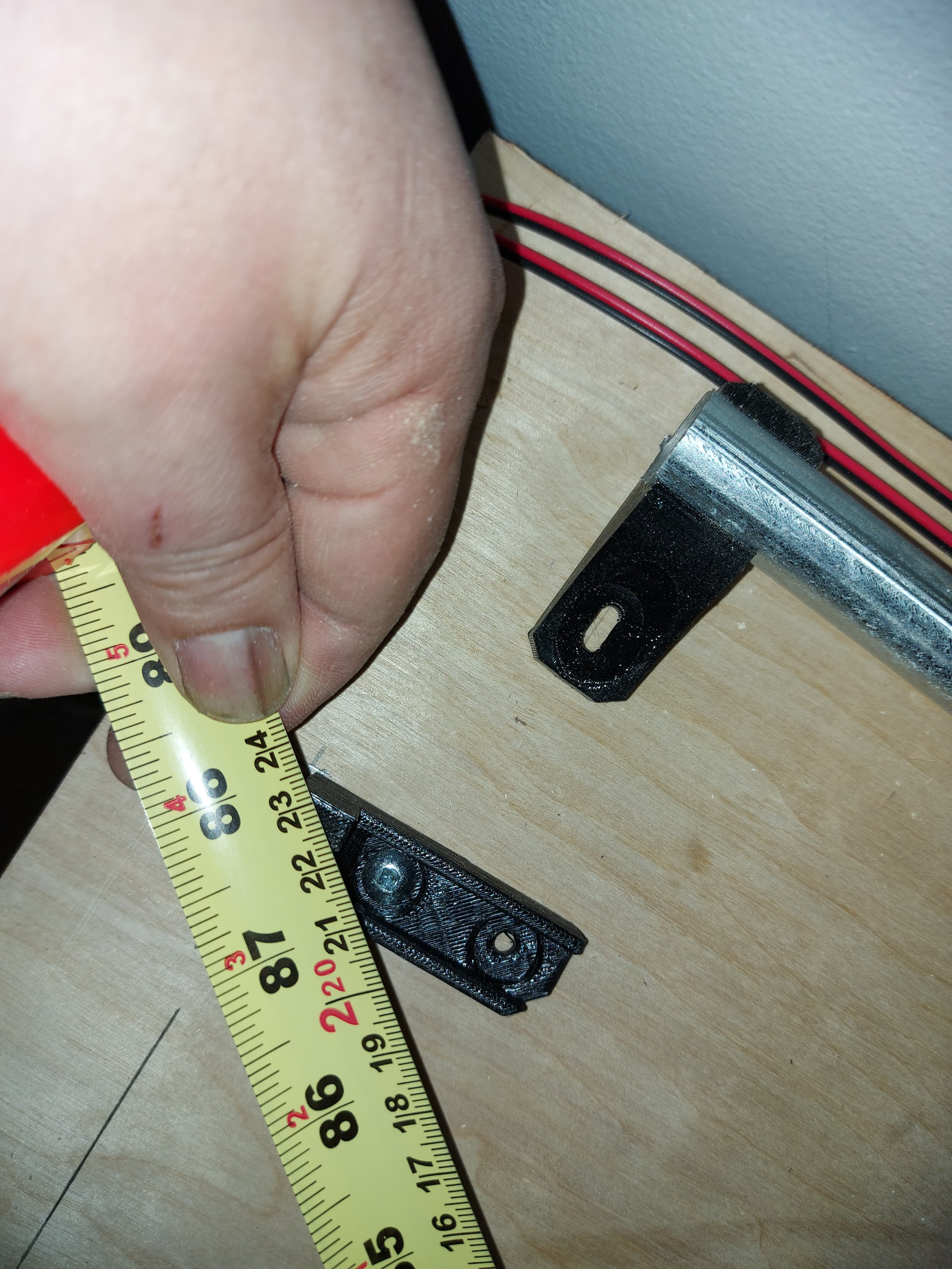
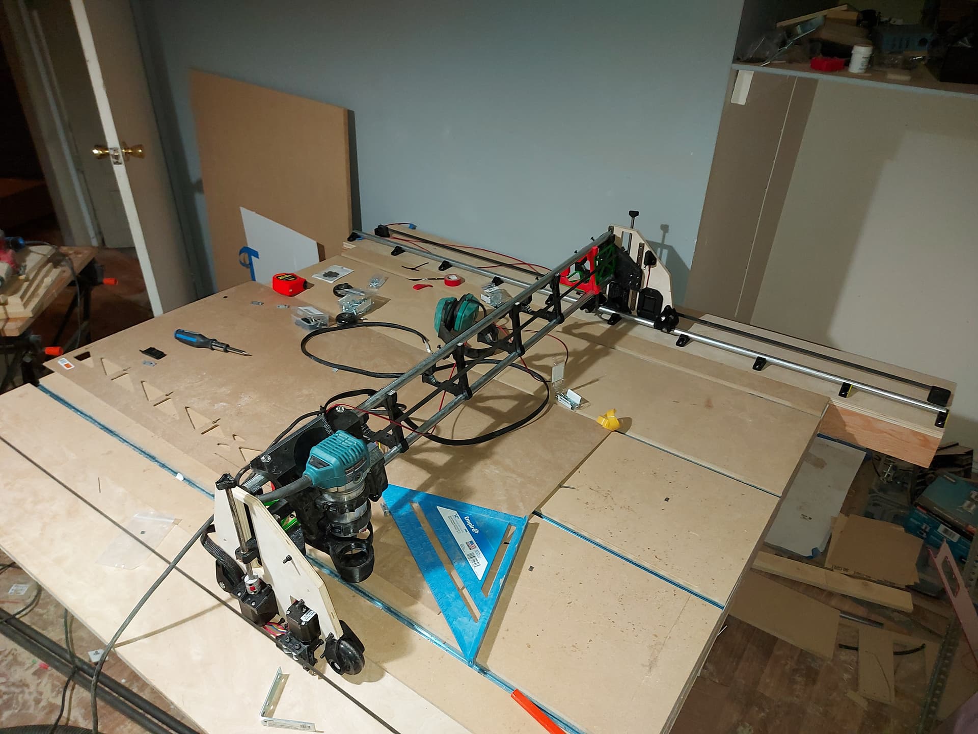
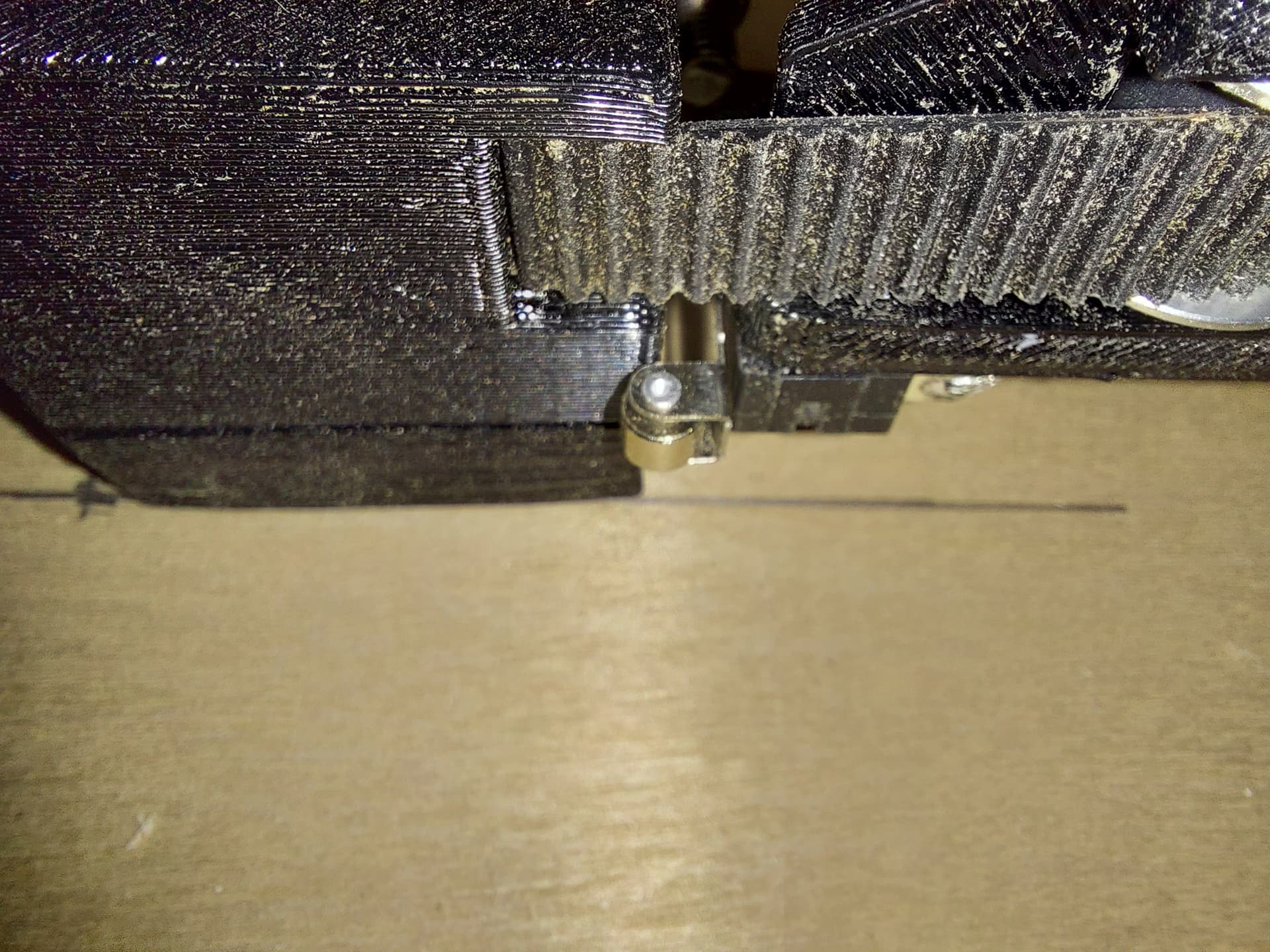
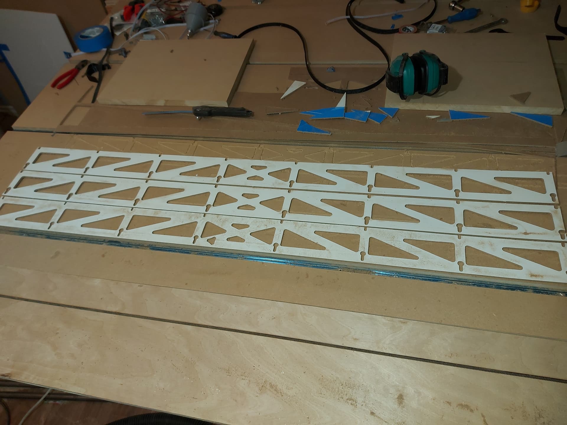
So, I squared up the belt holders
Then I checked if my math was good for the width
And, just for fun, end caps for the conduit.
I have my roller switches outside the part, and the metal is the only part that hits. Might need to rework that.,
Yes, I had the same issue. I even replace the end-stop with one without the roller and had the same result.
I am still getting great accuracy, I could move them in a bit I think. It just starts to make them hard to assemble.
Did a little work on the vacuum attachment today. I had a small problem. The vac hose that I have was bought to fit to the LR2 attachment, which is considerably smaller than the one for the LR3, so I drafted up a little ring that put a slightly tapered hole into a slightly tapered plug. The plug fits tight into the top part of the var part, and the hole fits the 33.x mm hose end that I have. Squished them together, and it works.
Of the 2 router clamps I printed, it turns out that the zip tie holder in one of them has something in it making it difficult to get the zip tie through, and of course, it’s the top one. (The bottom one the zip tie goes through easily. Figures. Anyway, I managed to finally wiggle it through, so now I have the hoses done. Now I just need to wire it up and I’ll be good to go.
I’m spending more time than I normally would on wire management and planning. I want this to look better, and since I have to do a lot of crimping anyhow for this project, I figured that I’d rather do it once, nicely than have to do it twice. There’s a little variability, since the current location of the control box is not going to be its final location, but it will only be moving a few inches from its current location. The difference between the length of the temporary strut and the permanent one.I just need to make sure that the wiring can handle that change when I set it up.
I do also want to set up the wiring for the laser at the same time, even if the laser isn’t here.
What I’ve seen is the laser needs a 3 wire interface to the board (+12V, Ground and PWM) which goes to its control module, and then a 4 wire interface to the laser. I think that the 4 wire interface is the better one to stretch, and have the control module mounted closer to the main board, though I think the 3 wire interface is probably easier to stretch. I’m not sure which side is less susceptible to interference and noise, but I think that I’ll extend the 4 wire harness with 18AWG wire, which ought to be thick enough to handle the power with minimal losses. It’s not like anything is going to have a truly fixed mount on the LR3, but moving in 1 dimension is better than moving in 3.
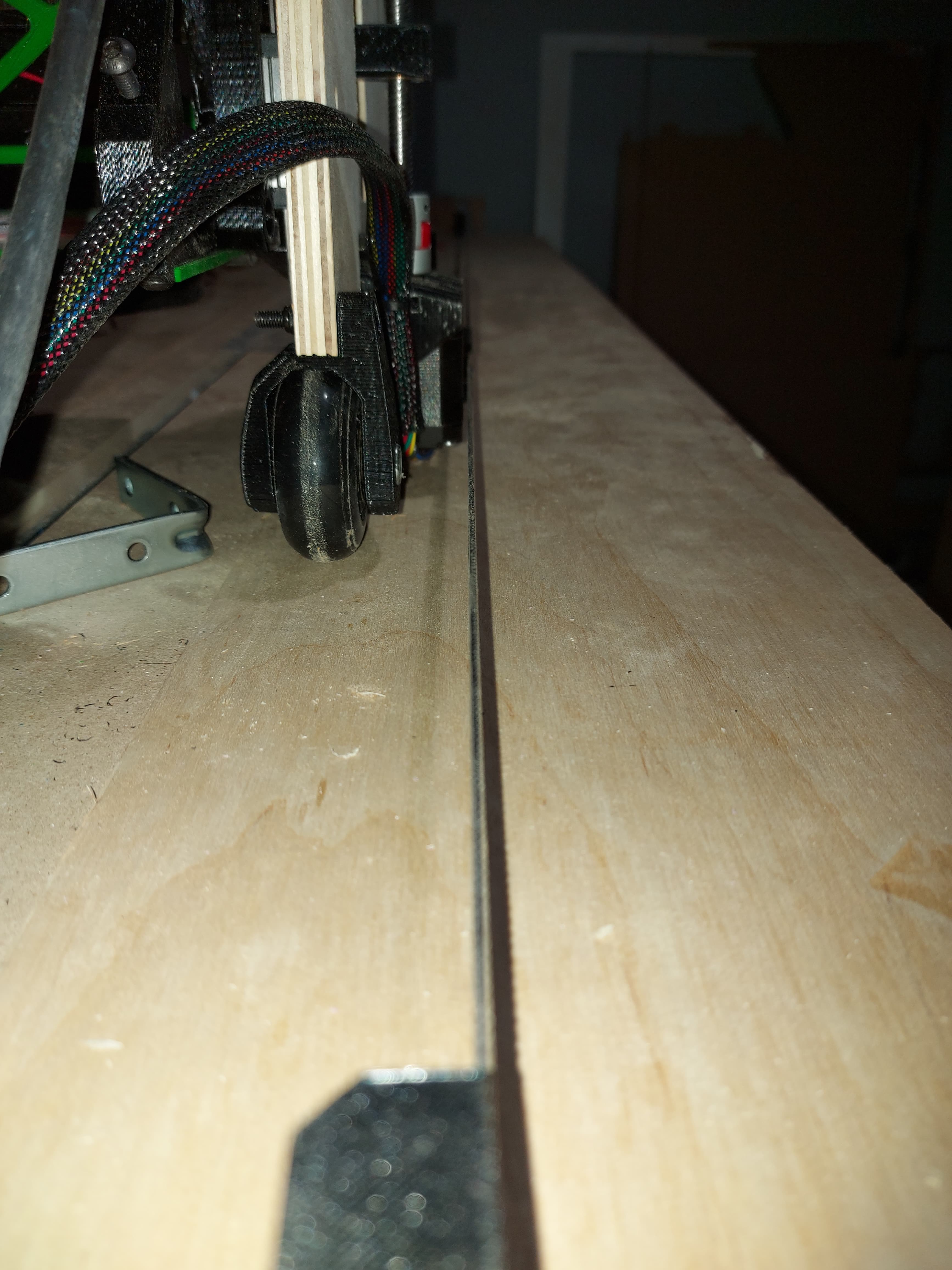
So close!!

Even closer ( video is unlisted )
I’m doing the “almost time to get it dirty” dance!

Dirty dirty…
I eas trying to use painter’s tape and glue stick. 1/10, do not recommend. Fortunately I also put some weight on the work piece. The tape was only annoying.
Not sure why but the front roller wants ro twist off of the track. I think it’s a squaring issue and will maybe resolve itself once the struts are in place.
Lol. Watched the video, I didn’t even realize that I was whistling…