It seems to me that there aren’t appropriate sized 5/16" bolts in the LR2 build for the LR3, but I haven’t looked that closely. The BOM for the 3 calls for 1.5" bolts, and I have some longer and many shorter ones. Well, that size is readily available and inexpensive, so NBD.
I thought there was a couple but you are right, only the 1.75". I found the 1/4" steps are far more expensive than the 1/2" steps in bolts sizes so this was going to either be 1.5" or 2". 1.5" won that battle. The tolerances are pretty close so you do really need 1.5" or 40mm.
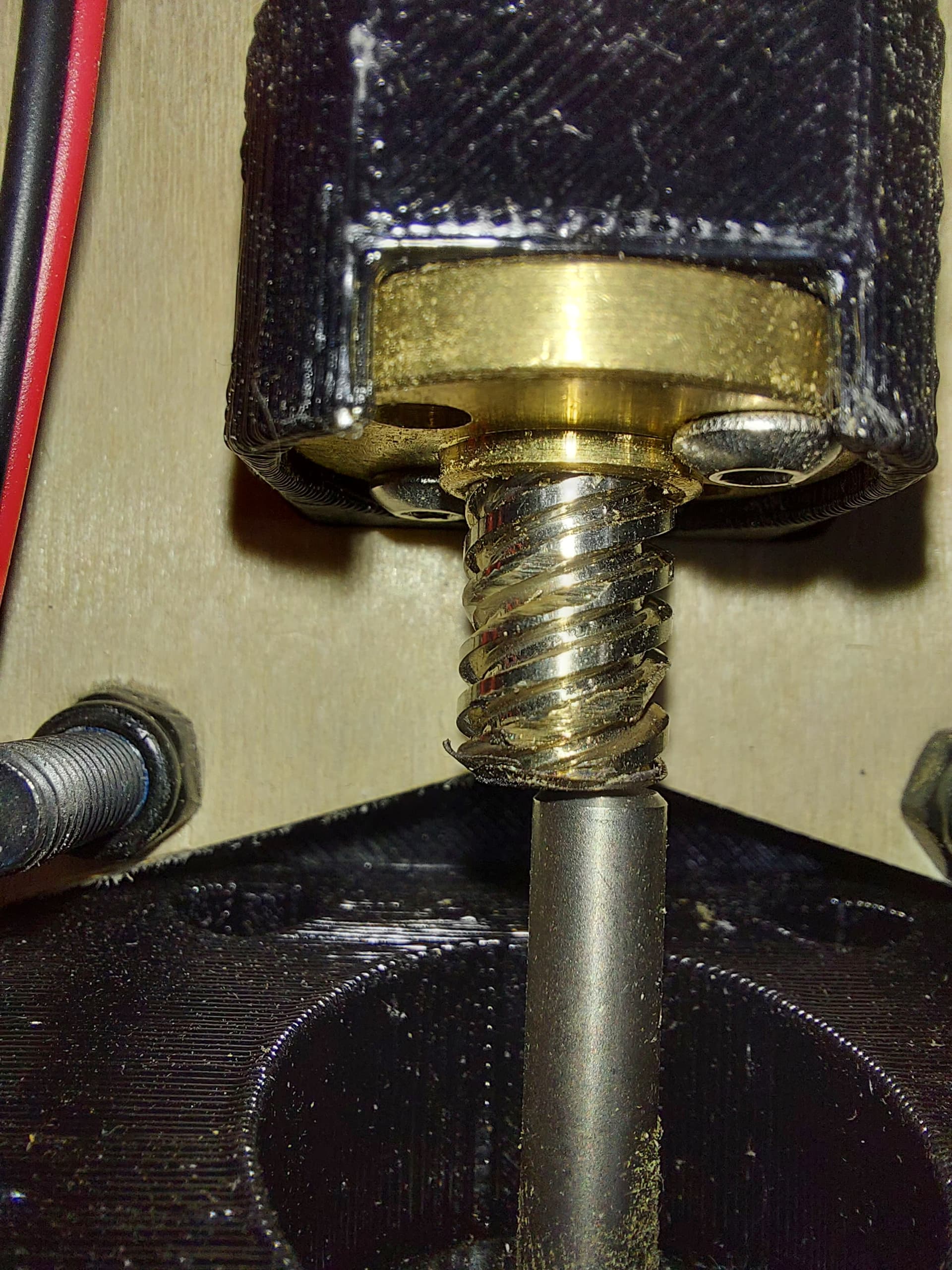
I love it. I hate to tease too much but I bet some people are on full alert for the forum updates now! Such a perfect picture to tease. Upside down, non standard, blurry…nice!
So I got to the bolt supply place, buy they didn’t have stock on the M8 locknuts (Friday) so I got the 5/16" hardware. Of course when I got home, I found a box of 100 5/16" X 1-1/2…
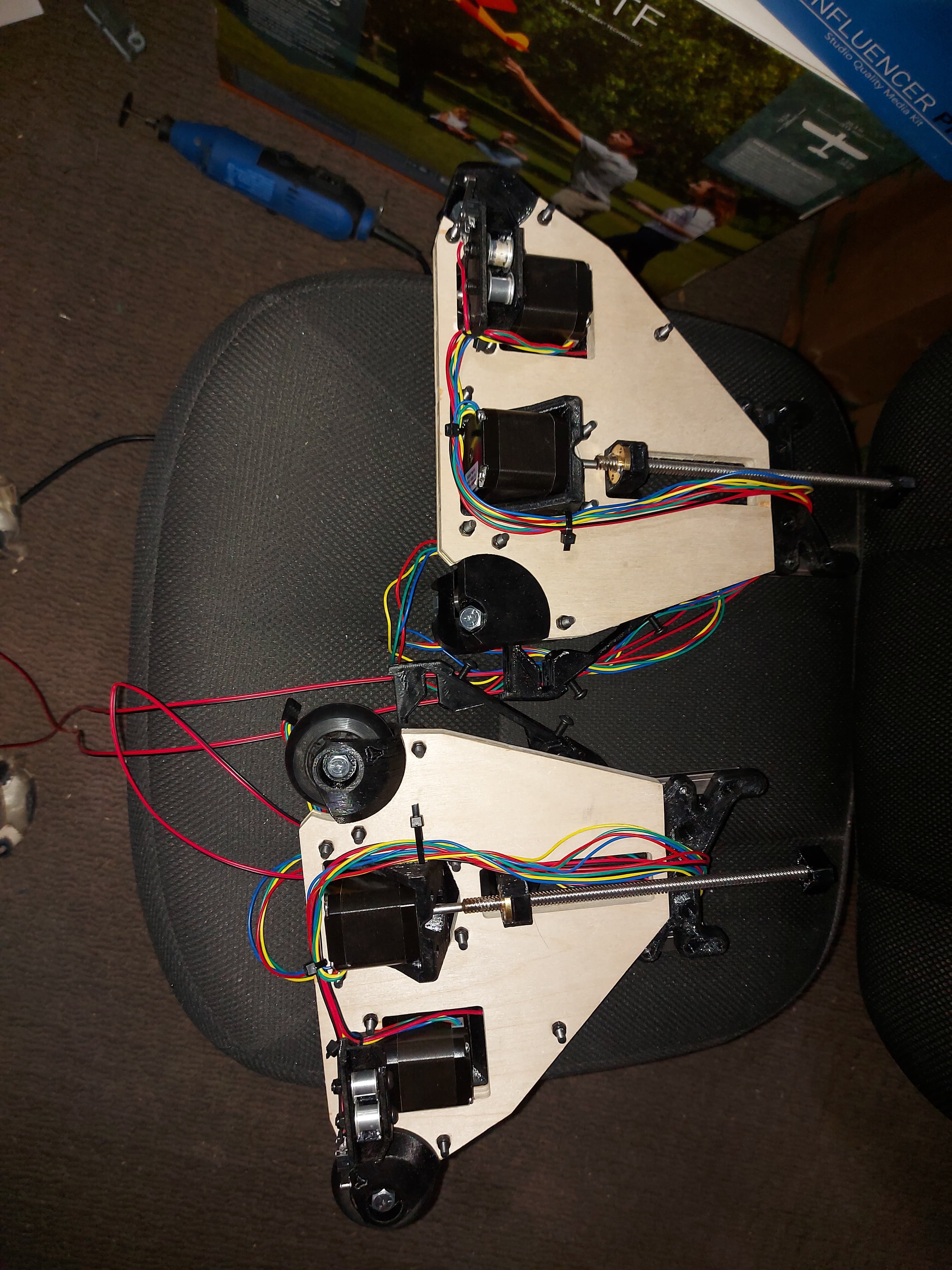
Anyway, I got the bearings into the core, and got the X drive installed. (Sounds like bad sci-fi when I say that…) it’s super hard to thread the belt into the X drive after it’s bolted onto the core. The teardrop opening for the pulley means that the belt gets stuck in the corner when you try to push it through. The Y drives aren’t much easier. I ended up leaving a spare piece of belt in the X drive pulley so that I can pull the actual piece through.
Maybe it will work out when the coupler is on there, but it’s a bit worrying. The Z1 drive is fine.
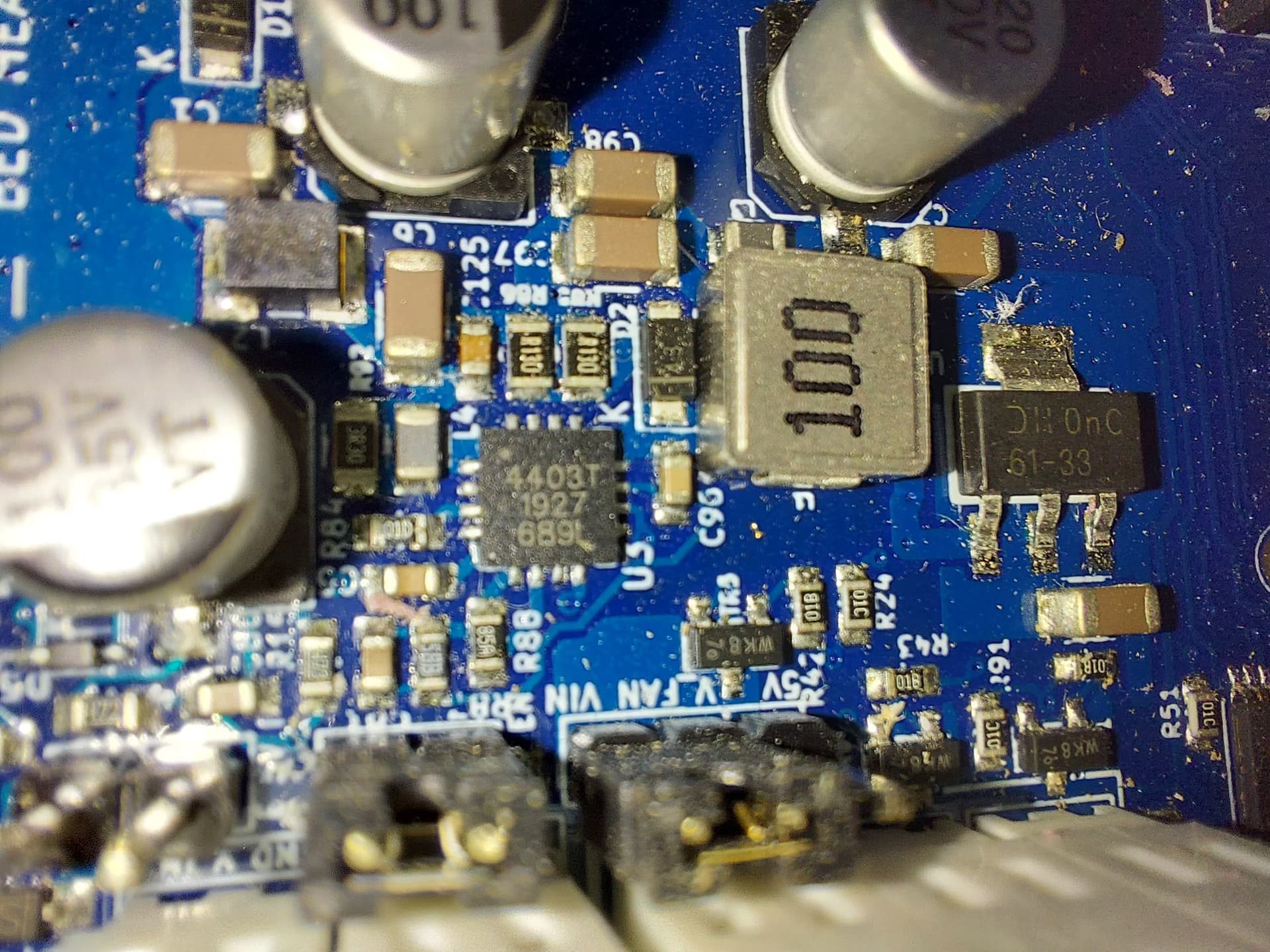
Edit: Oh, the Duet Wifi that I was running the LR2 with died a horrible death in the middle of cutting a LR3 strut plate, but maybe it’s not beyond hope. It seems to respond fine if it’s connected to the computer via USB. The wifi comes on, too, and the web control responds normally. This almost certainly means that it was the 5V regulator that popped, and that it did not take the CPU with it, and the SD card and wifi module also appear to be fine. This is actually quite hopeful for repair chances…
Of course I discovered this after modding the control box for an SKR Pro, and after starting to print it. Oh well.
I had a duet kill its wifi card. I replaced it with a wired version, and experimented with the dead one. Desoldered the bad wifi module and added pin headers and a new wifi module.
It’s surrounded by close-packed sypport components, making the liklihood of me being able to replace it very low.
The actual chip isn’t in stick anywhere
Looks like Im not going to be able to repair this, but the good news is that I can just supply 5V to the bus via an external 5V supply pin, or via the USB port. This does limit 5V current available, but should be adequate. It is a hassle to fo though
That is a tough one. I recently saw a post (on hackaday, maybe?) Where they bent a perfectly sized wire to touch all the pins at once and then heated that wire with the soldering iron to release a chip like that.
It won’t matter if you can’t get a replacement though.
All I’ve really verified so far is that there’s no voltage on the 5V (And thus also the 3V3) rail. This is the most likely point of failure for that.
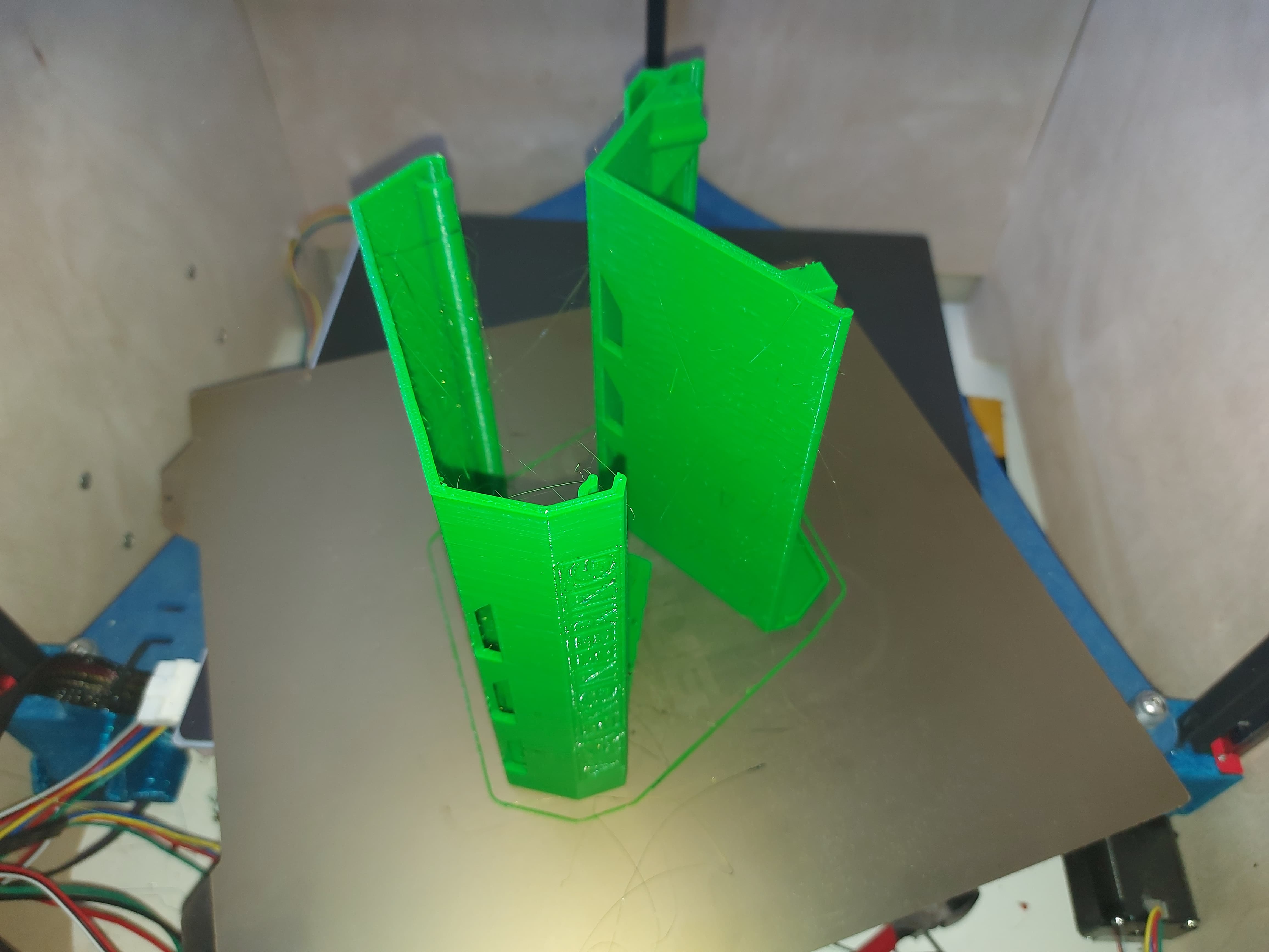
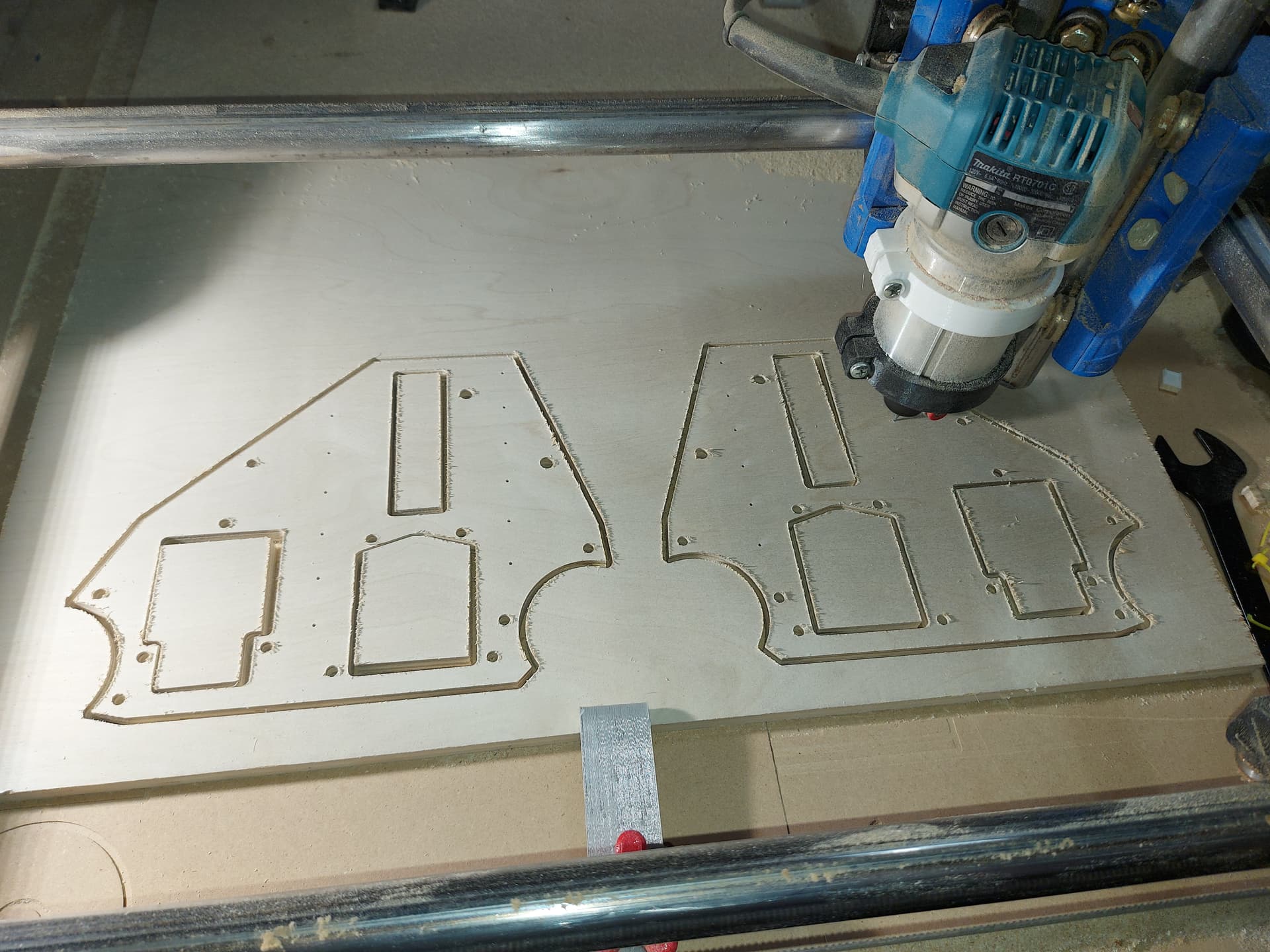
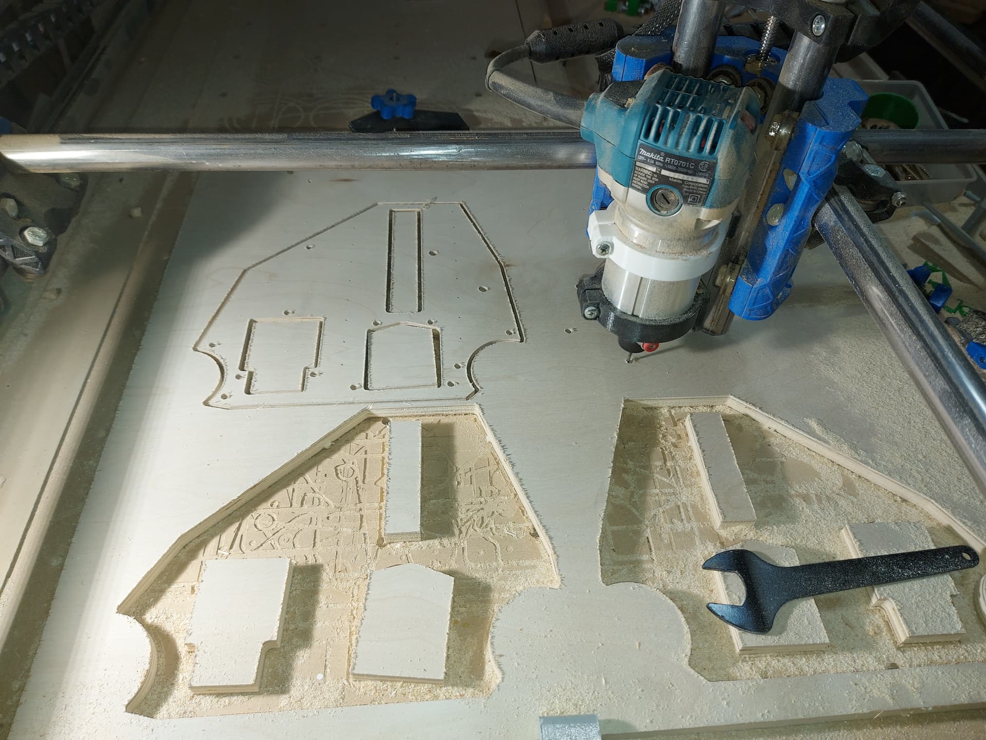
I think this may be one of the largest area prints that I’ve attempted so far. The smooth PEI surface still has some non-stick parts to it, it seems, I had some trouble with the first layer, some of the corner hole perimeters didn’t stick, but it looks like it will be functional enough. I figure that the green is appropriate for today.
So when I finished those temp plates, I went to pull the green filament out… and there wasn’t any. Those finishrd printing with the dribble from yhe nozzle, but they did entirely finish.
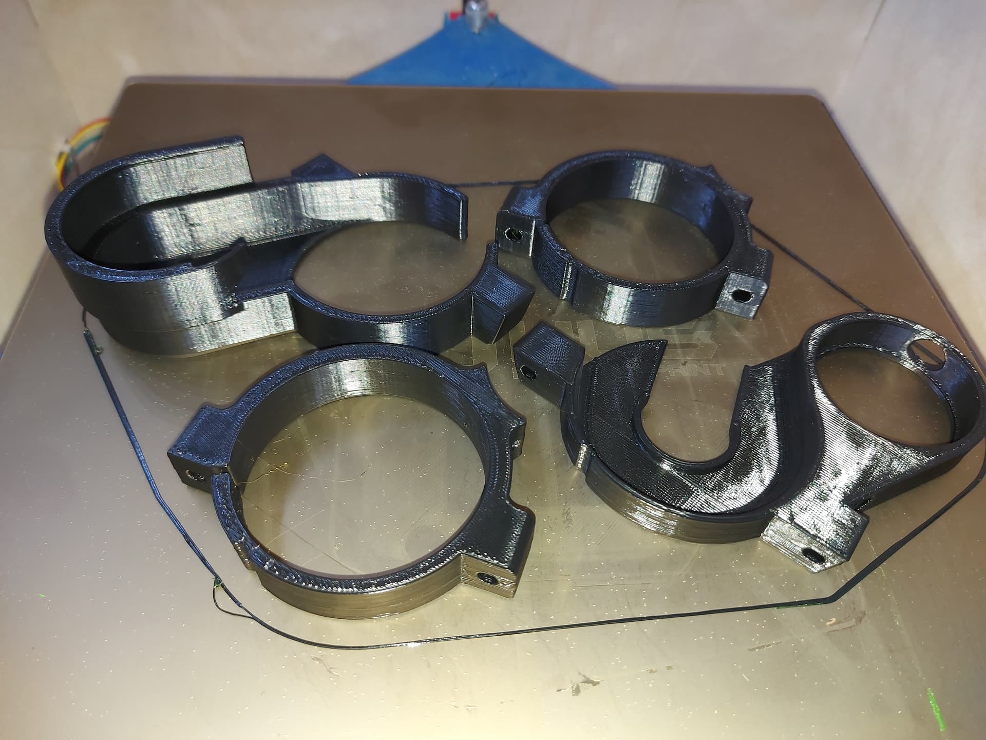
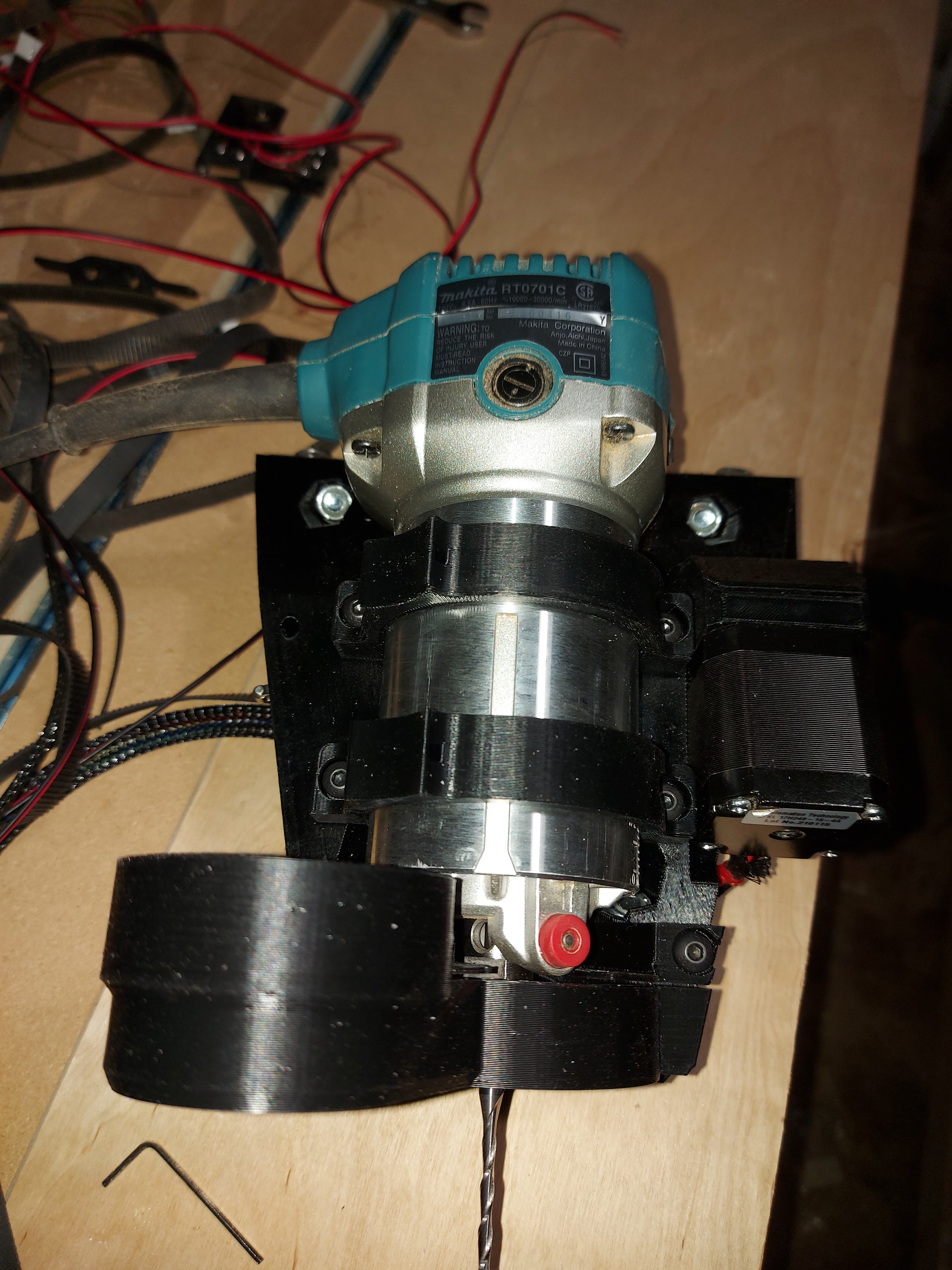
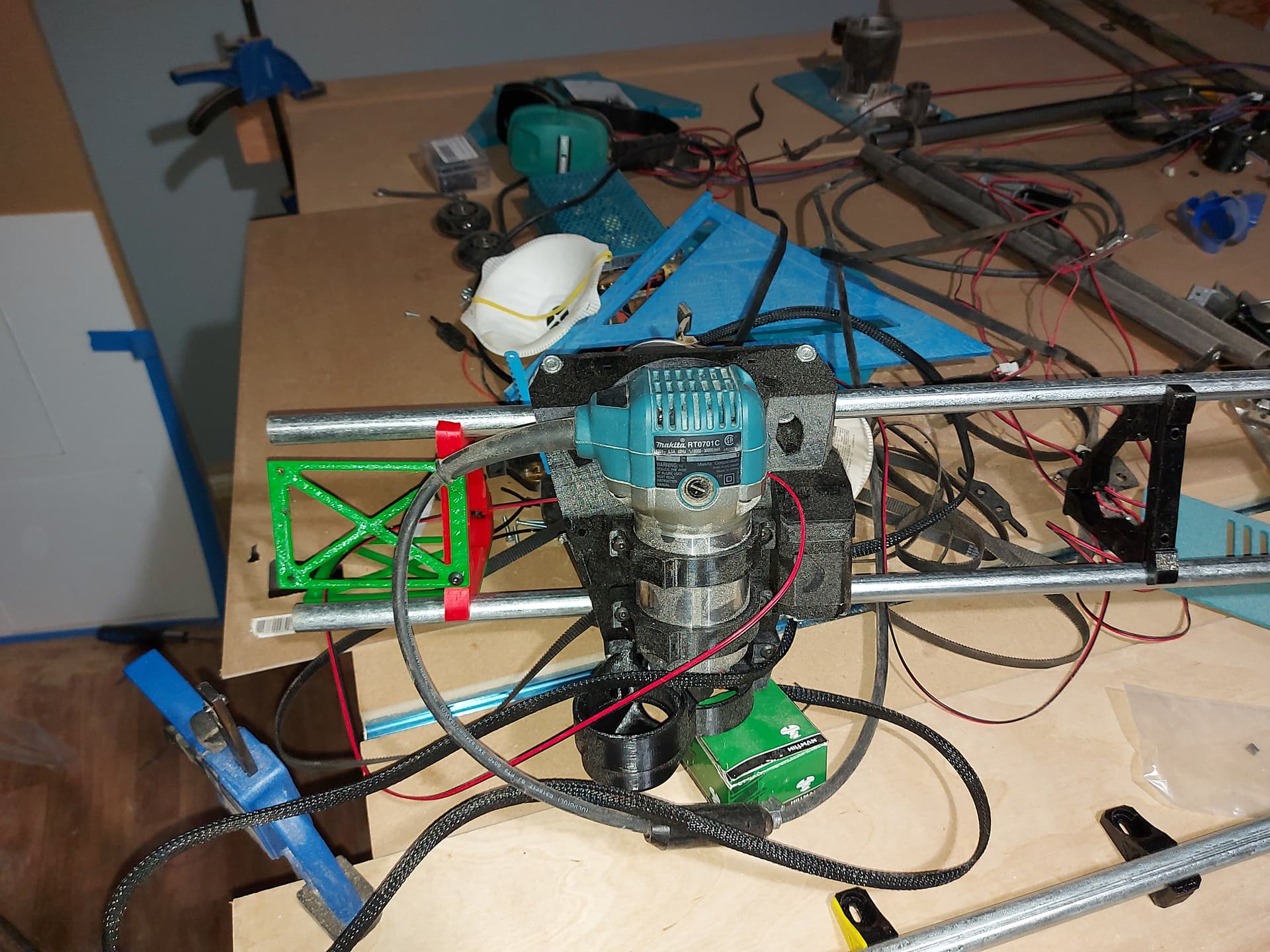
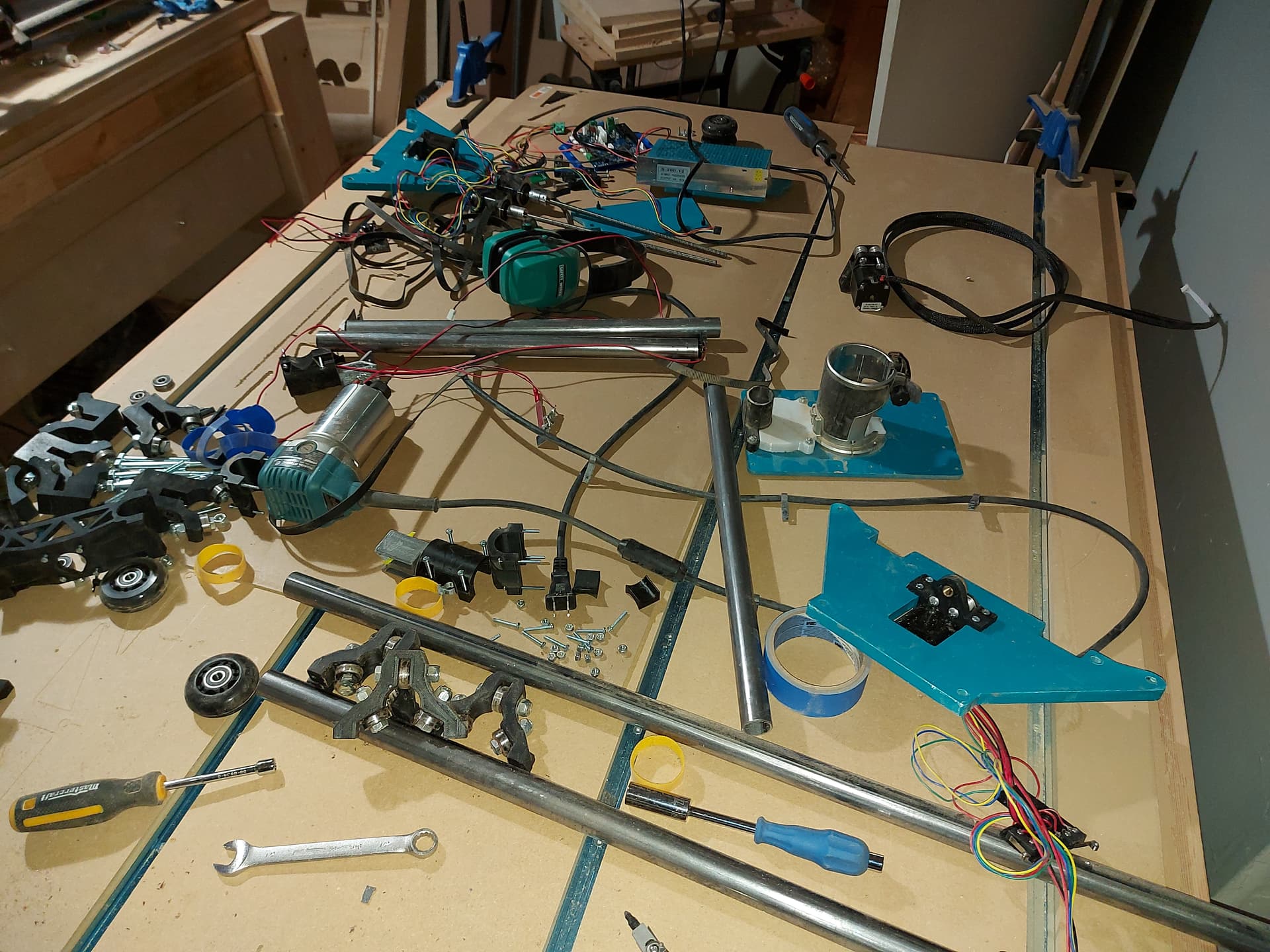
Test fit of the Makita and vac parts. So far so good.
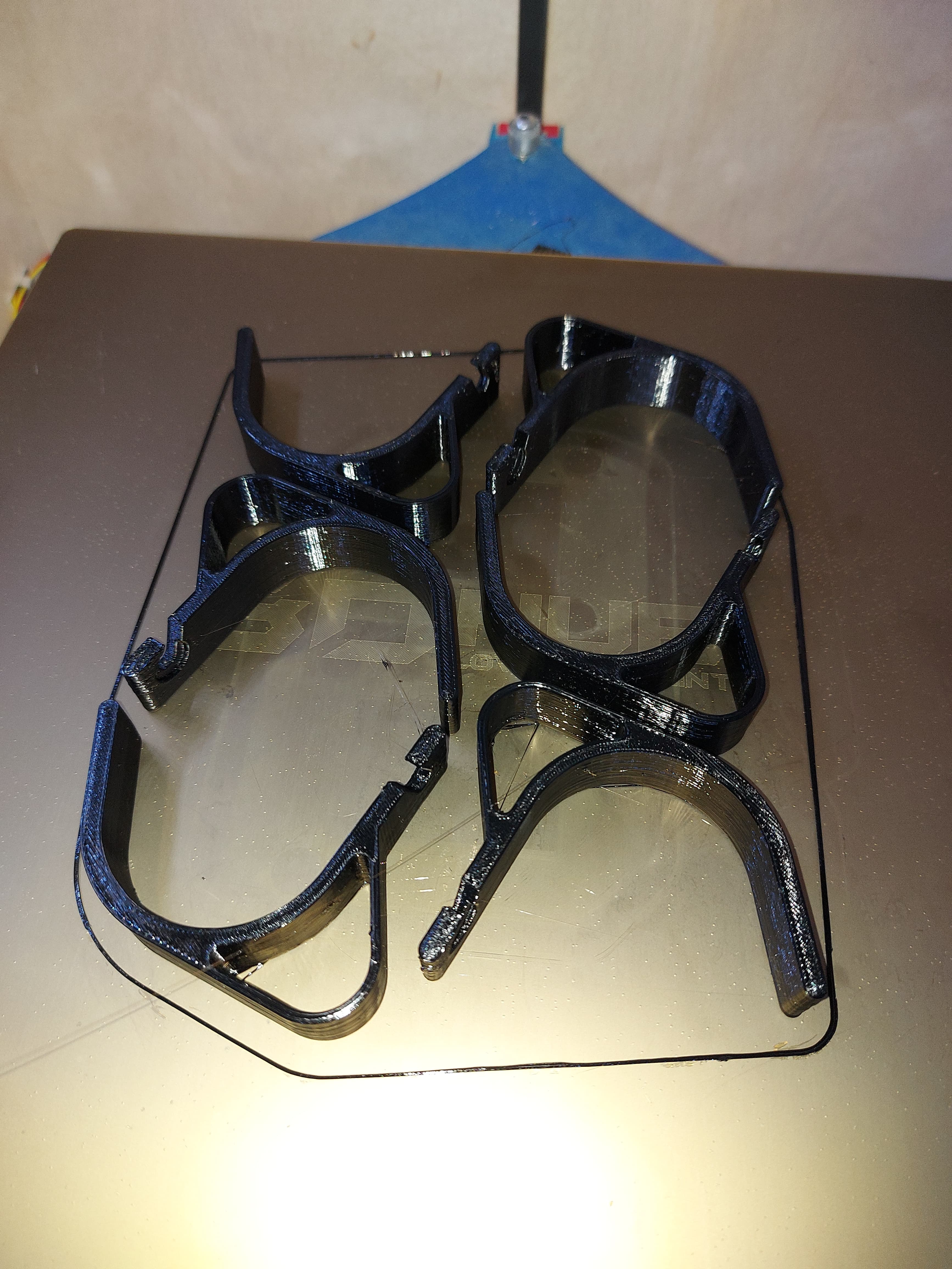
I already fit the skate bearings i to the core, I’ll need to pull a couple in order to fit the nuts for the vac parts. I’ll see if I can squeeze them in past the bearings first
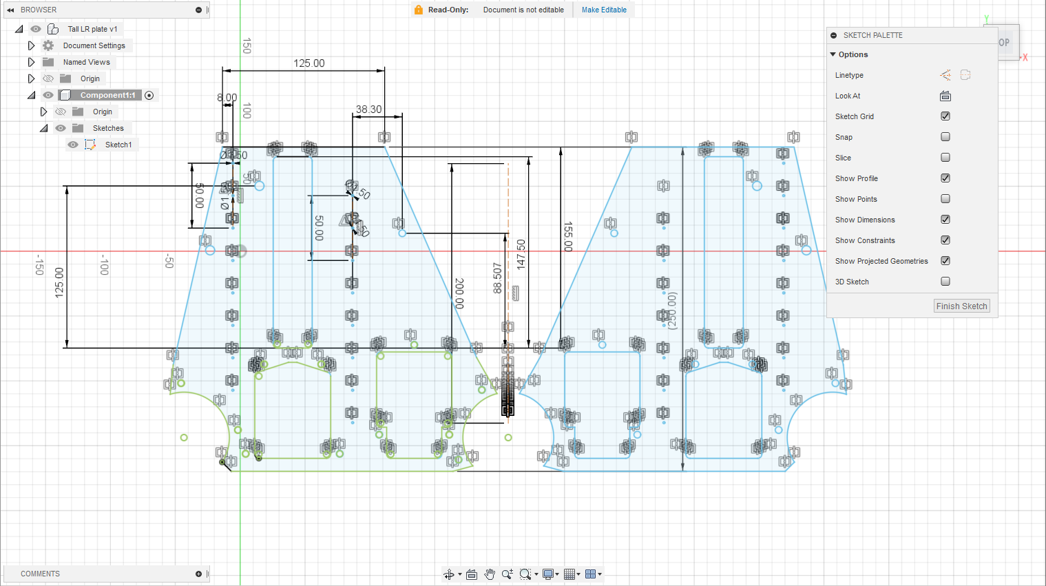
I think that I understand what went wrong with my YZ plates. When I flipped the tool paths for the second plate, EstlCAM didn’t reset the zero quite where it did before. It appears to be off by the difference between the tool diameters. I think this is because I had the 1/8" tool defined when I flipped the holes and cutouts, and the 1/16" tool defined when I flipped the pilot holes for the rails.
I’ve re-done all of the CAM by mirroring the .DXF file instead, and re-working it, instead of flipping tool paths.
I also had some fun with the .DXF file in the “200mm Z rails” department.
Still super rough. I just stretched the opening for the Z screw by 50mm, lifted the Z stop hole by the same 50mm, added 4 more 1.5mm pilot holes, and then distorted the top geometry… I don’t like that so much though because it stuffs up the Z stops, so I’ll keep playing with the idea.
I don’t think that I’ll need more Z travel, really though, so I’ll cut new plates using the supplied drawing first. With the idea that the LowRider is at its most stable and rigid at as low a position as possible, the extra height is probably counterproductive, but I’ve got some ambitions of carving foam airplanes which might need some more height… Unless I laminate the foam, which is also an idea.
Sweet this could be cool. I am probably going to try and make the dual bearing plate anyway so if I do, all you will need to do is swap the printed parts!
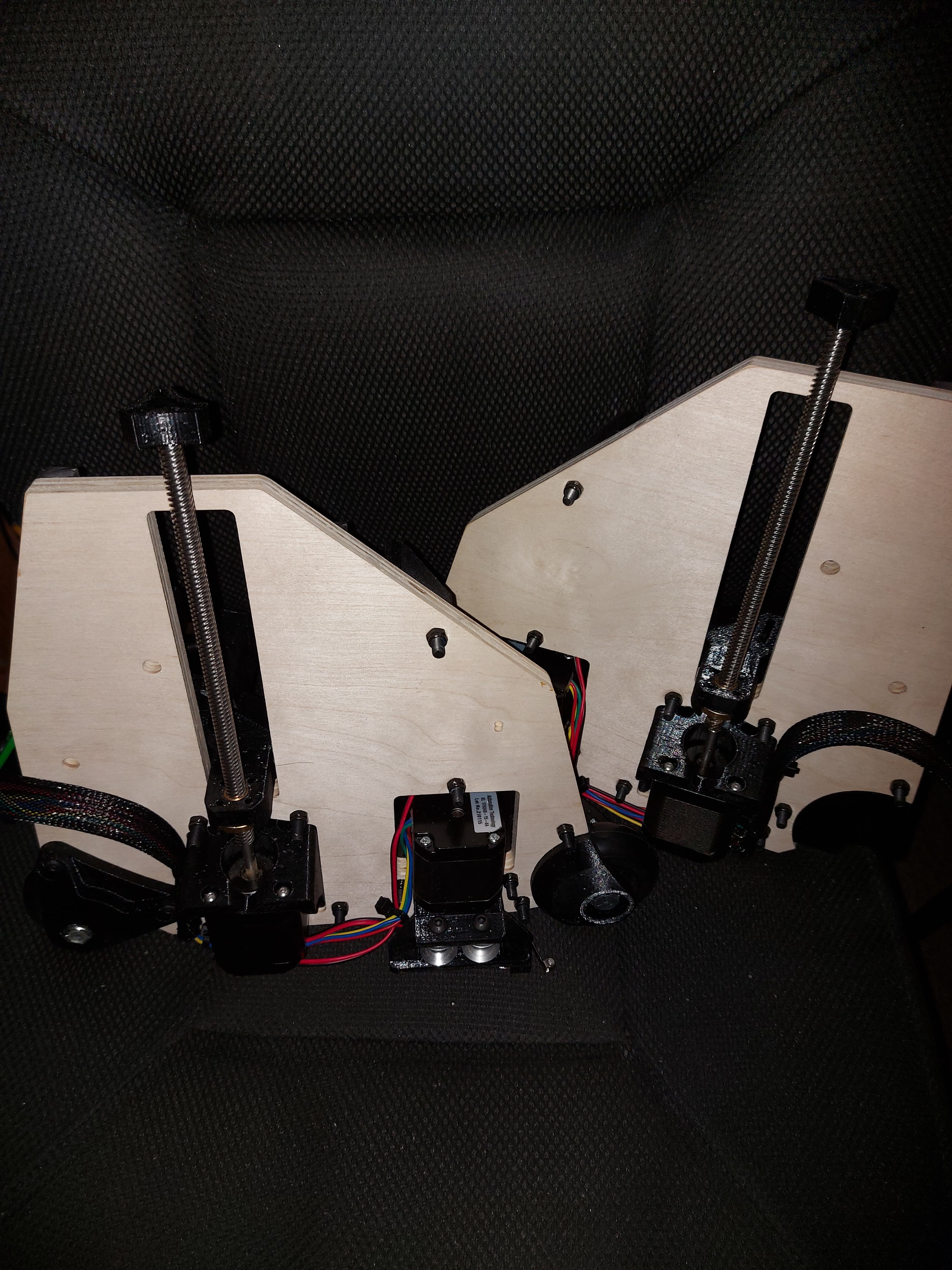
I also get to see what is looks like with 200mm rails!
I decided to go with the “offroad” version with the jacked up suspension. I may never use that extra 50mm of Z, but I’ve got it, and all it costs is a little extra homing time for the Z axis. Maybe a little mass.
I had about 3 ways to stretch the plates in mind. I wanted to preserve the angle for the Z stop, and for the front toe, where it blends into the wheel and roller so well, but it didn’t work to keep it, only at the other side, so that one isn’t as seamless. I found that keeping that toe angle meant that I couldn’t raise the Z stop appropriately. The other way that I was thinking would be to add 50mm vertical lines in between the vertices. But that looked kind of lame, definitely a hack job. It might have worked for the one side, but this is what I ended up with.
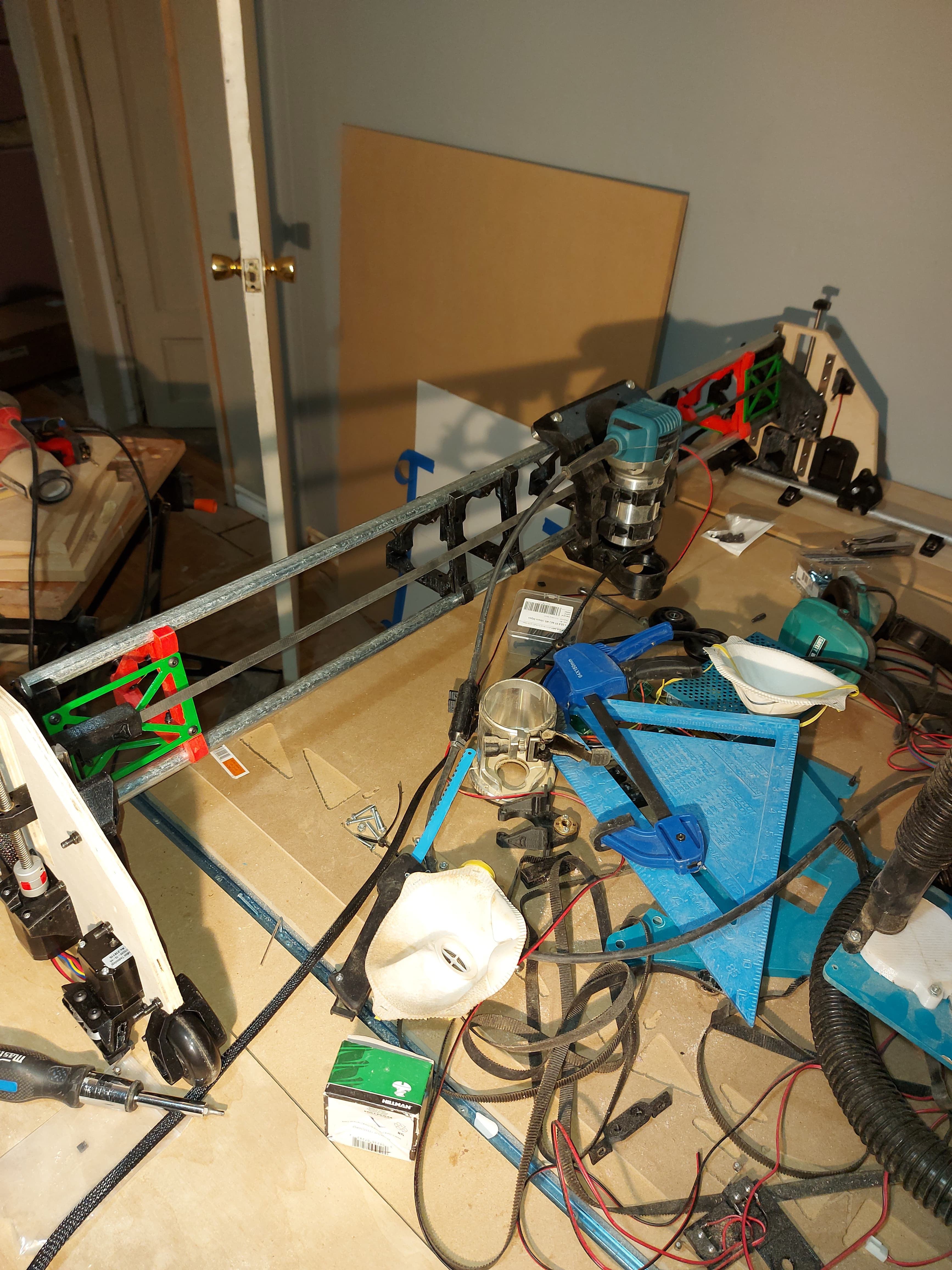
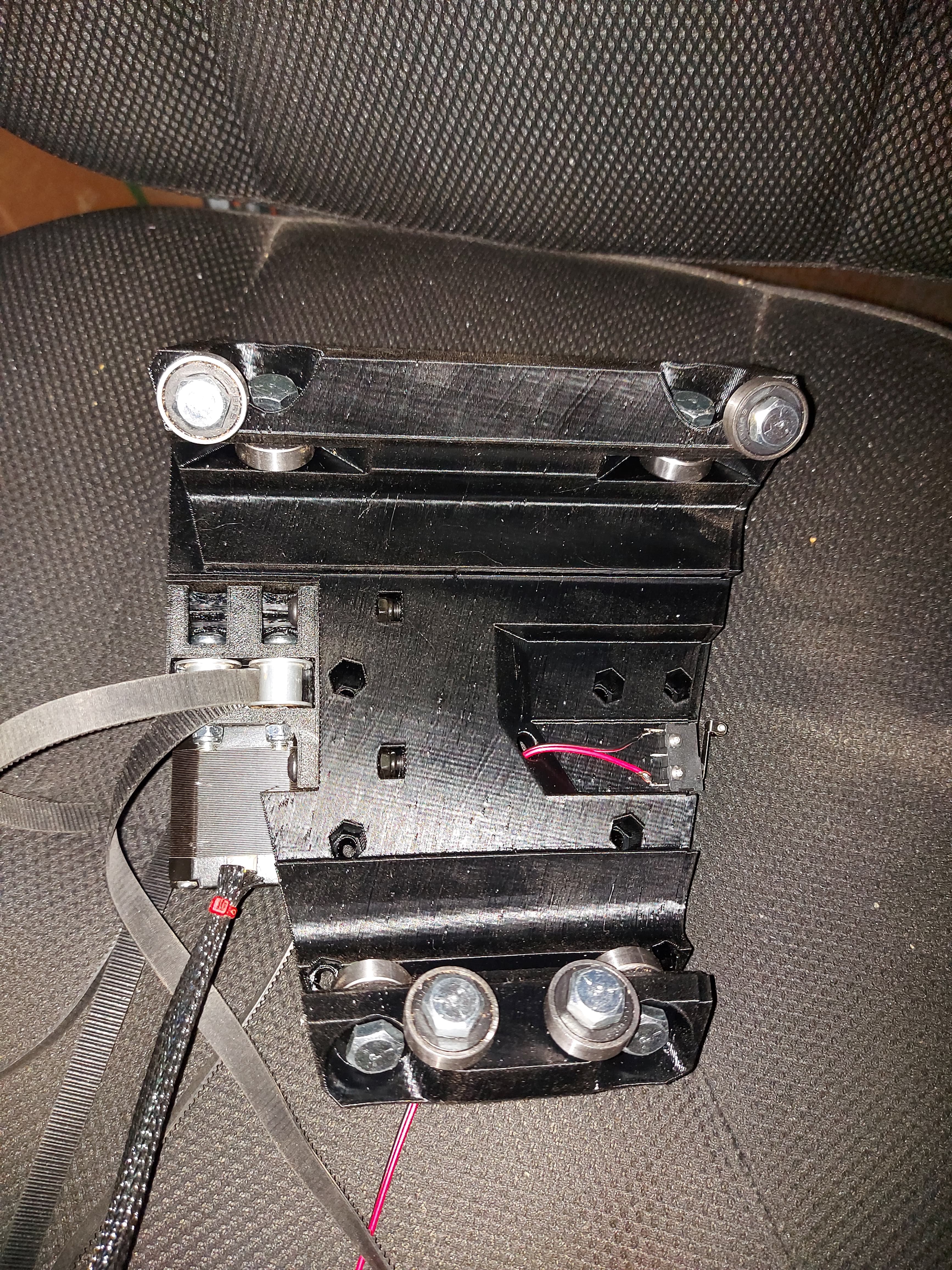
Started processing the gantry assembly. I decided to put the temporary braces on 2 surfaces at each end. With it relatively loose, the core has a bit of room, so with a little move tension, it ought to be good.
I’ll need to see what the process of bolting it to the end pieces does, and then I should be able to get things in place for a test run.
I still need to gather up all of the LR2 printed parts and rebox them too.
The table is still a mess, but 18" wider now. The iveralm width of the table is 63" now. Should be able to load 4’ material, but the beam span of the LR3 will be 47.5" because that’s what I can cut fot a strut plate.
I found that I had another Z alignment problem. The screws holding the XZ plate to the linear rails werent tight enough, so there was a mismatch in the depth from the inside of the YZ plate. This caused the axis to bind up near Z min, but a little torque on the screws sorted that out.
Found another little “gotcha” in thst you need to remove the rear rail rider in order to install the bottom strut plate, even a temporary one.
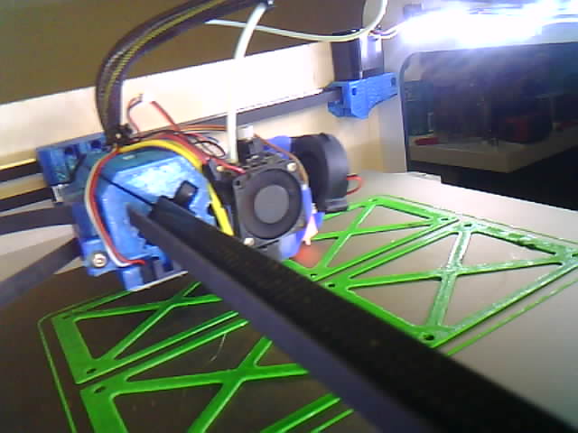
Also, my X belt tensioner is cracked, so I need to print a new one. I’ll get that started, then I have some work to do before I hit the hay.
 A sad day.
 Oh well.