Yes. If I’m not mistaken the UART1 section is for the TMC2209 Drivers
1 Like
Yes, leave it as is.
1 Like
I think when the new JP3 shows up if I’m having issues with the Fluiddial again I’m gonna use my “phone a friend” card
and ask one of you for help. Before frying another Jackpot board
3 Likes
Are you getting jackpot errors with a fresh firmware install and fresh config without the pendant hooked up? Just wondering what actually fried your original JP3
Before I fried it…
It was working fine. out of the box (V1 Installed version 3.9.9 FluidNC and v1 Installed Config files)
….The Only exception was the Fluid dial not working or in the state of Not Connected (NC)
I did switch from AP mode to Client Mode for WIFI I prefer that method and configuring a Static IP address for the Jackpot so I can upload files from my workstation in the office.
Technically I can still see the files on the jackpot and the SD card and Flash it etc. but It’s in this perpetual Reset mode and will not function as it is intended.
I think when I connected the external Barts RJ11 module to the JP3 module pins I must have sent 5v to the 3.3v ESP module. or something like that
I do the same. It works well if you have good wifi in the area of your machine for sure!
I wouldn’t think that would be possible. Using his board in that extension header should have been good to go, not needed on the JP3, but still should not have fried the board. Any chance you plugged it in 1 pin to the side or anything? Not sure if that would have hurt anything or not, but seems more plausible than if it was hooked up correctly. Sure would be good to understand what happened so we can help others not have the same situation is all I am thinking.
2 Likes
Well, as usual, I rushed into it and did not document the steps I took or take care to double- or triple-check before hitting the ON switch.
I did this before with a Jackpot 1 board …You would think I’d learn from past mistakes, but I’ve always been a shoot first and ask questions later kind of tinkerer.
1 Like
What is your wiring order?
I have a Fluid Dial, but I haven’t used it since making the CYD pendant. The wiring order for the dial should be:
- GND
- VMOT
- null
- TX
- RX
The order is different on the JP3 expansion.
Maybe this will work:
uart2:
  txd_pin: gpio.14
  rxd_pin: gpio.13
  rts_pin: NO_PIN
  cts_pin: NO_PIN
  baud: 1000000
  mode: 8N1

Is this what you had on the JP1 config?
1 Like
I get it 100% I can very much be the same way. Good for you coming here after the fact and being able to say what all you did. Kudos for that!
1 Like
Yes this is what I had on the JP1 with Rj11 module from Bart in the expansion pins of the JP1 and it was working on the JP1
Hopefully that will work on the JP3 expansion too then.
![]()
If your previous board was a jackpot1, could you just replace the esp plug module on the board? That is like a $10 fix vs a new board. I think im local and have one… Dm me.
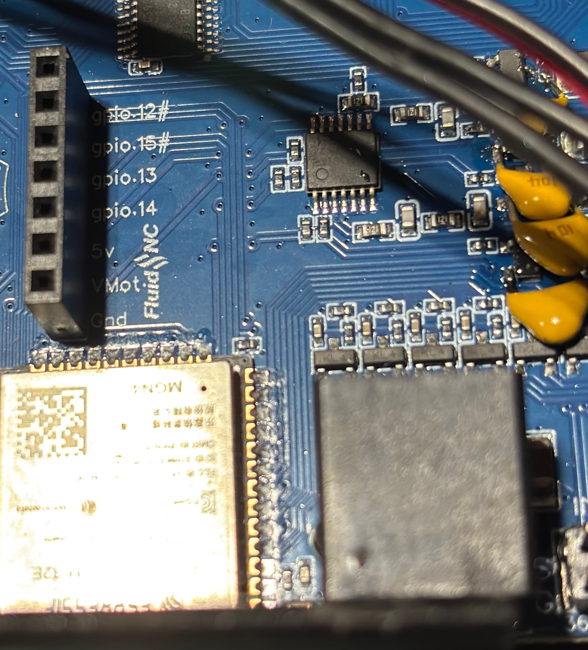
well my preference would be to get the fluid dial working on the onboard rj11 of the JP3 so I could use the 0-10v spindle module on the JP3 expansion pins.
From what you are saying if I just uncomment the ##Pendant section of the config file then using gpio 12 and 15 with the rj11 on board should work with the Fluid Dial as it is currently wired.
Thats the Hope at least. I may just copy and paste the uart2 text and put it below the uart1 text and leave the ##Pendant section alone…since that caused issues before. and use the text as Britt has posted above:
https://us2.dh-cdn.net/uploads/db5587/original/3X/2/0/20449851b0119fab293e7825fc2a76cc705b3311.png
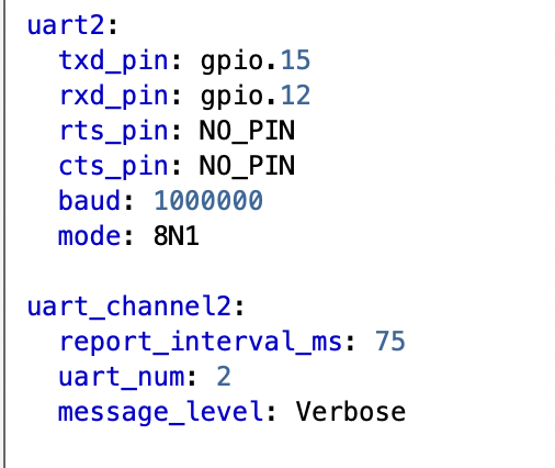
1 Like
If all else fails, I’ll just use the JP1 board from the Primo and reconfigure it for the LR4.
I’ve already ordered a new JP3, so it’s a $90 lesson to cool my jets and double-check things before hitting the SEND button…
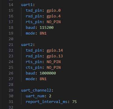
I am using the RJ12 plugin with my CYD pendant.
Here is the uart 1 and uart 2 section from my config:
uart1:
  txd_pin: gpio.16
  rxd_pin: gpio.4
  rts_pin: NO_PIN
  baud: 115200
  mode: 8N1

uart2:
  txd_pin: gpio.15
  rxd_pin: gpio.12
  rts_pin: NO_PIN
  cts_pin: NO_PIN
  baud: 1000000
  mode: 8N1

uart_channel2:
  report_interval_ms: 75
  uart_num: 2
2 Likes
Sorry on the loss. If only we knew someone who could resolder those modules…
1 Like
I di plug in my CYD pendant to the JP3 before I fried it and had the same results as the M5 Dial.
But memory is fading and I can’t remember if it was before or after changing the config file.
The most likely thing is that I somehow made a mistake when un-commenting the ##pendant section of the config file and just did not catch it. IE: an extra space or mistyping.
Anyway now that the JP3 is properly fried. It literally gets super hot to the touch just below the ESP module even just plugged into the USB 5v port. Hot enough that you pull your finger away from it right when you touch it. Which also makes me believe I must have done something ill-advised to it.
2 Likes
The extra spaces shouldn’t have caused any damage. It would say NC on the display, but it shouldn’t hurt anything. It doesn’t make any sense.
Maybe some one else has a suggestion for you to try measuring some points on the board.
1 Like
I’m going to ask questions so I can understand. And maybe help others not repeat.
What was flashing, exactly?
I have a pair of M5 Stack FluidDial pendants that I can swap back and forth between Jackpot V1 (with Bart’s FluidNC expansion module) and the Jackpot V3. So yes, it’s known to work.
Yes.
Correct. We followed the standard.
Please do!
There was something wrong inside the pendant with the wiring there. Bart’s modules are known to work.
It’s possible if you flip/flop the premade cables in Bart’s kit. At least I think it’s possible.
That blown Jackpot would be interesting to analyze for root cause/failure impacts.
If I remember correctly, here was the sequence of events.
-
no power connected (either 24v VMOT in or USB)
-
I connected the RJ11 expansion module, getting the orientation correct so that the vmot, ground, 5v, and gpio pins were alligned correctly between the expansion module and the JP3 pins
-
Powered on using the 24V Line in power
-
The green LED light on the JP3 “briefly” came on (and so did the LED strip I have connected to the same 24v line
-
Then the green LED flickered and went off (so did the LED strip), and then both attempted to come back on, like when the power to your house goes out but then comes back on right away
-
I thought this was odd, so I shut the switch off and disconnected the Bart RJ11 module.
-
Note: I’m not sure if I left the Fluid Dial RJ-11 connector in the JP3 RJ-11 or if I moved it to the Expansion Module. <<< I remember thinking that since the JP3 RJ-11 and the Expansion pins “share gpio 12 and gpio 15 that I must have shorted something out because the Bart RJ-11 Expansion module does have pins for all of the slots, including gpio 12 and gpio 15 so in my brain I had something connected to the gpio 12 and 15 pins in both locations (RJ-11 on JP3 and Expansion module pins)
So that would be something easy for a “tester” to check what happens if you have an RJ-11 plug in the JP3 RJ-11 port and “ALSO” connect a Bart RJ-11 module to the JP3 expansion pins and turn on the power.
^^^ I’m the reason we can’t have nice things^^^