thank you
4 Likes
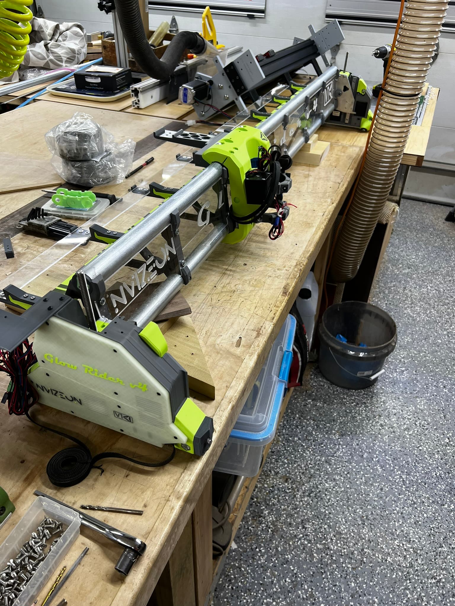
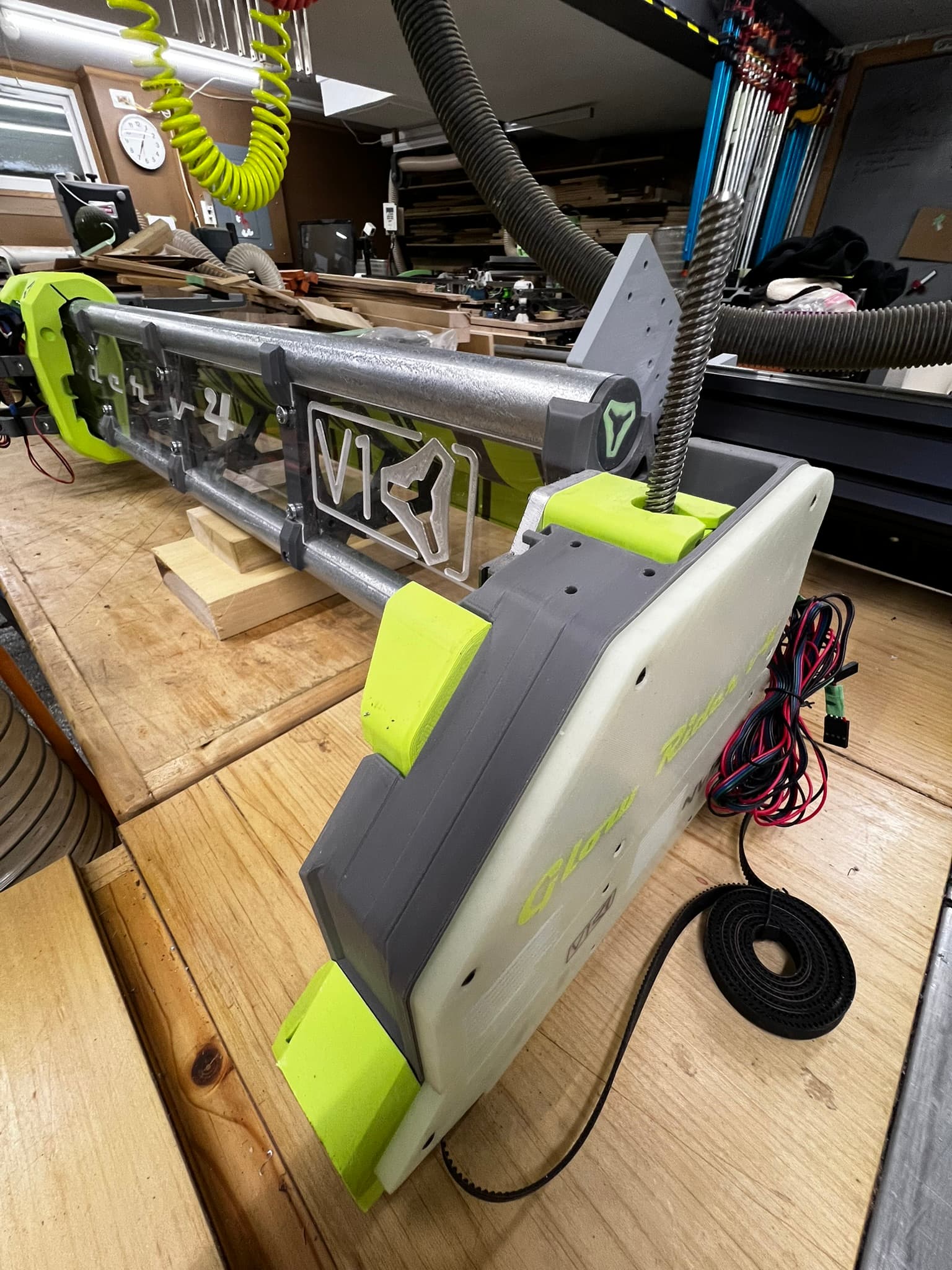
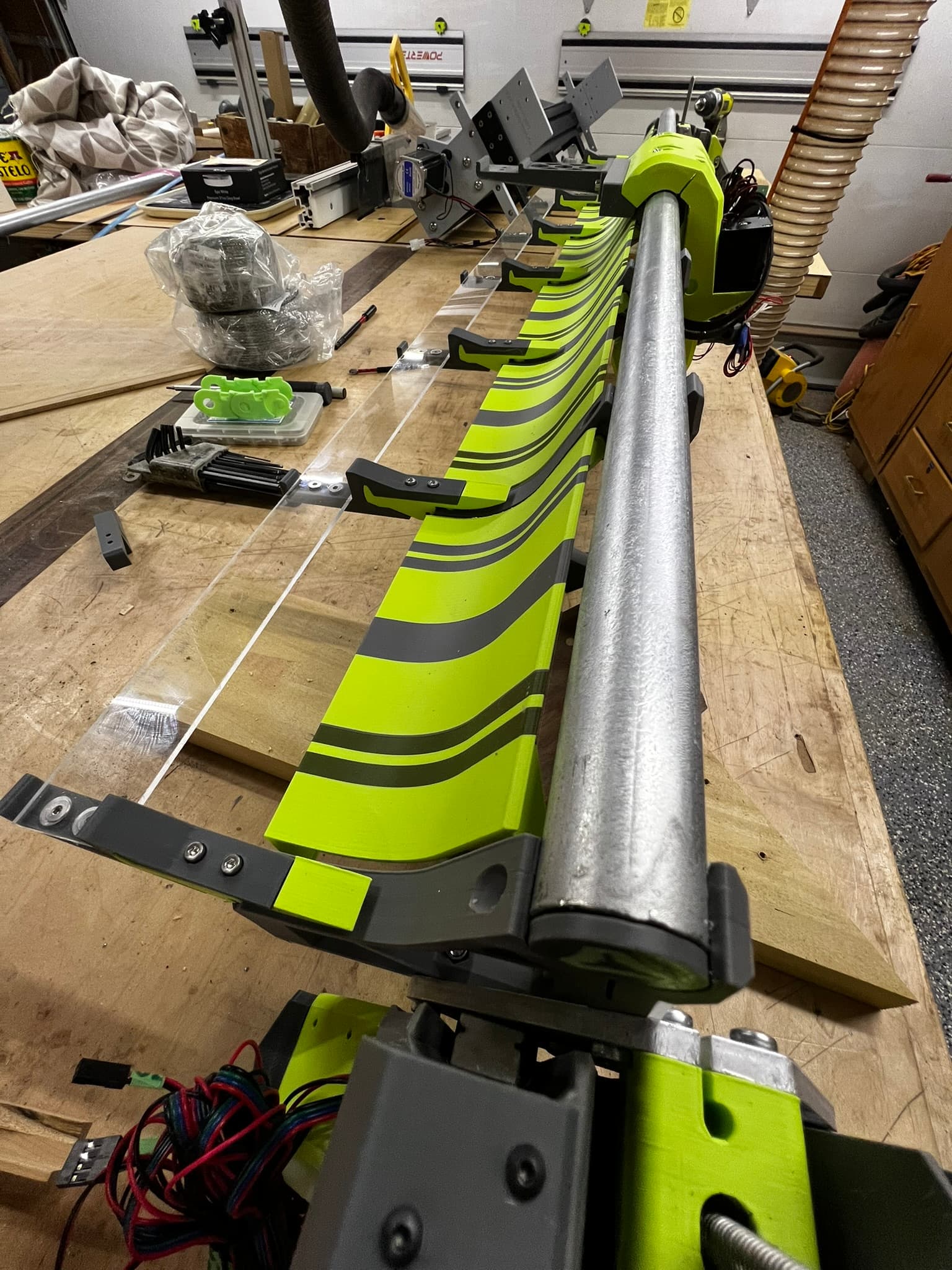
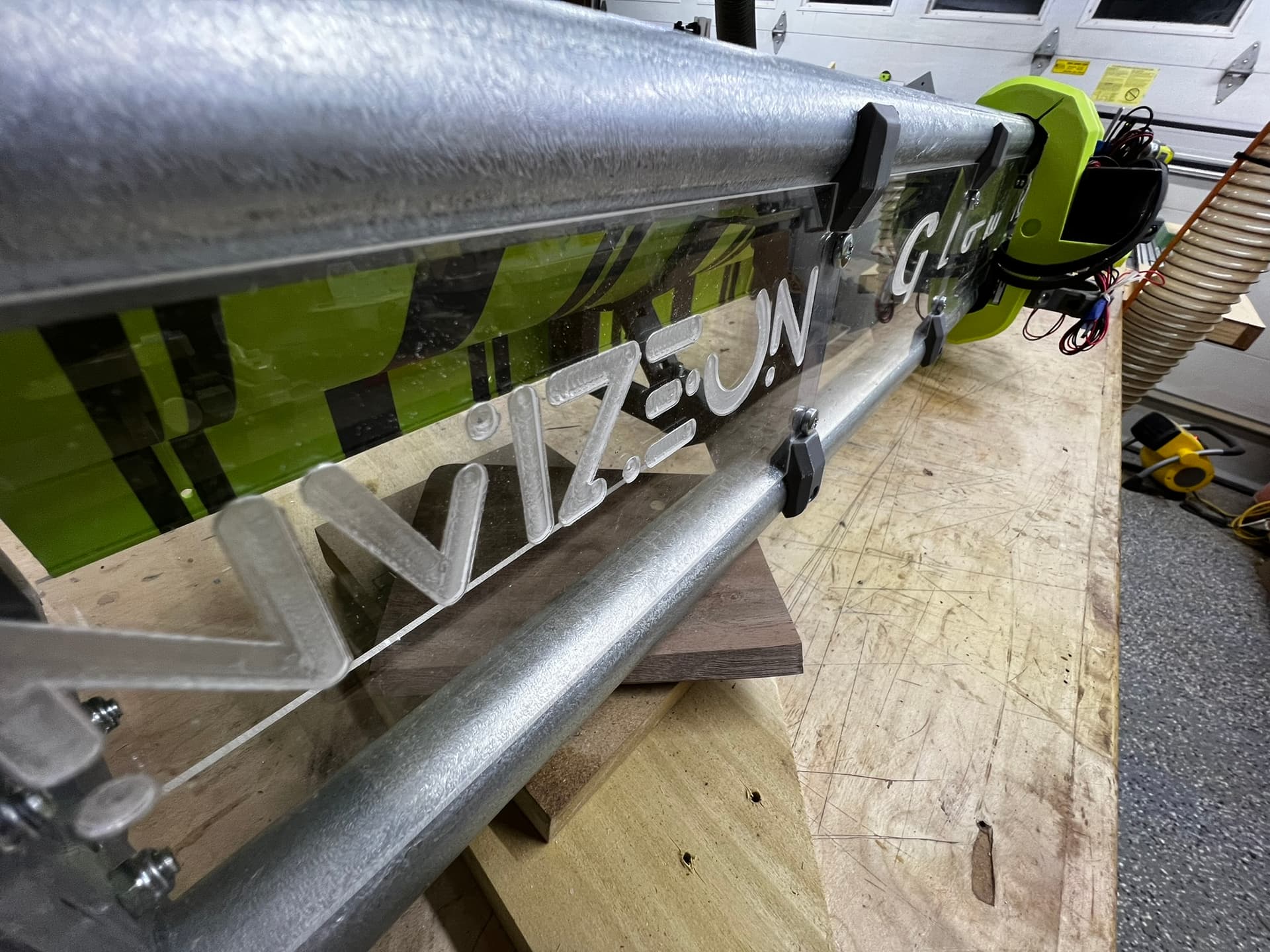
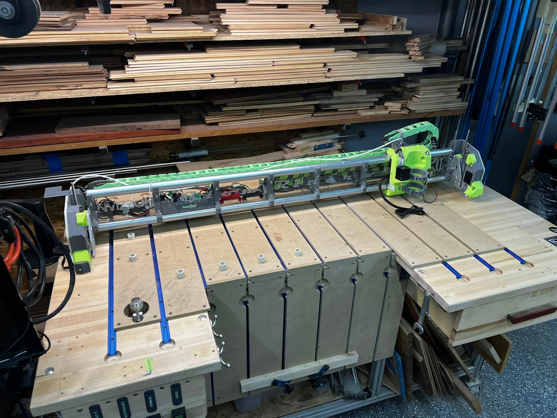
I’m beaming with joy at my progress so far on the Glow Rider V4 ![]()
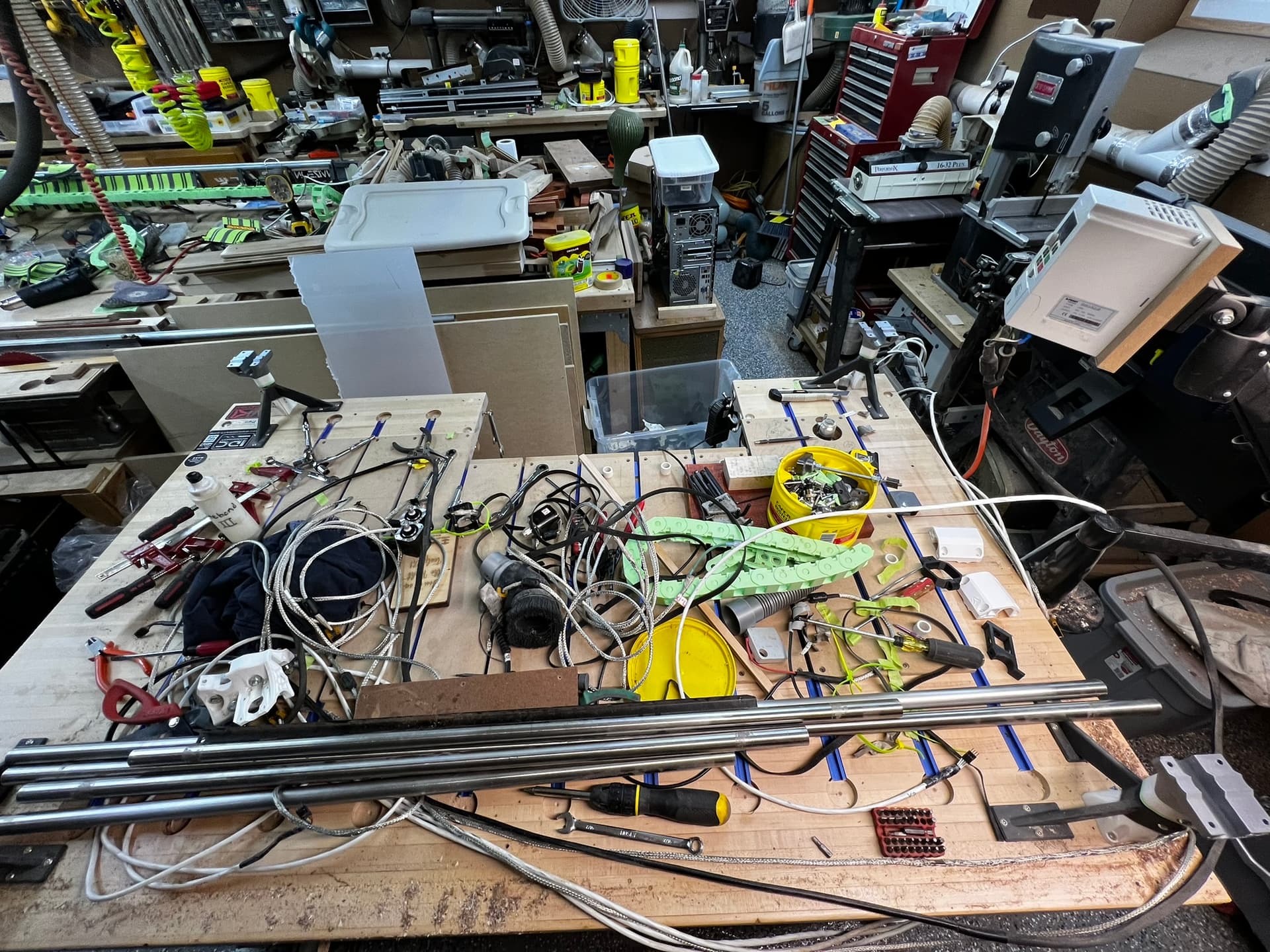
The next step will be bittersweet…I need to disassemble the MPCNC Primo.
It’s been a great machine for over a year now, but the LRv4 will be a more reliable and robust machine.
8 Likes
That looks great!! I think you’ll really like the easier workpiece load and unload with the lowrider as well.
1 Like
I agree and the ability to reach the “back” of the spoil-board without awkwardly reaching over the front “X” rail.
Well, as the saying goes: “Dis-assembly is the reverse of Assembly.”
The Primo served me well, but now it’s time for its successor to take the reins!
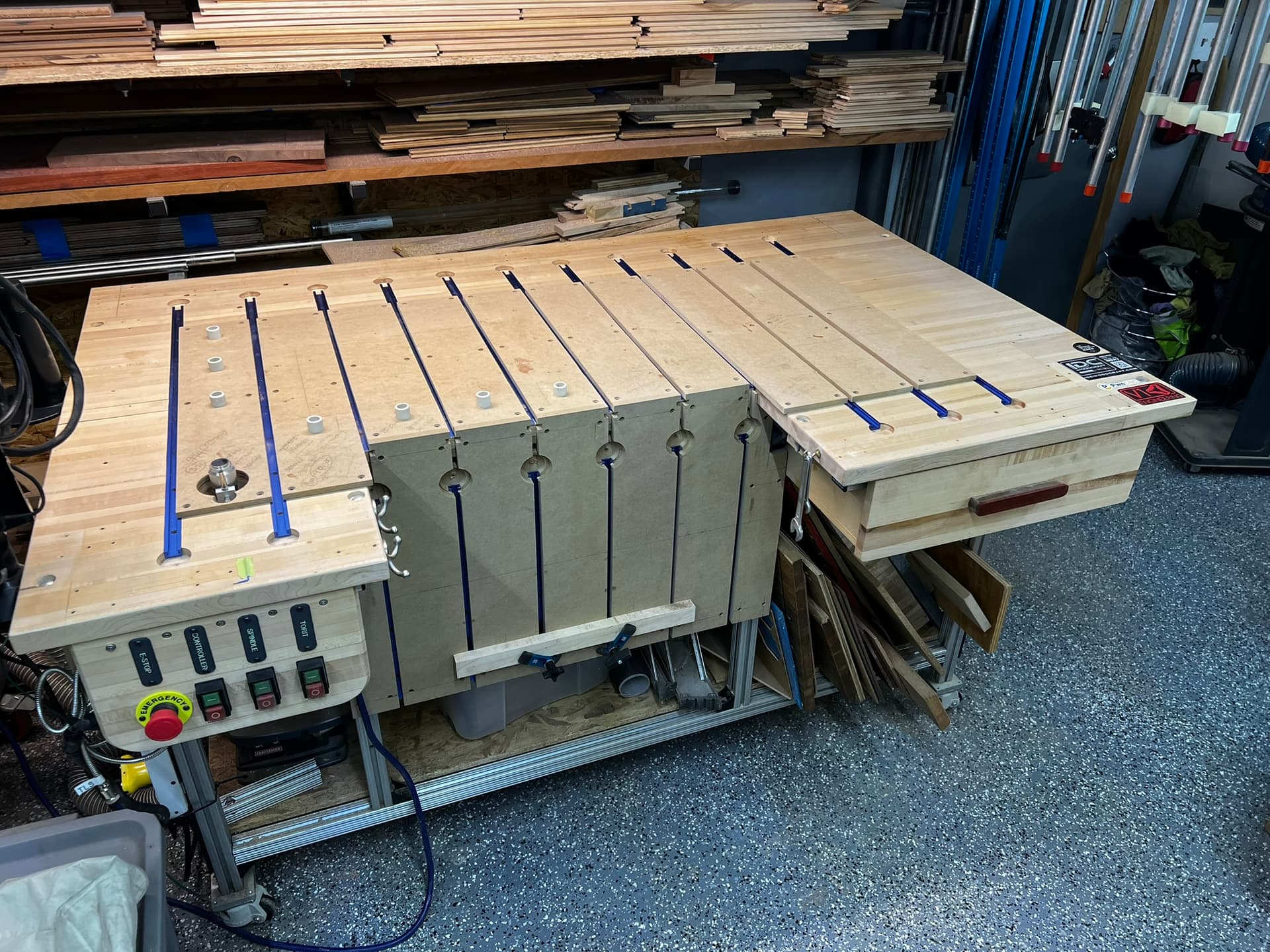
The Glow Rider V4 has a new home!
4 Likes
11 Likes
7 Likes
That is one hell of a fancy table! Hope you plan to make some cool looking joinery with that set up!
1 Like
I love that table. Every time I see it I think about how I want to configure something like that vertical clamping section.
4 Likes
That is a very nice table and a very nice build!
1 Like
?ets Jul 29 2019 12:21:46
rst:0xc (SW_CPU_RESET),boot:0x13 (SPI_FAST_FLASH_BOOT)
configsip: 0, SPIWP:0xee
clk_drv:0x00,q_drv:0x00,d_drv:0x00,cs0_drv:0x00,hd_drv:0x00,wp_drv:0x00
mode:DIO, clock div:1
load:0x3fff0030,len:1184
load:0x40078000,len:13260
load:0x40080400,len:3028
entry 0x400805e4
[0x18]
Brownout detector was triggered
ets Jul 29 2019 12:21:46
rst:0xc (SW_CPU_RESET),boot:0x13 (SPI_FAST_FLASH_BOOT)
configsip: 0, SPIWP:0xee
clk_drv:0x00,q_drv:0x00,d_drv:0x00,cs0_drv:0x00,hd_drv:0x00,wp_drv:0x00
mode:DIO, clock div:1
load:0x3fff0030,len:1184
load:0x40078000,len:13260
load:0x40080400,len:3028
entry 0x400805e4
Brownout detector was triggered
ets Jul 29 2019 12:21:46
rst:0xc (SW_CPU_RESET),boot:0x13 (SPI_FAST_FLASH_BOOT)
configsip: 0, SPIWP:0xee
clk_drv:0x00,q_drv:0x0�[0x5]
My Fluid dial was not working in the JP3 RJ11 so I plugged in the rj11 module from Bart and got a “flashing” on/off when I booted up the JP3. I think I may have fried the JP3
1 Like
Have I told you all that I hate/fear the Electronics side of this CNC stuff.
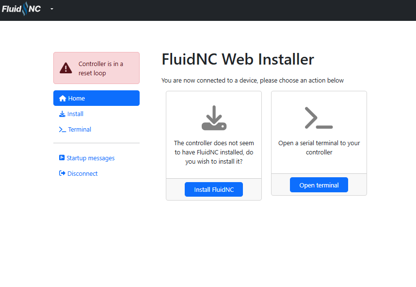
I have flashed the ESP and Factory Reset it and Loaded Fluidnc a couple of times but the “Controller is in reset loop” persists.
“play stupid games win stupid prizes!” <<< That saying was meant for me.
How did you wire the FluidDial pendant?
It was working on the JP1 with the FluidDial RJ12 Wiring Kit
https://www.elecrow.com/fluiddial-rj12-wiring-kit.html
Questions:
-
Should the Fluiddial work connected to the JP3 Rj11 with the out of the box Cinfig.yaml file?
-
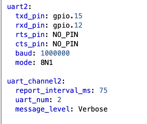
Do I need to change the Config.yaml file to enable the pendant?
-
The documentation says that the RJ11 on the JP3 shares gpio.12 and gpio.15 with the expansion module I assume that the standard configuration of pins on the JP3 Rj11 have rx and tx in the correct or same position as the RJ11 module from Bart is that correct?
-
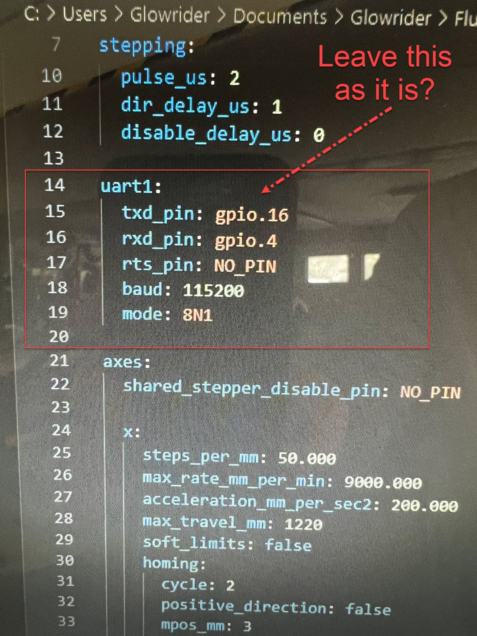
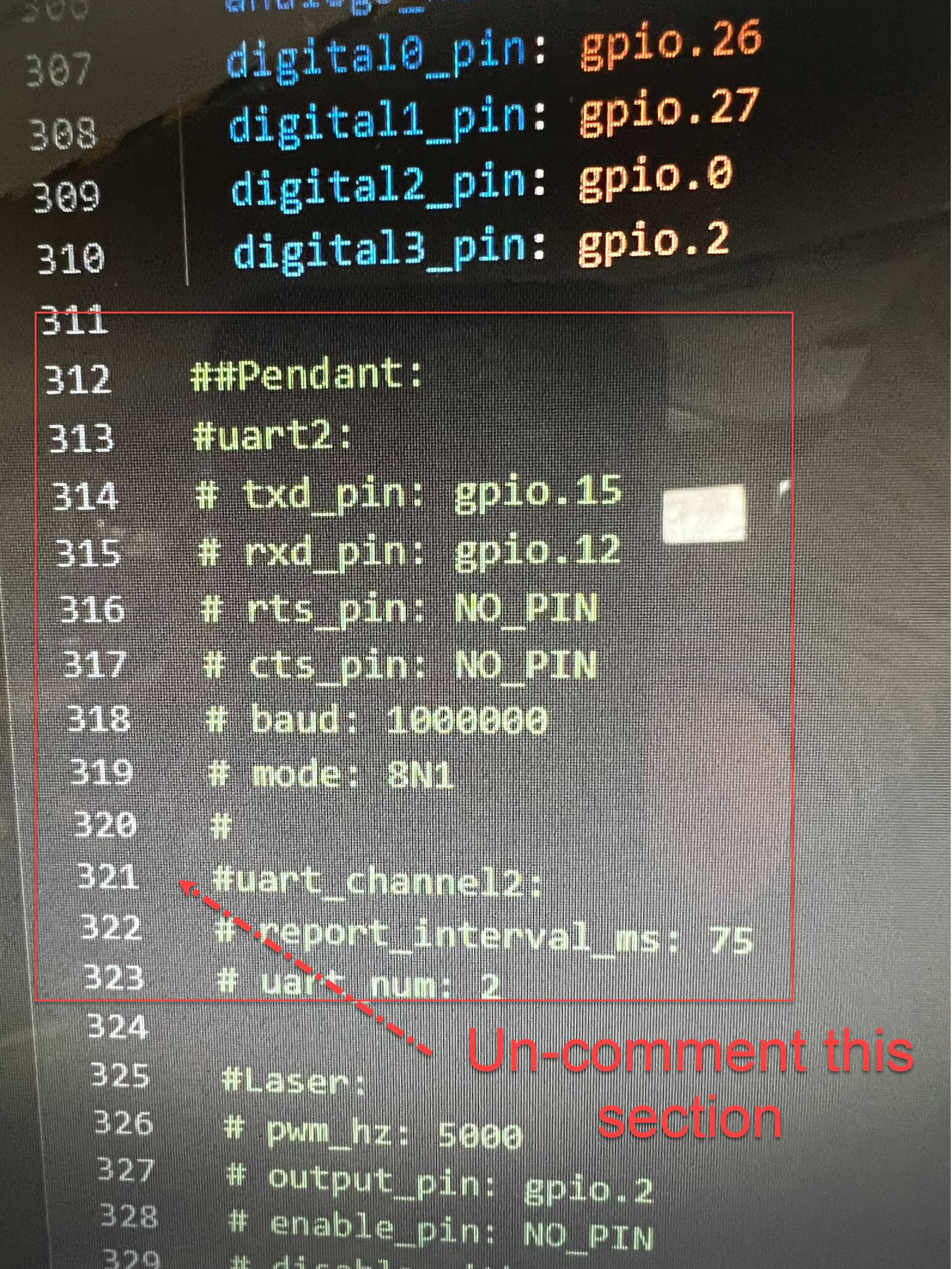
The stock Config file has no reference to gpio 12 and gpio 15 except for the commented out section for the pendant
If I uncomment the ##Pendant section and save and load this modified config file, I get lots of error messages >>> Which led me down the path to trying to get it working and ended with the JP3 fried
1 Like
and leave the UART 1 section as it is
1 Like