GCode/Step tuning questions

So I went into EstlCam and set up a square that was 50mm x 50mm. Made it 8mm deep.

My end result was 81.38mm across and 16.48mm deep. On the plus side, the finish was nice… :slight_smile:

My options, as far as I can tell, are:

  1. Recompile Marlin with the corrected step values
  2. Manually adjust the step values with M92 commands
  3. Adjust the Scale in EstlCam

Is there anything else I could be missing, as far as possible causes?

So the last one just seems like a bad idea, because it won’t fix it for anything else. So I’m figuring I’ll re-calculate my steps/mm, set the values temporarily with the M92 command, and once that’s fixed, re-compile the firmware and flash that.

And if my current DEFAULT_AXIS_STEPS_PER_UNIT is {80, 80, 400, 500} (don’t know why we need a 500?), then my new values are {49.152, 49.152, 193.94}, right?

Or do I need to change my micro-steps or something like that instead?

Clint

You don’t need to reflash it. You can save it with M500.

Instead of using a cut to measure, just make a 100mm move and measure how far it moves.

The values should probably be 50,50,200. They are usually round numbers. But what kind of setup do you have to get those numbers? 1/8th microstepping?

A lot of scale problems occur when importing the SVG into Estlcam - that’s why Jeff suggests just using the LCD to move the bit.

Alternately, you can click with the mouse wheel to take measurements in Estlcam - or set up a grid for a rough ‘sanity check’ of your imported image.

I do have a grid set up in EstlCAM. It is set to 10mm/square, and my square takes up 5 square. Plus when I click on “Resize” and click on my square, it says X and Y are both 50mm. Plus when I look at my gcode file, it shows that it’s trying to move 50 units. So I’m pretty sure my scaling is correct.

I thought I was nailing it down last night, but then when I fired things up this morning to try to finish tuning, the first square was like 22mm across. Like WTF? So I recalculated, and ended up with values of 100 for each of X and Y (default steps per unit). Jeff, I honestly don’t know what my microstepping is set to… Didn’t touch that. I’m using the TMC2209 drivers, and the “MICROSTEP_MODES” in my Configuration_adv.h are set to 16 all around.

And the reason for doing a square was to get both the X and Y axis together. The whole point in general was to emulate the “test cube” that I did when I first set up my 3d printer, where you’d use the X/Y/Z values to tune the steps.

Thanks, all!

Clint

That sounds like you’ve thoroughly eliminated Inkscape as a possibility :smiley:
While I’m asking silly questions; presumably you’ve got the usual 16tooth pulleys, 2mm belt and 1.8 degree motors? (so 32mm and 200 steps per rotation)

Should the tool move 50mm to cut a 50mm square? What about the width of the bit?
If you’re using a 3mm bit to cut a 50mm pocket, it would have to start at 1.5mm and cut to 48.5mm. If the gcode went from 0 to 50, you’d get a 53mm pocket.

I would have thought that getting the wrong microstepping mode setting would only put you out by a power of 2, not a strange fraction like 81/50.

Test cubes make sense for 3D printers, where you don’t want to wait ages and waste loads of filament, but for a CNC it’s more accurate to use the LCD to move the tool almost as far as it will go, measure that with a ruler and compare it to the numbers on the LCD. The further you go, the smaller effect your measurement error has - and by controlling it manually, you don’t risk crashing at the end.

Yes, I ordered the 16 tooth pulleys, 2mm grooved belt, and 1.8 degree motors.

And sorry for not being precise (since our CNC machines are designed to be precise). The actual movement from one corner to the other is 52mm, and my bit is set up as a 4mm bit. I was focusing on the fact that it wasn’t trying to move 80mm.

So I just tried the Octoprint drill/move/drill manuever. Aside from screwing up a couple times by trying to drill through my countertop (make sure to set the Z movement to 1mm, not 100!), I ended up coming up with a value right around 100 (99.8, to be precise). I’m going to try re-compiling Marlin and flashing with those values, and see what happens.

I’ve got to say, you did get me rethinking things… When I ordered my stuff, my belt came with 20 tooth pulleys, and I was worried I used the wrong pulleys. But I took off one of the pulleys and counted the teeth, so that’s good.

I AM using an SKR 1.1 Pro board, so it’s possible I have missed something.

Thanks for your input!

Clint

I’ve posted the procedure I use to calibrate my machines several times (here and here)… and verified the procedure with accurately engraved rulers after calibration.

Finally, I finally found another fellow doing the same procedure…

The “meat” of the procedure is between the 3:00 and 5:30 minute marks. No need to know anything about the drive system, micro-steps, numbers of teeth, belt pitch, bit diameter (just need something with a point), or anything else… just lay out a good tape measure or metal meter/yard stick and command as big a move as your axis allows. Measure how far it actually moves. Then multiply the current steps/mm setting by the ratio of commanded to measured… to get the new steps/mm setting. And don’t worry if the number you come up with is not “round”… it’s okay if it’s not. I must also disagree a bit with those who maintain that “round numbers” are good enough… try printing a few rulers and see the difference a fraction of a step makes. :astonished: :wink: :thinking:

Interestingly, he goes on to say he got started with MPCNC… and graduated to the wimpy little machine he’s using now :grin:

I prefer the round numbers, unless you are calibrating at the same scale as the final product. If your calibration includes a few tenths of mm of backlash or something, then you can make it dead on for the 50mm you tested, but is that better or worse than the round number at 200mm? What about 1500mm on a low rider?

I didn’t mention it here but it is imperative, that whatever “error”/slop/etc in your system, that you get consistent, repeatable, results for a given movement command… or this procedure cannot give the accurate results you are looking for; i.e. something somewhere is loose/broken to cause the inconsistency and needs to be addressed before trying to calibrate.

The point he’s making here – and I agree with him – is that this procedure is doing exactly what the manufacturers recommend (I think the Mach folks do the actual calculation for you in their software) but doing it over the entirety of the axis, rather than over some random 50mm section. You can start with small movements at first when you aren’t sure you’re not gonna crash… but once close, do it over the entire extent of the axis for best accuracy.

Again, the key is that whatever your machine is doing… it must be doing it consistently and repeatably. If so, then you can compensate for it.

If round numbers are good/close enough for you… then that’s fine. I personally have seen, time and again, the difference a fraction of a step can make in the steps/mm setting in the work I’ve been doing. I find this procedure to be quick, easy, accurate… and I can’t see that handling the fractional part causes the firmware any heartburn at all.

1 Like

I am not too worried about 99.8 when the round number is 100. Especially if you have already used your machine for a while. I am more worried about someone choosing 91.453 when it should be 100. They probably don’t realize that something else is wrong or broken and they are masking it by calibration which makes it 2x harder to uncover the real error.

It can be very easy (especially for 3D printer users) to try to calibrate a 20mm square and end up a few percent off, which will really end up in a mess at 24". Or they might have something wrong and not know it.

The belts do stretch, but that is the only proportional error. If the belts are steel and broken, or a loose screw or the rollers are rocking, will all be a set error that will be added to any position error. If you calibrate it out at 20mm, you will be over compensating at 40mm+.

I think we are in agreement on the facts, just maybe not coming to the same conclusion for the first machine calibration.

1 Like

I think we’re in agreement on the facts as well, Jeff. But you’re a very generous, knowledgeable, and patient troubleshooter… who’s thinking about trying to help a multitude of new users get a basic machine built, and who are facing myriad problems. And I really do admire and appreciate that in you… we/they need you. But that’s a wide-open scenario, with folks with little/no experience still trying just to get some semblance of basic operation… often with all axes at once, with an end-mill already chucked up, and ready to plunge into a piece of steel/aluminum. That scenario is far more wide open, and volatile, than simply, “I want to calibrate my MPCNC”… the scenario I’m responding to.

Speaking as a fairly experienced builder, with the simpler scenario, and given consistent and repeatable motion from the machine in front of me… I use this procedure as soon as I can get an axis moving consistently. The R&P MPCNC was a good example… I really didn’t know – or care – the actual pitch of the printed rack and pinion teeth or even the step/mm settings installed on the controller I happened to pick up out of my stash. It was a very simple matter to just lay a ruler on the worksurface, rubber-band a skewer to the carriage, with the point just above a major division on the ruler, and then command a small, but easily measurable, move. It was immediately obvious how much it was off and a new – quite close – steps/mm value was easily calculated. And, with one axis runnng nicely, I was off and running (this is the way I roll :wink:)…

I don’t mess too much with my 3d printers… especially after getting my first Prusa. The myriad extrusion and molten plastic issues are far less predictable and often greatly affect, and show up, in minute ways, in any apparent axis movement and render a pure calibration of the axis movement impossible… so I don’t recommend this procedure for 3d printers, especially with taking measurements off printed calibration cubes.

But I do have a lot of other DIY machines to mess with… and they are the ones I use this procedure with, a lot. I often change CNC controller boards, firmware (Marlin, Grbl, LinuxCNC), drive mechanics (belt, leadscrew, r&p), and tools (needle cutter, laser, pen, router)… often just to have something new/different to play with for a while (a necessity at my age). But KEY in my thinking… if ALL my machines are calibrated to the SAME INCH/CM standard – as close as I can possibly get it – the parts I produce on one machine will match, and mate up with, parts from another machine. And that is incredibly gratifying/satifying to the little bit of “engineer” that’s still left in me.

I don’t really want to hijack this thread and I think I’ve said what I needed to say, so I’ll shut up. But I really do appreciate all the support, from generous and knowledgeable folks in this forum (you too, Jeff :wink:)… that’s what makes this place special and why I spend so much time here. If everybody was “tunnel-visioned” as I am… we’d all be in trouble.

5 Likes

Well said. Thanks.

3 Likes

Thanks for the conversation, guys!

As far as my tuning issues go, I’m about ready to throw in the towel on this SKR 1.1 Pro board, and order an MKS Ramps 1.4 board instead. Was trying to get my Z probe working on the Z-min endstop, and can’t get it to register as triggered (M119) no matter what I do. Endstop pin is configured in firmware, but no joy. And I still want to hook up my spindle on a relay, which I’m willing to bet will be another headache.

I would have ordered directly from Ryan, but the shipping ($50US) and exchange (40%!!) really makes that unfeasible. No fault of Ryan or anything, just the way things are.

I did end up slowing down my movements a lot, and slowing down the acceleration as well. That does seem to help the movement in general.

Clint

I wanted to jump in here in hopes to get a little more clarification on what appears to be some common issues i share with CNeufeld.

To get this out of the way I’m using the following:
Arduino mega with Ramps 1.4 dvr8825 drivers, Nema 17, Gt2 belt, and 16t GT2 pully.
Currently using dw660 was using dremel3000.
All the standard stuff.

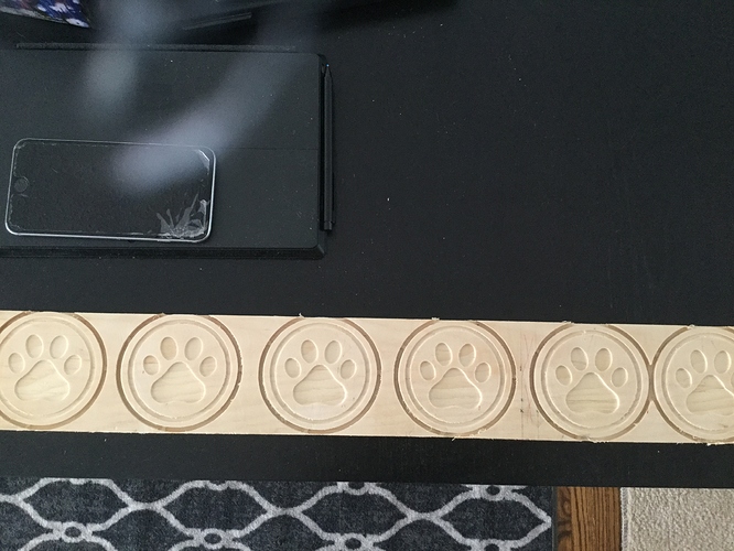
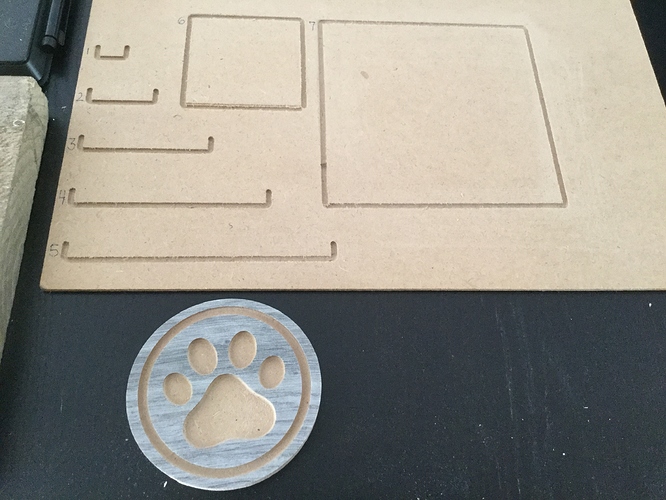
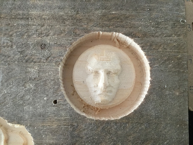
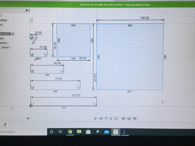
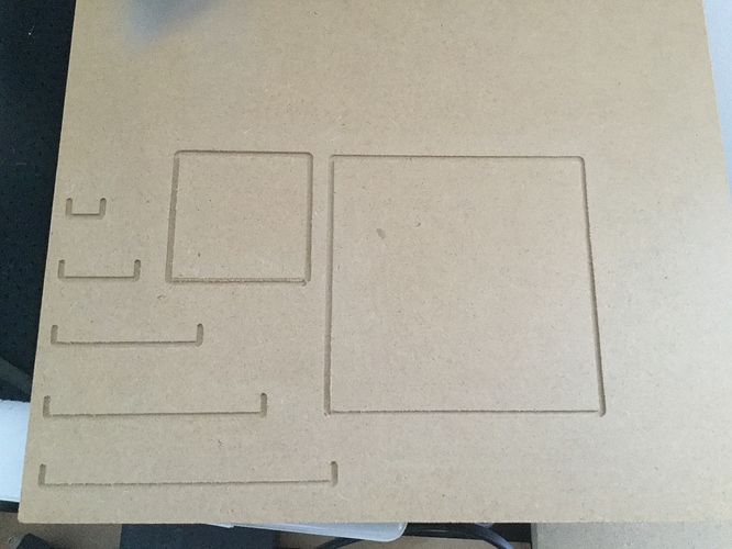
Attached are some pictures of some dog paw coasters a relief and a measure test.
I know my measurements are off and also know its not fusion360 or estlcam.
I have zero issues with plunge depth the z axis is fine.
Its the x and y axis i have issues with sizing. 100mm is 131mm when i move the x or y axis. this explains everything to me when I couldnt figure out why everything I was making was larger.
I use an lcd to operate controls as a laptop in the area for me is not feasable.
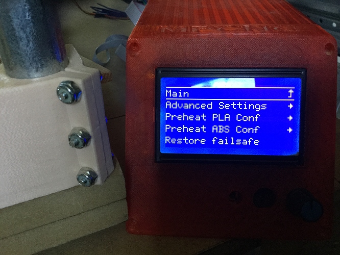
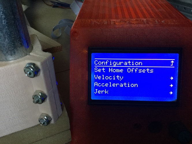
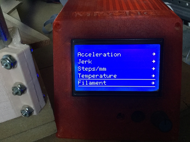
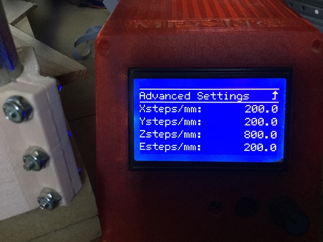
Q: Can i make step adjustments through the lcd and advanced settings?
As knowledgeable as it is to know the importance of a properly calibrated table some of us need the steps to achieve such a task with the mpcnc.
Other than that the machine is great things are just coming out over sized. I have played around with resizing in estlcam and find I’m getting closer to the size at 70% the original file.

actual measurements:

13.62
34.02
67.16
99.79
132.86
66.82 x 66.82
131.86 x 131.86
give or take

I don’t want to sound ungrateful, there is a lot of great information in the thread but i cant seem to find the answer and I hope to leave scaling my designs to 70 percent behind.
I clearly have a stepping issue and would like to fix it, even better yet i would like to understand the fix.

2 Likes

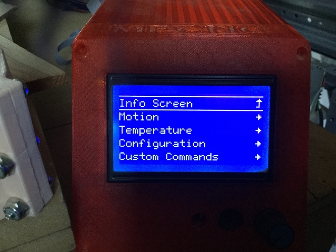
Yes. It is in the configuration menu. Make sure you save the settings afterward, or it will reset after you power cycle.

33% is suspiciously round, and very far off. I wonder what your steps/mm are set to now. Are you sure you don’t have 20T pulleys or something?

You can definitely calibrate most of that out. But if it were me, I would definitely want to know where that error was coming from. I would be counting the number of teeth in 20cm and checking the teeth and the model numbers on the steppers.

But you can certainly just reduce the steps/mm by 33% or so and get it figured out. They should be 200steps/mm, I think. With drv8825s, and all the jumpers under the drivers.

So after tinkering with the steps quickly i have the steps down to 151.5 and 152.5 and its almost perfect, I will spend a little time later getting it spot on but have the general idea now.

One last thing how do I save the settings once I have finished so it doesn’t reset after the power cycle.

There is an option in the bottom of the configuration menu. It might be called, “save eeprom”

I can’t seem to locate save eeprom anywhere.
Any guidance would be appreciated.

I see now i have an update to do. Will keep you posted and thanks again for your help.

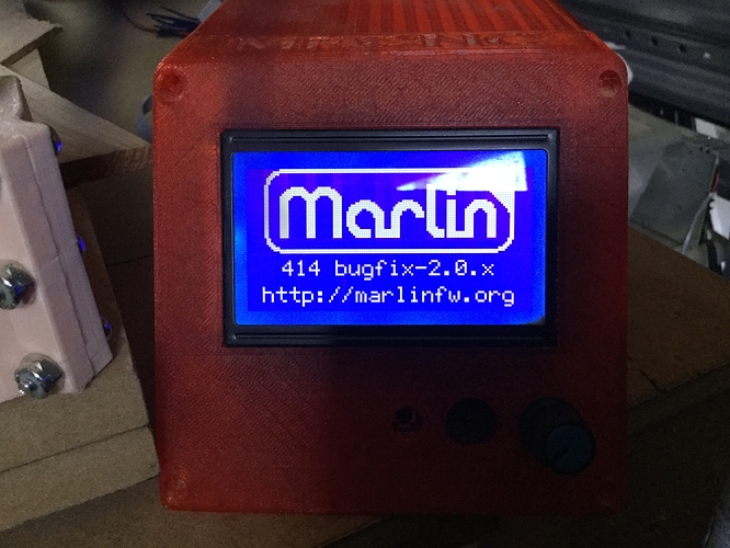
I think 414 might have been the version without eeprom enabled…

You can flash the firmware with the right settings, and enable eeprom.

If you don’t want to mess with that, you could use M92 to set it via gcode. You can put a file with this in it and put it on the sd card:

M92 X151.5 Y152.5

I think there is a special file that will be executed automatically auto0.g

It is a bit of a hack, but it should be easy.

Problem solved. I just went into the configuration.h file and activated the eeprom. Save feature now accessible, thanks for the assistance.