I’ll see if I cant figure something out once my machine is together. I like playing with dust collection systems for crazy reason. I hate fluid dynamics and these are 100% about fluid dynamics. That being said, I’ll see what I can come up with once I’m built. Oredered in all the electronics and jackpot board today. and I’m done printing for now. I still need all the clips for the y rail, but I’m holding off until I get a slightly better picture of what I really want to do.
1 Like
honestly, I think the answer is redesign the tool mount to incorporate the dust collection, then have a drop down floating Z shoe from there. Think of Daniel’s costume in Karate Kid. But Im only 3 sips into my coffee this morning so I might even be typing in gibberish right now.
2 Likes
I like the way you’re thinking here. I think sometime soon, Ryan may let us see what direction he’s thinking on it.
I really can’t hate on the clogs too much… The original shoe on my machine didn’t pick up anything at all until the end mill was like 3/4" deep into the material, so not much chance of a clog there. I’m still hoping that a material that puts out more regular wood chips will flow much easier, but I’m always excited to see what you and @vicious1 come up with in the future.
1 Like
I can’t remember if I showed this yet, but another thread caught my eye about how you could pretty much Z-calibrate off of anything and I tried the tiny touch plate, which can worked fine, except I have these gigantic man hands that make fitting them under the router and holding that plate in place kind of crazy. I should mention the tiny touch plate is so light that any bends in the wire will flex and pull it out from under the bit…
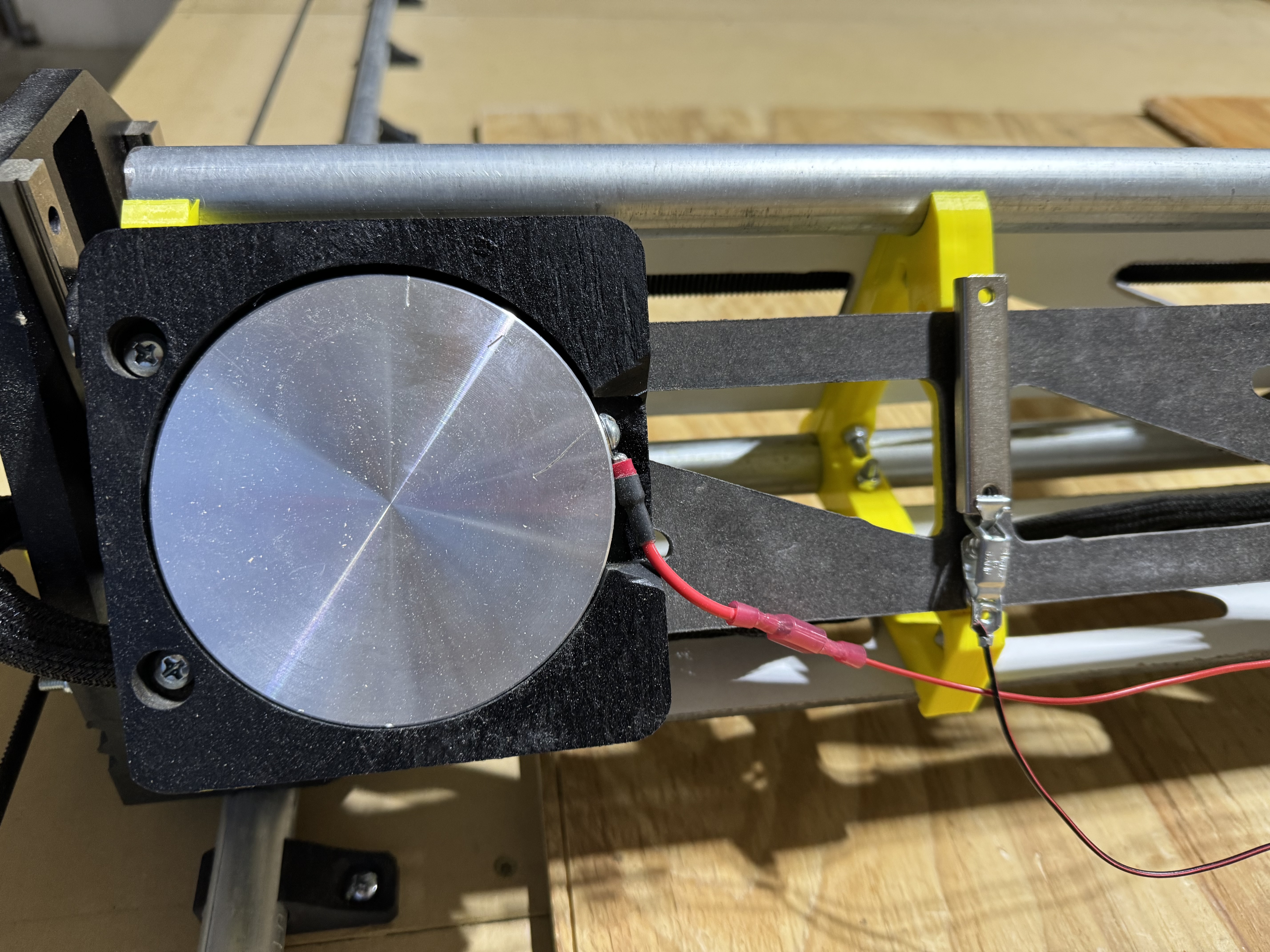
I wanted a plate with some heft to it so I could just drop it down there and leave it until the z-calibration was done. The plate is a 10mm thick 100mm diameter aluminum plate that I drilled and tapped to attach the lead. Also, the magnet was a great idea, but again, bear paws… so I went to Amazon and grabbed a 2.5” neodymium bar magnet so I could just blindly flail around down there and attach to something. (I do take a step back after to make sure it attached to the bit or collet nut)
I think my mind was looking towards an XYZ calibration in the future and I would just mill the plate into a 90 degree corner with a 5mm step in from all three sides. However, accounting for bit diameter math in the post processor code is not a today kind of problem.
Well then I had to find somewhere to put these things where they wouldn’t drag, so then I had to cnc a base mount and paint it to match… the magnet happily sticks to a bolt close by.

5 Likes
I love this solution. I may do something very similar.
I was contemplating something like this, but the main reason I went low rider instead of mpcnc is that I want to be able mill down perfectly flat surfaces on slabs. By referencing the bed, I would have to account for slab thicknesses each and every single time I went to use it. So referencing the top of the material is much easier for repeatability. But with something like you have done, I can set big hunk of metal on the material and just have the known thickness of hunk o’ metal be my offset. In your case 10mm.
I did think about a plate on rods of some sort. So its always in place but I can easily just raise it up, to the height of the work piece and go from there. But I keep coming up with more steps than the normal way everyone else does it.
problem with this is you don’t always have the bit at the exact same depth in the router. so with the touch plate it references the top of the material AND the bottom of the bit. Everything taken into account in one shot. And when its all set in your starting gcode to probe and set the offset of your probe thickness it gets real simple
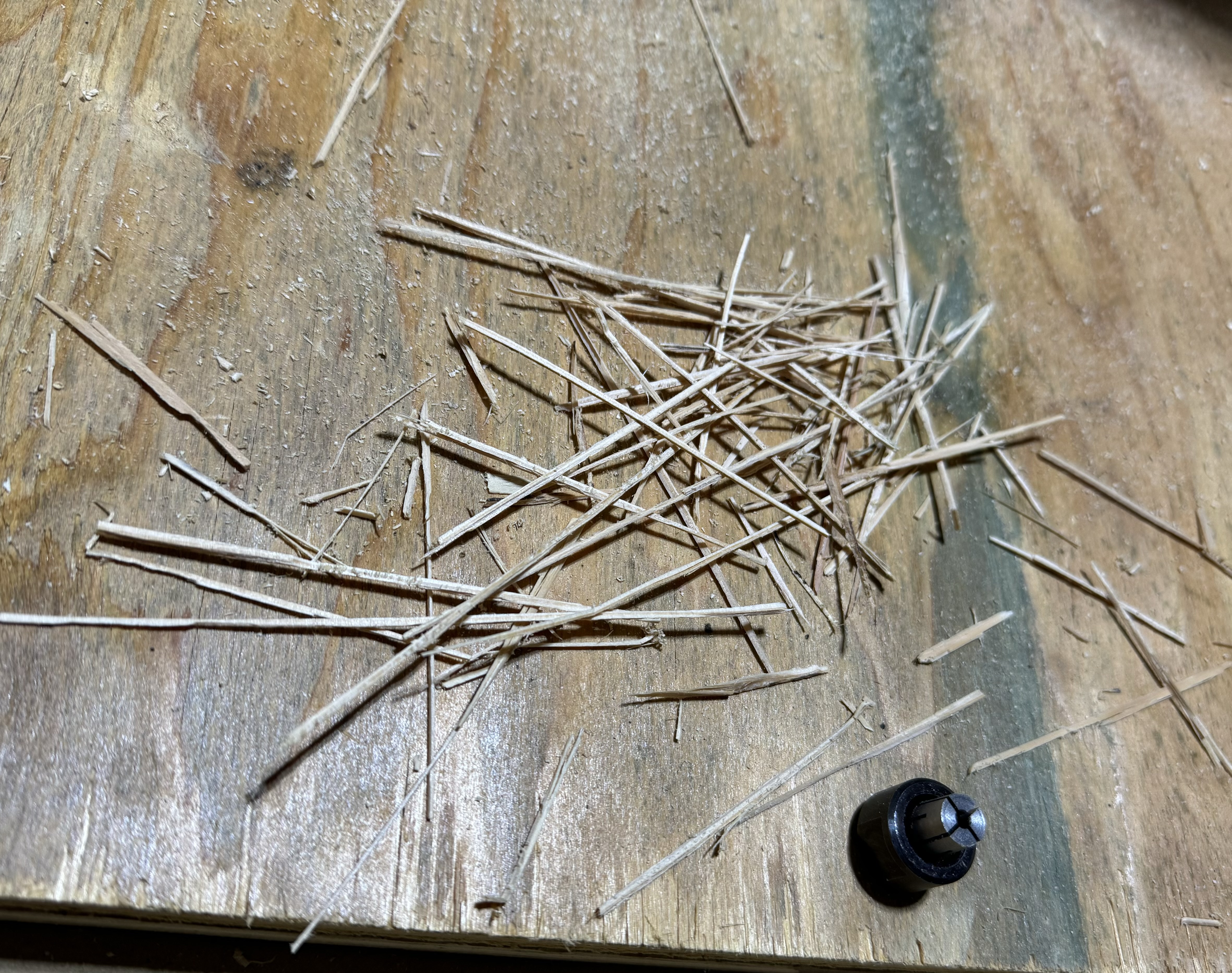
I did another cut this morning with that same wood to get rid of it. The splinters are bad enough that they yanked my bristles out of the slot… more glue I guess.
By the way, when I say wood splinters, this is what I’m talking about… random extra collet nut for scale, lol.
1 Like
I agree with you on the splinters, I have had to pause to clear a clog many times. The ones with the bottom more open weren’t near an issue with the clogging. They would catch the splinters sure because they just cant make the turn but it wouldn’t let the splinters catch all of the dust around them and clog. I need to find the original open bottom one I had and run it some more. See if it gets as much dust as the latest one does. Actually I think ill go back and print one of the half open ones. I think that would be a better deal. and if it has room to attach the new bubble butt thing @DougJoseph made that might be a better deal all around.
1 Like
I printed the “Sloping Ramping Bubble Bumper” thing and glued it on to my dust shoe, and it seems to work exactly like I hoped it would. It was able to allow the dust shoe to elevate up above high material-holding sidewalls like 5-6-7 mm taller than material, and even over a screw protruding on top of the sidewall.
1 Like
This one works great on MDF… no splinters = no problems.

I’m probably just going to print a second shoe and switch out based on material.
3 Likes
Everything was running great and I got a bunch of stuff done today and then… failure.
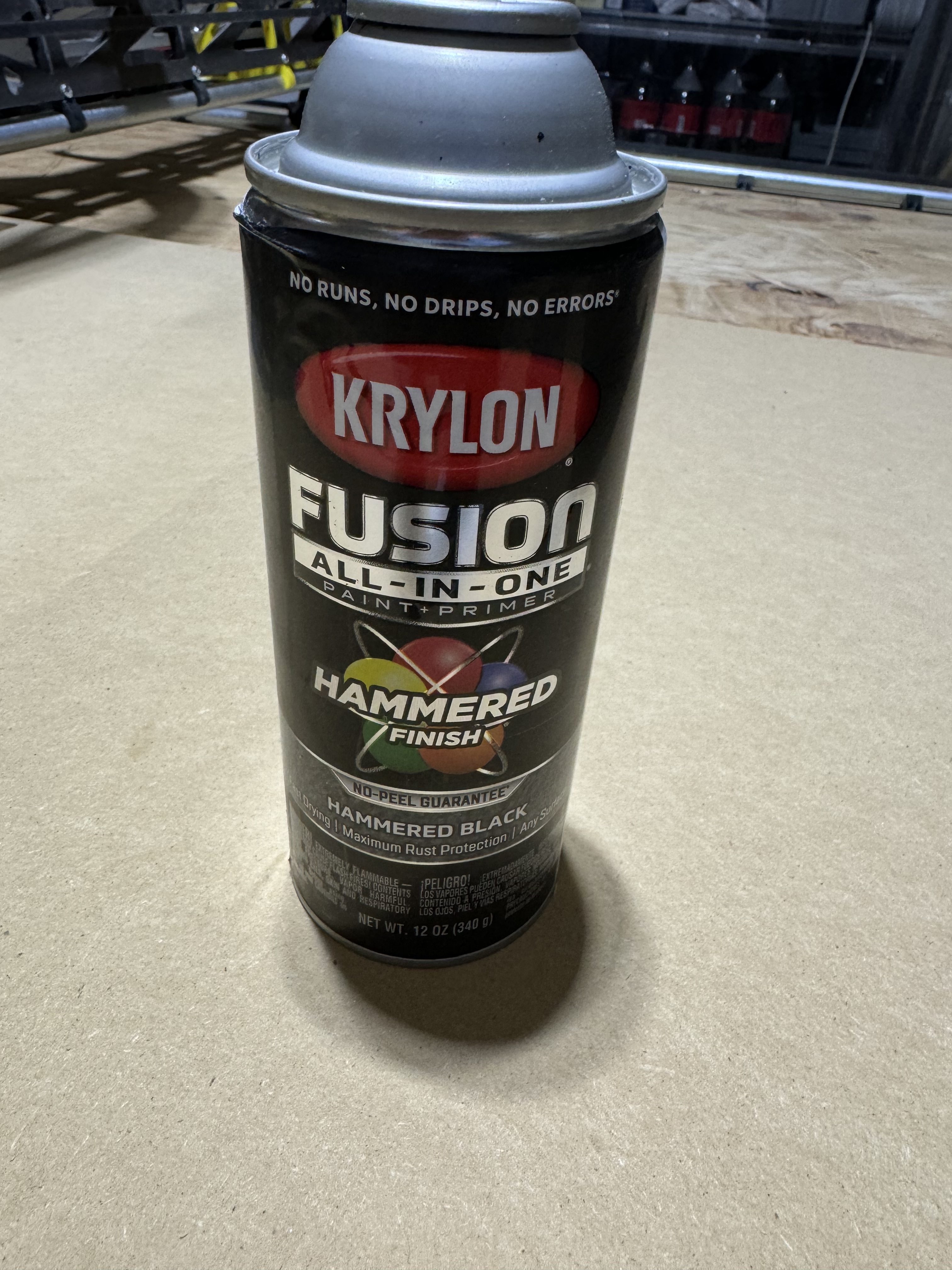
My wife is getting a promotion at work, so I wanted to make her a sign for her office door. Got it all mput together in Fusion 360, painted the MDF surface (Krylon Hammered Black) and went to work on the engraving and cutting paths and… crap!
1 - The design engraved backwards…
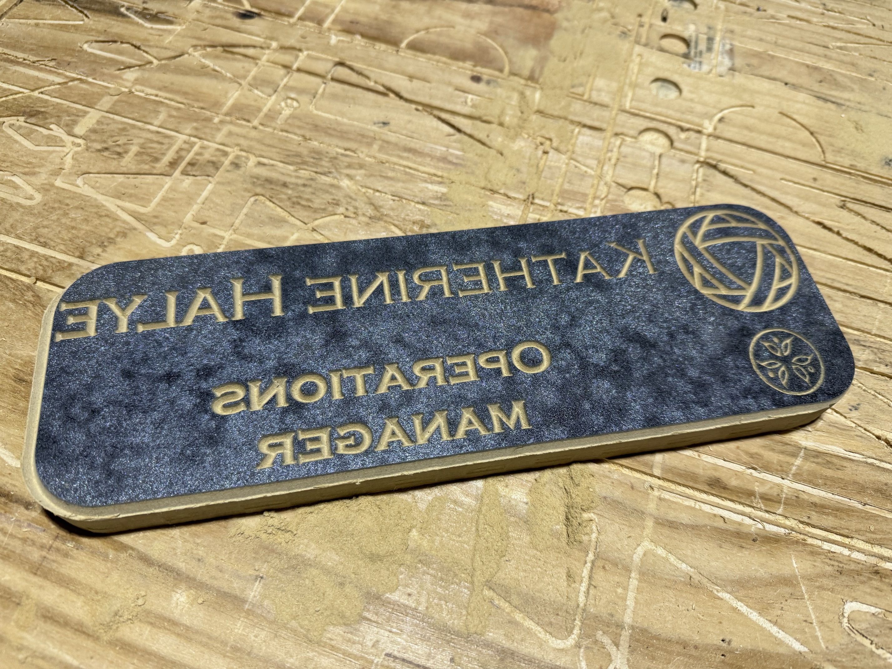
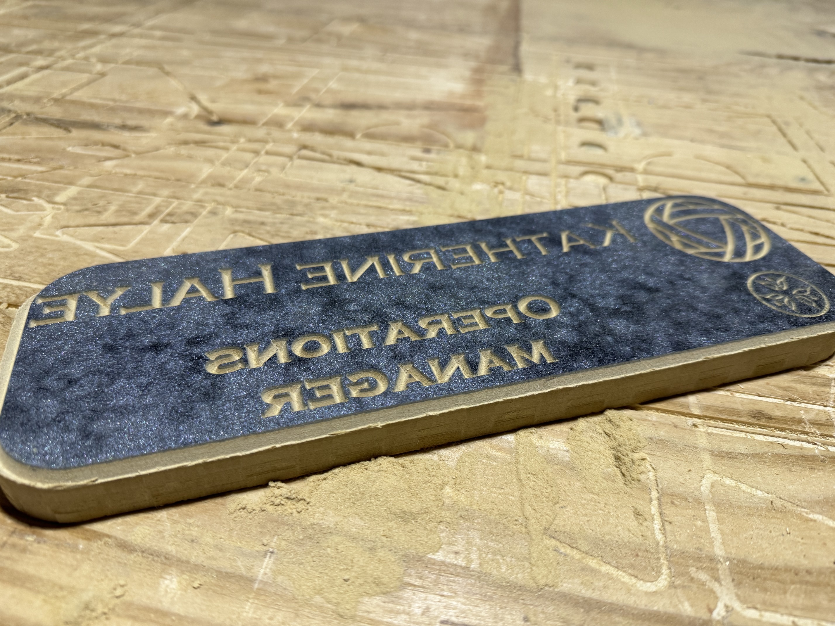
Anyone know what’s up with this and how to fix it? I’m not opposed to pushing this job into EstlCam or Carbide Create if it makes more sense over there, but I’d like to know why Fusion thinks I want this mirrored…
2 - then the bit change failed the z-calibration and I had to reset the controller to make it stop trying to drive the bit through my z-plate
This one is my fault, I didn’t have a solid magnetic lock on the collet nut, took me 3 tries to figure that out because it looked like it was on there…
3 - that caused the motors to shut down and I lost my x/y positions by a few mm just by putting the dust shoe back on…
Is there g-code to engage the motors when I restart in case I need to immediately lock positioning again?
This can happen jf your axes are wrong.
The LR3 is designed asauming you stand at the end facing the beam lookjng at the router.
- X+ moves to your right.
- Y+ moves away from you
- Z+ movez up from the bed.
One of these reversed means yoj get mirror.kmages of things. Same with 3D printing.
M17 should immediately engage the steppers in both Marlin and GRBL, which covers V1 supported boards. (I think it works for RepRap firmware, too.)
3 Likes
Well shit… I’ve been operating under Y+ moving towards the foot of the table (towards me if I’m facing the router side of the gantry)…. Everything else matches what you said.
Ok, need to flip the Y motor connections around and reset all my Fusion 360 CAM setups… and try it all again.
So if I have to reboot, I can just hit M17 {Enter} and all the motors will lock like they do after a job is finished or paused for tool change?
2 Likes
I think that’s correct. If you are on an SKR with a TFT, you can tap into the terminal screen to issue the command. If you find yourself needing to do a certain command a lot, there are ways to add a button for it. But unlike the Jackpot’s ease of creating buttons for macros, on the BTT TFT, editing the buttons requires some code editing and recompiling of firmware.
This is one of those threads that I’m so glad I’m reading. So many of the things you are dealing with will be issues for me and I’m learning in advance. Thank you for posting all your questions and thank you to everyone for answering in ways a complete newb can understand.
2 Likes
I’m so glad all of my neurotic flailing about is helpful to someone ![]()
![]() . I’m honestly happy to be part of this community where I can literally watch progress happening daily and where the other builders are willing to offer help. I’m just getting to the exciting part now where I start building the confidence in the equipment and my designs to try new things.
. I’m honestly happy to be part of this community where I can literally watch progress happening daily and where the other builders are willing to offer help. I’m just getting to the exciting part now where I start building the confidence in the equipment and my designs to try new things.
First up this weekend are some practical tests on the new IDC Woodcraft “Beast” and “Badger” roughing bits and hopefully a successful build of my wife’s office door sign.
My goal for February is to throw a whole 4x8 sheet of plywood on the table and cut some cabinets for the garage with zero issues.
Once I get the garage reorganization stuff done, it’ll be on to 3D relief and engraving experimentation. Good thing I already have two tapered ball nose bits (1/8, 1/16) and two V carving bits (60°/90°) ready to go. I have an idea for a cigar ash tray for a friend and a Navy service flag with a USS Ranger aircraft carrier for my father in law.
3 Likes
Here’s the new video with the easy add-on that enhances the Floating-Z Dust Shoe:

Printables listing for the Floating Z Dust Shoe (v1.1) contains the STL for the bubble bumper thing:
https://www.printables.com/model/625802-new-for-3-makes-of-routers-lowrider-v3-floating-z-/files
2 Likes
Is there an STL file for the bubble bump? I’m not seeing one on Printables.
Yes, it is part of this listing:
https://www.printables.com/model/625802-new-for-3-makes-of-routers-lowrider-v3-floating-z-/files