Garage Shop Mobile Lowrider v3

I just finished building the 6’-10’ break-down table platform on Bora Centipede legs that stands up and breaks down in 20 minutes into three pieces and slides off into a corner. It should support work up to a full 4x8 sheet.

Now I’m just working on getting the final calibration and configuration details worked out to convert from my prior cnc over to this one.

Let me know what you think!


12 Likes


6 Likes

Nice!!!

Lots of questions come to mind -

What are the dimensions of the table when assembled?

How are you connecting the three table top pieces?

Are you experiencing any twist or unevenness in the table, with only the perimeter being reinforced (no torsion box support)?

How do you find the Bora Centipede legs for stability? They look like they might have a bit of wobble if you put any side pressure on them.

For the price ($100 CDN at Costco), I might consider the Centipede legs for my upcoming table build, but at 24" x 48", I might need two sets (one for each end of a 5’ x 10’ surface), although I see that they do have a 4’x8’ model that would probably work (for a lot more money, though)

1 Like

Love the black and yellow! Interesting table setup, too.

What are the dimensions of the table when assembled?
Full table once assembled is 120-in long x 7-in wide" x 31-in tall

How are you connecting the three table top pieces?
I have 1/4-20 threaded inserts on the undersides (2 on each side) with 3-in bolts and knob-ends between the three sections

Are you experiencing any twist or unevenness in the table, with only the perimeter being reinforced (no torsion box support)?
I am seeing a little unevenness across the centers between the bolt connections and im. probably going to throw a biscuit jointer at them at strategic locations to limit this.

How do you find the Bora Centipede legs for stability? They look like they might have a bit of wobble if you put any side pressure on them
I find the Bora legs very stable along the long (y) axis with a bit of wiggle along the short (x) axis. I have the 48x96 set sat on a very flat garage slab.

1 Like

Sorry about the delay but I went on vacation and then the software portion of this build threw me for a loop, a wild goose chase and then some other odd colloquialisms.

I had to figure out the post processor situation for Fusion 360 and then ended up modifying the MPCNC post-processor config heavily to make if work with my configuration.

I installed an IoT relay switch to power on the router and dust collector electronically via M106/M107 fan control. Also, my board wouldn’t let me use Fan2. After some thorough testing, only Fan0 responds to the M106/M107 commands and polarity was a fun issue when connecting it to the IoT…

I also installed the Z-axis probe with touch plate sensor and had to work out that G38.2 is the correct command for me…

Then I had to work out that my LowRider build only has 80 mm of Z-axis range, so a Z40 tool change command when using a 20 mm waste board and 20 mm work piece just pegs the Z-axis out every time…

The rest is just my inexperience with Fusion 360’s CAM software settings and getting the orientation and start points set right and not trying to drive the gantry off the top of the table.


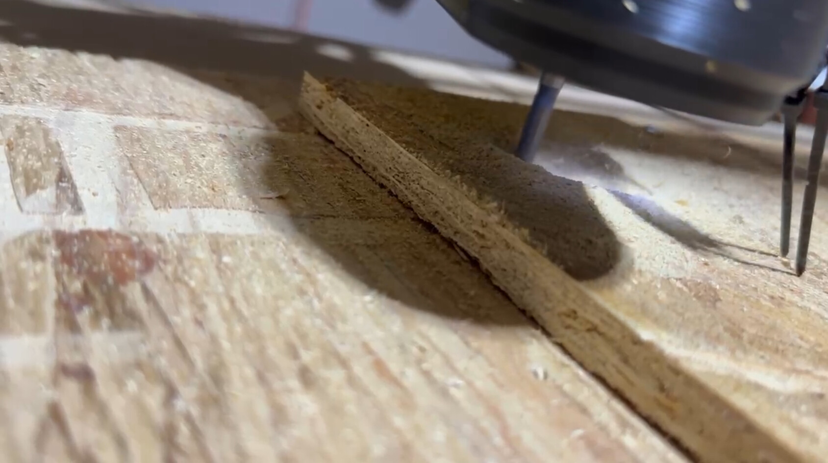
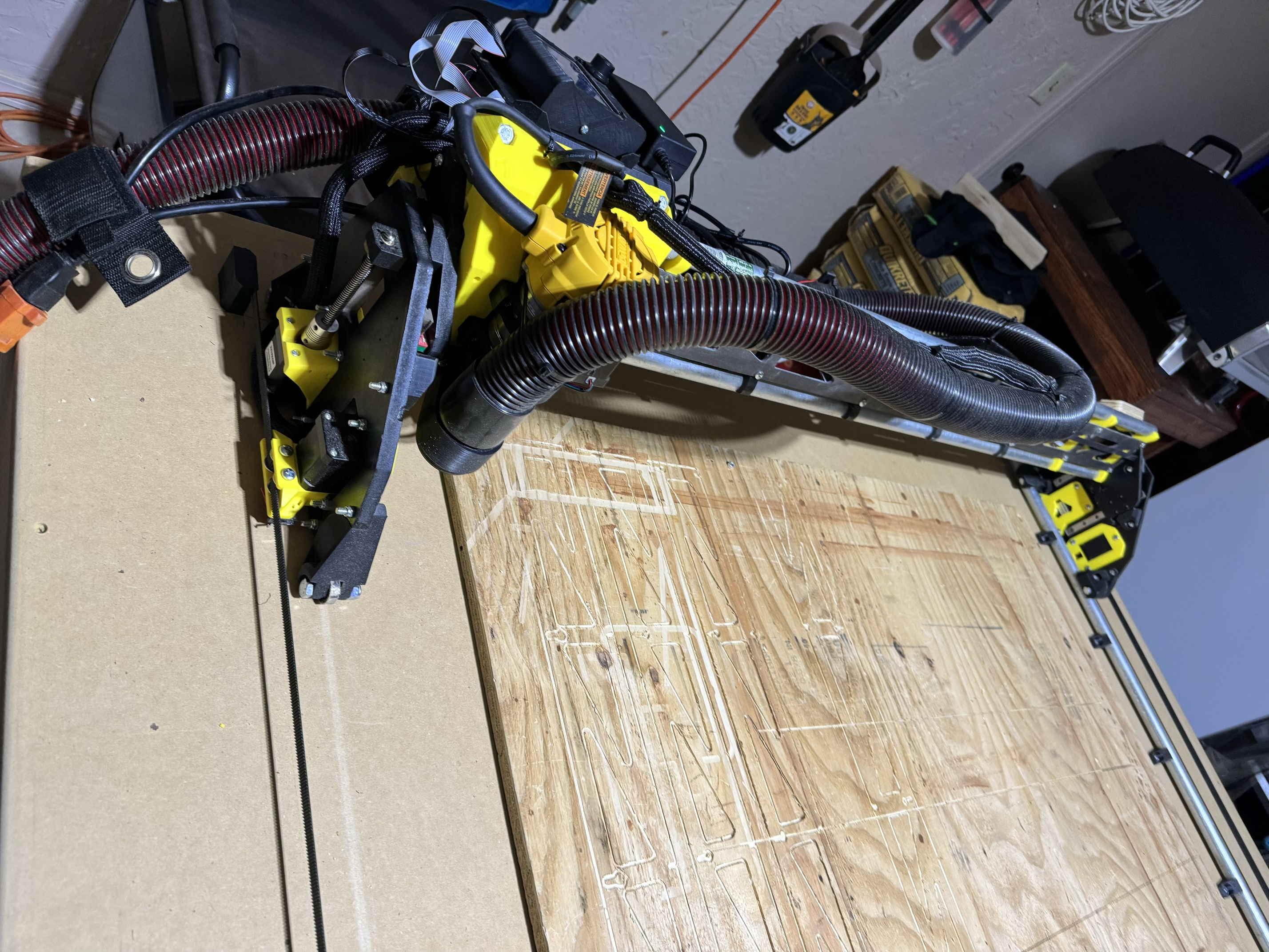
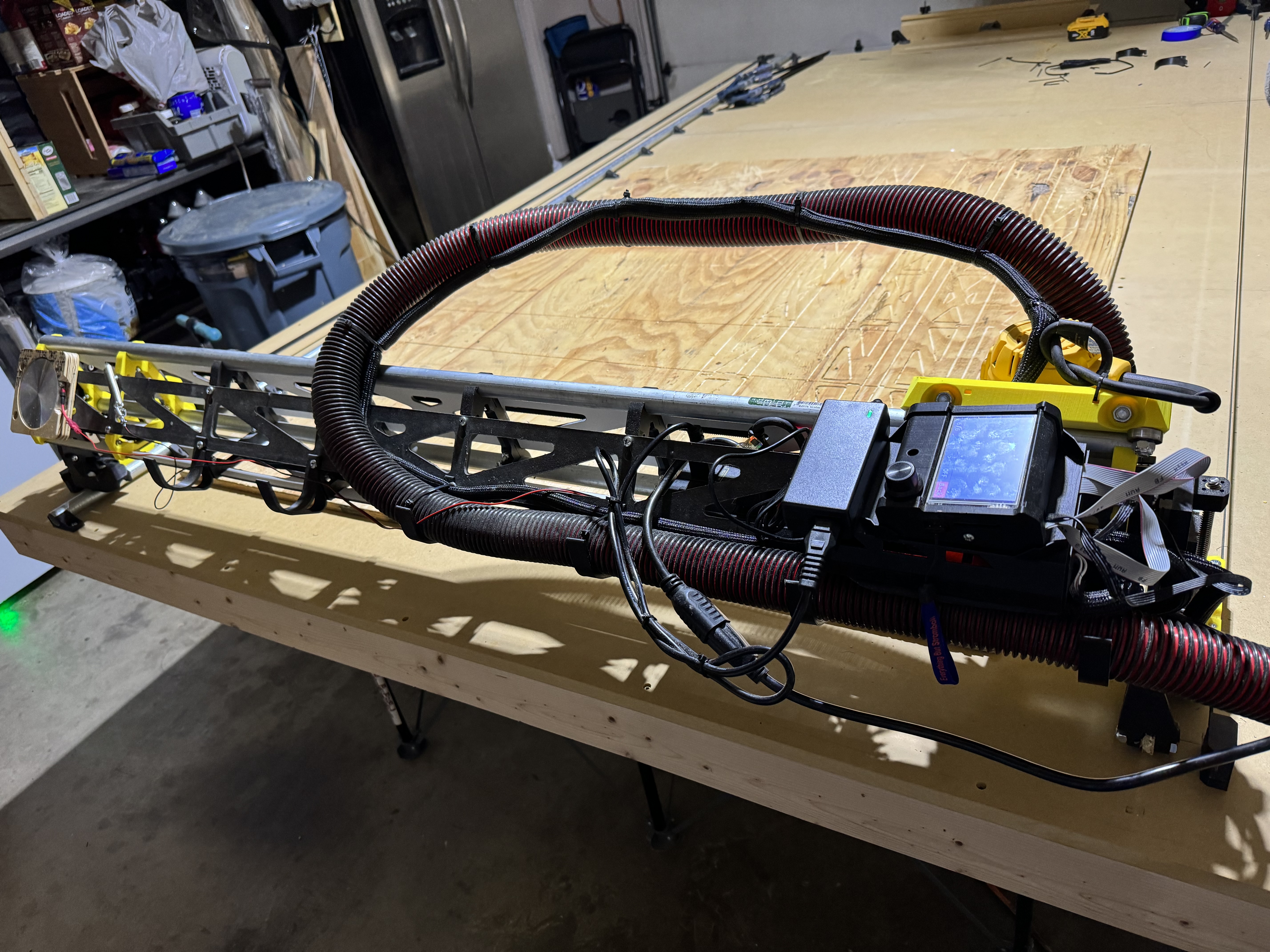
As you can see, it’s alive! At least for the purposes of clearing a test pocket.

The one thing I can’t figure out is the M0 messaging. I spent a lot of time working on the configuration of the post processor to make sure I could give myself useful instructions at the TFT screen instead of having to remember all the parameters like the work piece minimum size, orientation and desired milling tool.

; *** START begin ***
; Set Absolute Positioning
; Units = mm
; Disable stepper timeout
; Set current position to 0,0,0
G90
G21
M84 S0
G92 X0 Y0 Z0
; COMMAND_TOOL_MEASURE
; Probe to Zero Z
; Ask User to Attach the Z Probe
; Do Probing
; Set Z to probe thickness: Z0.5
; Retract the tool to 20
; Ask User to Remove the Z Probe
M0 Load tool: 1/4" Flat End Mill and attach ZProbe
G38.2 F100 Z-50
G92 Z0.5
G0 Z20 F300
M400
M0 Detach ZProbe
; *** START end ***
;
; *** SECTION begin ***
; X Min: 83.197 - X Max: 551.806
; Y Min: 233.39 - Y Max: 484.525
; Z Min: -19.05 - Z Max: 15
; Table Pockets - Milling - Tool: 11 - flat end mill
; COMMAND_START_SPINDLE
; COMMAND_SPINDLE_CLOCKWISE
M106
; COMMAND_COOLANT_ON
; >>> WARNING: No matching Coolant channel : Air requested
M117 Table Pockets
; MOVEMENT_CUTTING

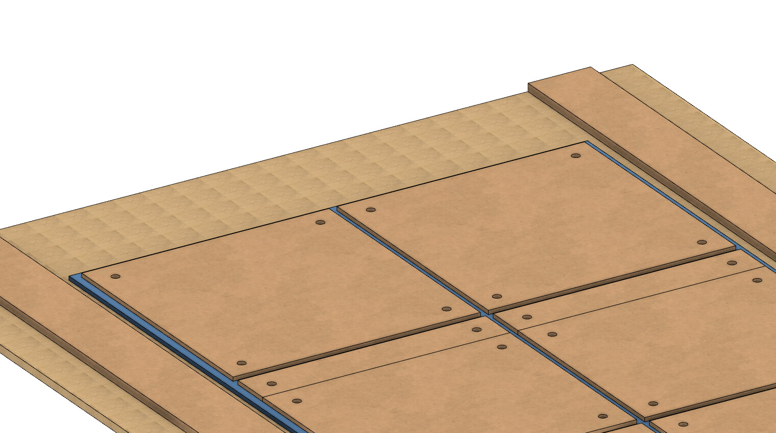
Instead, all I get is a pause screen and a resume button that really gives me no instruction. If I didn’t know a Z-probe action was the first thing it was supposed to do, I would have no clue until it started slowly dropping the Z-axis or kicked on the router…. I’ve heard Marlin mode or an M117 lcd message might be the right direction and I guess that’s up next once I get my start plates cut and installed.

1 Like

Looking good! Great job!

I dont see what you’re using for electronics, but the M0 should work for Marlin firmware with the 12864 full graphic controller (Or the TFT35 in Marlin mode.) I do not think it works as expected in touch screen mode, and not with the Jackpot controller, so far as I know.

So you may need to mess with other message gcodes. I don’t like starting the code with touch plates, because I’ve made too many mistakes. A touch plate not flat to the work reads too high, or not properly under the bit, too low. I’ve had wire problems, and accidental contact with the bit… then the program wants to go ahead, and Ive got to abort and restart. (Even worse when it’s a tool change, and re-start isn’t a good option.)

Did you add parameters after the M106? By default, that only works the “tool” fan, typically the part cooling fan for a 3D printer, and handles PWM control, but should be usable for other fans as well. (Top of my head, I only know RepRap Firmware syntax, so I’d need to look it up.)

1 Like

I’m using an SKR Pro and the TFT35. Didn’t know about Marlin mode until a few days ago and haven’t had a chance to test it yet. I’ll set the machine back up this weekend in Marlin mode and hopefully it gives me my intended messaging and pause options and I can move forward from there.

On the Z-axis touch plate, I like the idea more than I like the experience of using of my touch plate so far. I have big hands and trying to get under the router to connect that clip was a royal pain and I ended up moving the router and gantry half the time, messing up my zero positioning. My solution to that was to clip the wire to a conductive magnet and then just stick the magnet to the collet nut and then we’re good to go. The plate itself is also a problem child insofar as all of your reasons lol… I’ve not had it perfectly flat… I’ve had to become a contortionist to be able to hold the plate down and bend around the table to look and make sure it’s positioned properly… I’ve accidentally touched the collet nut, exposed metal of the clip connection and the bit itself… I think the short length and low weight of the plate might be my issue here and I might going to look into obtaining a commercial touch plate with some heft to it.

I tried adding specific fan and speed parameters when testing M106, but none of it worked for me. I didn’t want to worry about messing with the default firmware, so I just hooked up to Fan0 since the meter said I was getting live voltage when I sent the M106 command.

I’m finally got around to a little cable management and added a bit of a z-axis probe upgrade.

I added cable loom to all the major runs and re-ran the cabling through the center of the gantry and moved the IoT switch into that space as well. I found out my handwriting sucks horribly when I re-connected the stepper motor cables and mixed up the E0 and E1 connections… that was fun to watch…

For the z-probe upgrade, I used a 100mm diameter 10mm thickness aluminum plate and a bar magnet to made the z-probe attachment and removal much smoother. Then I added a mount on the far side of the gantry to keep the wire off the table and stuck the magnet to a screw. I’m hoping to update it to a full 3 axis probe at some point by milling out a corner underneath and adjusting for the height difference.

Still a little work to do on a couple power cables at the back, but that’s enough for one day…

Anyone have any good ideas on how to improve the efficiency of the dust shoe? I’m getting a lot of air movement, but not a lot of wood chip and dust removal…

1 Like

Perhaps consider my floating Z dust shoe mod…

https://www.printables.com/model/625802-new-for-3-makes-of-routers-lowrider-v3-floating-z-

You can also try my improved dust shoe with TPU bristles. :slightly_smiling_face: Works great and is not a complicated mod.

1 Like

I took a look and I like that direction.

I’ll start printing those parts as soon as my SKR Pro enclosure replacement finishes.

Where can I purchase some 2.4mm EVA foam? I see a lot of round numbers on Amazon, but no 2.4.

Sure. In my original posting of version 1.0, I showed links to all the items I used. Here’s the Amazon link for the EVA craft foam:

12" x 18" EVA craft foam

Apparently I failed to include the purchase links a 2nd time when I posted v1.1, so I just now fixed that. I added the following to the revised version:

Here are links to key parts/materials: 12" x 18" craft foam, a 2.5" flex hose (of which only about 110 mm or so is needed for this), some 2-1/2 Inch Key Hose Clamps (two of them to attach the hose), and a 100mm MGN12 linear guide with MGN12H bearing slide block*.

Let’s go, Amazon! How are you slower than my 3D Printer?! I blame Christmas.

Also… I have a new idea since I’m getting annoyed at repeatedly screwing or bard nailing things into my spoilboard and having to deal with the after-effects…

I went with a piece of plywood for now for my spoilboard, but I’m thinking about moving to CNC-cut 2x2 foot replaceable squares with threaded inserts in the table between permanent T-Track segments, something like this:

While I love the capacity to cut full 4x8 sheets, I noticed that after I build the LR3, I don’t actually use that full capacity that much yet, so I’ve noticed that I cut into the spoil board at the head of the table far more than at the foot. So with the 2x2 spoilboard segments, I can just replace the pieces I need. Here’s a closer look at the idea.

With my table build, it makes the job a little more complicated as the 6x10 table splits into three 6’ x 40" sections for storage so my car can live in the garage. So 4 of the 2x2 squares will end up being split into basically 24x20" and 24x4" pieces.

I also noticed that with the LR3 positioned on the table, the spoil board height added to the work piece height left very little vertical capacity left to get my hands underneath to change bits and whatnot. I believe the Z-axis for the default LR3 build only has about 80mm of vertical movement, so the spoil board takes up roughly 25% of that already, then add the work piece and my bit is stuck and I can’t get it out if I do a programmed tool change. So I’m thinking about adding 6" runners down the entire length of the table to lift the LR3 hardware mounts to the same height as the spoil board to give me that space back.

Please someone poke some holes in my idea before I go buy a bunch of T-Track and MDF…

2 Likes

Sounds like a plan! Keep us updated!

I also built my table so I could replace portions of the spoil board. The main concern I’ve had with that design is that I surface my spoil board to ensure it is flat. If I switch one tile, I end up having to surface the whole spoilboard again, or I end up with a slightly uneven surface. My machine is smaller, but I have 3 tiles, and ultimately, they’re all pretty much the same thickness, Not sure it’s going to save me on spoilboard material as much as I had hoped. FWIW.

I built my table so that the wheels are level with the intended spoilboard. That gives me the most accommodation for material. Also note, the lower ths machine is, the more stable. So the closer it can be to the bottom, the better.

All that said, I also have 50mm of extra Z on my LR3.

Amazon came through before the New Year! I’ll work on installing tomorrow and we’ll see how she goes.

@DougJoseph
Did you still need feedback on the Dewalt parts?

1 Like

I’ve had some parallel thoughts - although I’ve just divided the table into three parts. You might be interested in my “hold down” thoughts - to enable you to flip the boards over as well.

another development on the same line - you can make custom hold down parts just in one or two sections if you wish, so that you can make your tee tracks on your machine to suit rather than using the commercial ones.

I should note that at the moment, while I’m doing other things - the boards are in three sections but no fancy hold downs yet!