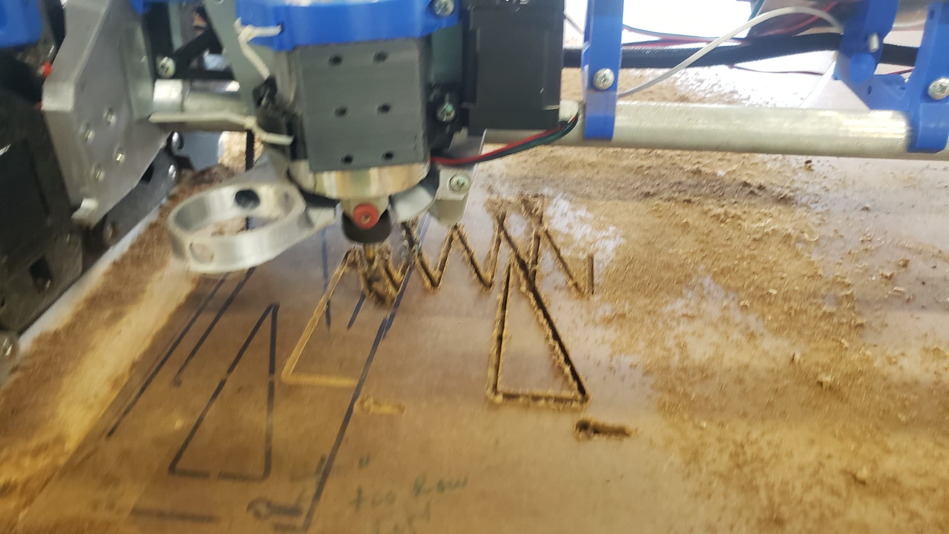
So I finally got the router mounted. Did some testing with a pen and everything seemed to draw correctly. Then I went to estlcam and prepared a deeper cut program. First try everything seemed fine but then updated it with tabs and correct depth. Now the cut seems like it’s getting lost. I used automatic tabs cuts and the new lines seem to be doing this where the tabs are.
I would start by taking the auto tabs off, I have never used it so I can’t be sure it works as it should. When you do it manually you can control the depth, and the clearance height.
Hello and welcome. There is a lot to learn and you’re on the intense training track.
My first impression when looking at your results is that there is a lot of burning. It is possible your first bit overheated, lost its hardness, got dull, and then the subsequent cuts had way higher loads and the machine went bonkers.
You can test this theory by trying some or all of the original gcode with the old bit (if it works, something is wrong with your new gcode). Try a new bit with the new gcode. If that works, it is your old bit.
If you can slow down the spindle, that should help with the burning. But also make sure you have bits that are made to cut sideways (CMC bits are, drill bits are not).
I can’t tell what spindle you have. A long time ago, the complaints about the aliexpress spindles was they had a lot of runout. I haven’t seen that in a while though. Runout would cause the bit to wander, but it would mostly stay on track. Your pattern looks like skipped steps.
I got the grubs. Dialed in yesterday, leveled to within a millimeter (I’ll adjust table and level soon when I have the time). The problem doesn’t seem to be the machine itself, or to Jeff’s point the bit, which is pretty much new and running on soft material. I do think it’s a programming issue, but can’t see why that would happen with cam showing the correct paths. The keyhole cut perfectly. It was only the end of the second path it decided, nope, I’m going that way.
Back to estlcam to try a new program, will update when I see some results. Still would love to see your updated touchscreen firmware become official!
Jeff I do want to apologize for brushing off your suggestion. While I was using a small vbit for this cut, I wasn’t worried. However in the meantime I got commissioned a job using my little 4040 where I needed to clear a lot of material. Nearly started a fire with a fairly “sharp” mill I had. Got myself and upcut Freud bit on amazon, then I breezed through the pieces at lower rpm and faster feed. But, alas, this was not the issue for this particular case!
As an update, I have done quite a bit of troubleshooting. I really couldn’t figure it out, because I literally just realigned the gear cogs on the belts/steppers. Somehow, even after forcefully tightening, the grub screws on both my x and y2 were loose/gone. I have no idea what happened to them, I just tightened them. I ordered new belt cogs, and should arrive this evening.
In the meantime I realigned almost everything. The rail is within half mm/ over 1.8m. Adjusted Y endstops to be within about .4 mm, and I am futzing with the X/Z gantry and lead screws to get that aligned, which it is not. Since I am building this for wood and plastic, I have some decent tolerances, and tramming is always going to be needed. Once those grubs are in, I think we will be flying through some material.
Just by the by, this all started when needing a bigger cnc. Some dude on marketplace selling a used lowrider 2, in pieces for $100. Four 3d printers later, and replacing almost every part anyway, I am nearly ready to start cutting 4x8 on about a $600 budget.
Happy to report it’s square within a mm on the diagonal!
Now, x/z is off (no change there). It’s likely due to tension of belts and the thinner wood I have as the base. Maybe level. Maybe something else, like the y/z plates. I looked, but couldn’t find, a thread on adjusting these?
You can adjust the XY and XZ with M666. The touchplate will help you level your Z axis, basic instructions at the end of the build instructions. You can also use those instructions for XY (I have a little YouTube video showing my XY test for getting well under a mm over 4’x2’).
Got a lot done this week. Cur struts, wish I’d have gone q bit deeper to make them release easier and look cleaner but I’ll redo that someday in the future.
Didn’t have any patience for the pen mount so here’s my crown in router form.
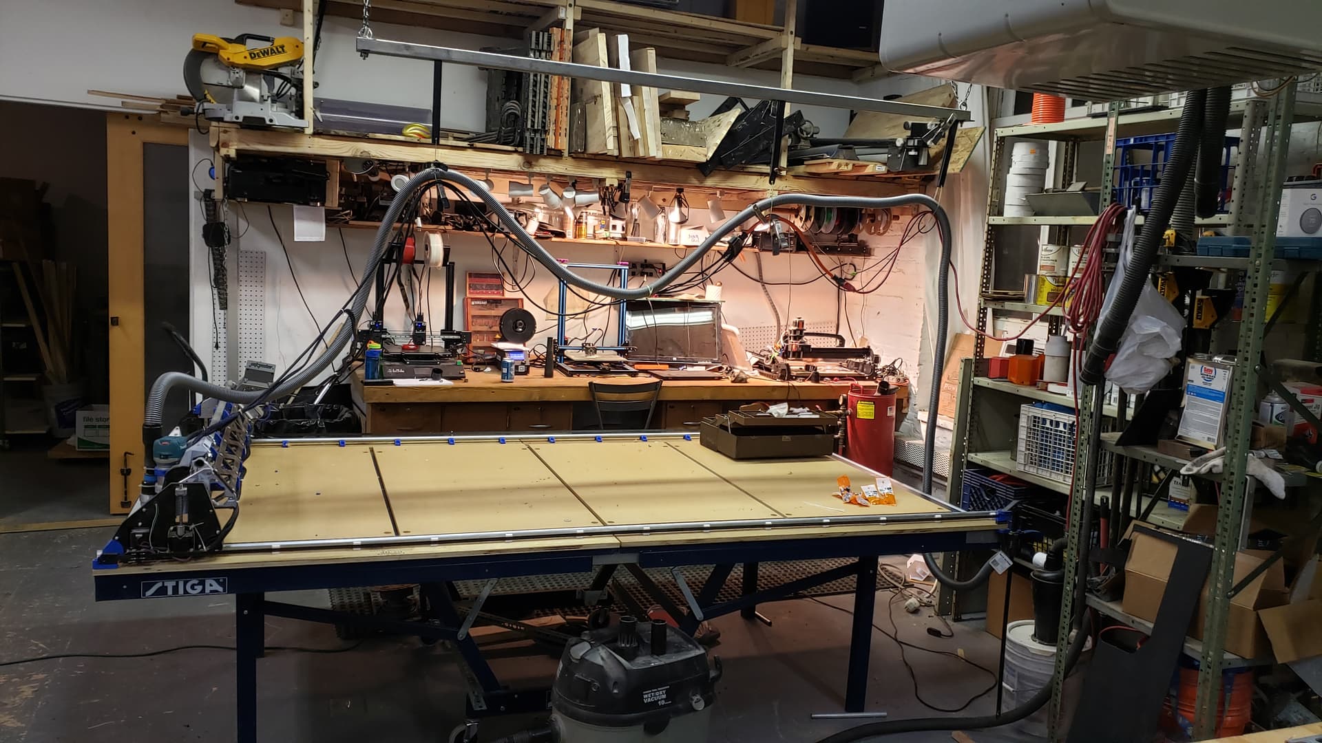
I also got a championship stiga ping pong table with a heavy duty 1" thick mdf table top ill eventually mount it all to. $50. It’s a beast and should do the job, now I just need more space…
Doug, plan on using your floating z dust shoe. Tramming was quite dusty, though my pass was probably way deeper than it should have been with a 25mm flattening bit.
Today cracked my core trying to shim the router to tram correctly, currently printing a replacement. Seems to be off .5mm or so front lower than back (-y to +y). I rounded out a nut hole so it was going to happen anyway.
Has there been any updated instructions on how to tram the router itself? I was going through and tightening/loosening anything I could think of, but to no avail. Shimming was an option, but wondering if anyone has found a good solution/instruction on how to do so. I’ve found a few forum posts but nothing past a few responses.
There is a forum thread where someone devised a rather ingenious way to tram the router with an eccentric ring approach inside the motor mount. If I can find a link I will paste it here.
Blue tape is what I always use. My current mount has 2-3 layers about 2" long at the 10-11 o’clock position. With my printed tram tester that is as perfect as I can get it.
The adjustable mount is amazing, it does kick the router out a few extra mm though.
As it is in Printables, it will kick it out between 1-2mm depending on the adjustment.
I didn’t put it in the Printables, but I also played with one that had more adjustment range, and if no adjustment was needed, it didn’t kick it out at all. There was 0 shim on the back side.