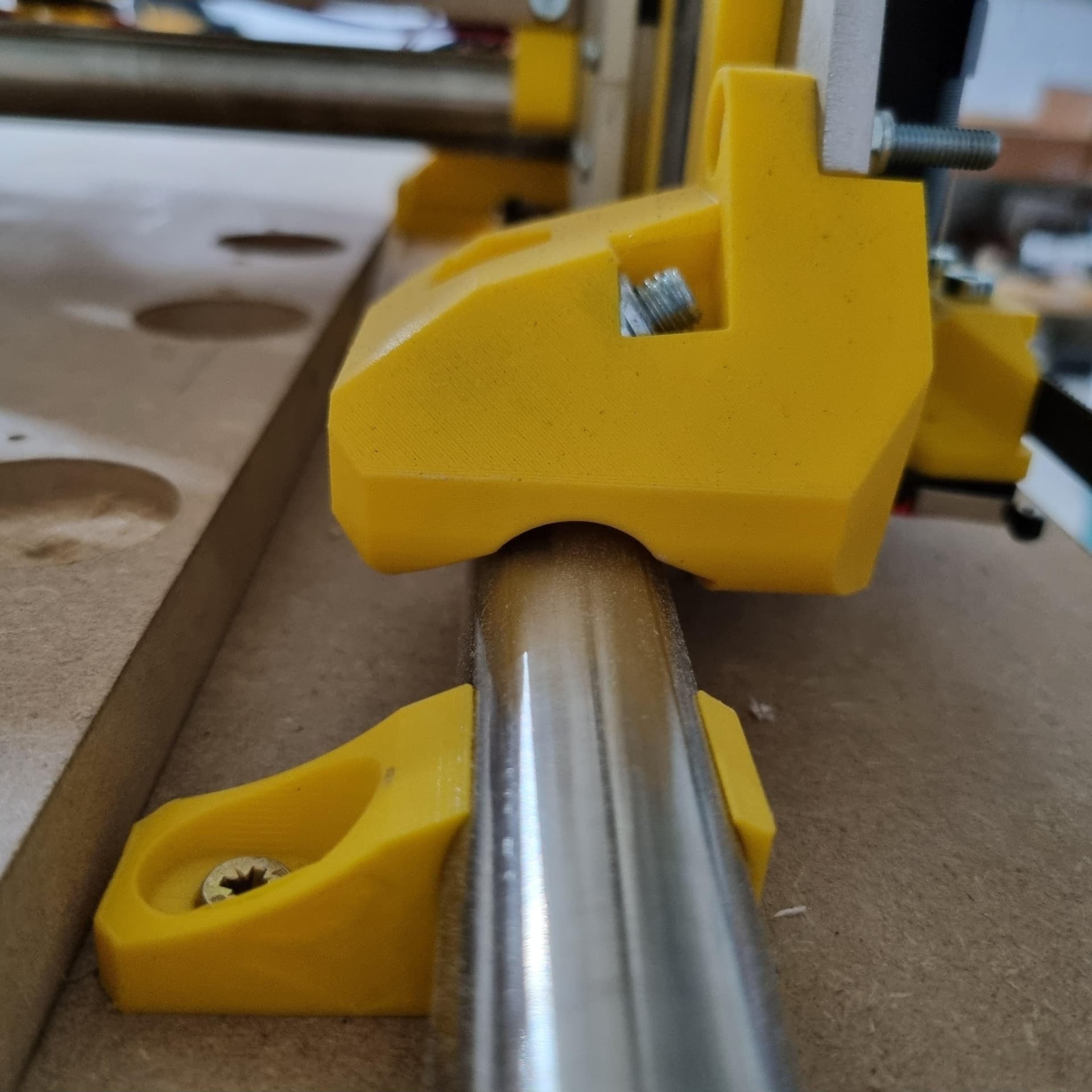
I noticed my front rail roller has an issue. When looking up close I do notice only 1 bearing touches the rail after homing.
It stays that way when travelling all the way to the end of the table. However when putting the machine in use (so there´s some load) both bearings seem to touch the rail.
In one case I noticed that when the front bearings touch, the issue is at the rear rail roller (but that was just one time only).
I´ve already reprinted the part to check if this is the cause, but it isn´t.
My table is as flat as it can be,
and the 25mm rail is -as far as the eye can see- well attached using the clamps.
The side plates are made out of 6mm Alu, and they are flat too.
The Y axis is squared.
So I am a bit confused on how to fix this. Any suggestions?
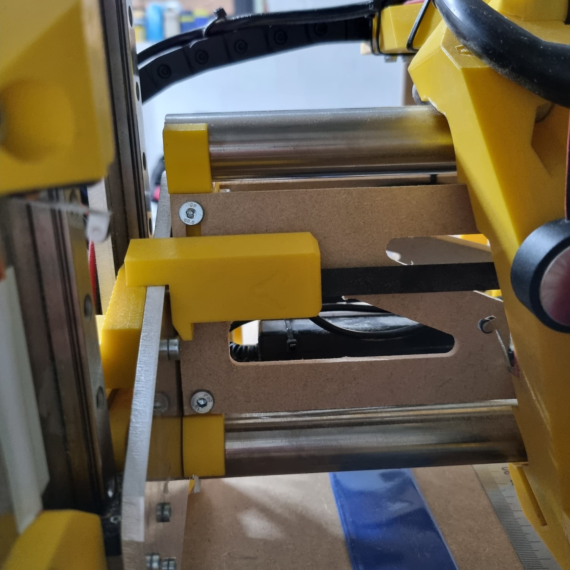
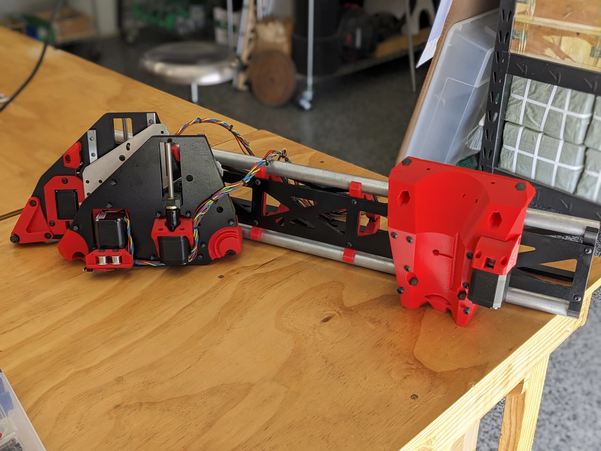
Tried to take a picture, obviously that didn´t work due to the angle
In any case here is the picture.
Noticed some of my LR3 roller bearings lift off the Y rail when the belt holder blocks were not squared up and/or correctly spaced from the Y rail. I use the Y rail as a reference from which everything else is spaced/aligned. The lift was so subtle, and bearings are tucked in deep enough, that I didn’t realize lift was happening for a while.
Can you measure the “toe and heel” distances of the trucks? If the toes are farther than the heels, it will pull up like that. I had something like that and traced it to a bad printed part, and fixed it with some shims cut from yogurt cups.
Honestly thought I’d measured diagonals and setup correctly at first, but my framing square and drywall T square set me straight, literally.
Only noticed roller bearings not making consistent full contact while trying to troubleshoot why I wasn’t able to cut truly square panels for my MP3DP where I needed < 1mm accuracy.
Was also troubleshooting why Z at Xmin and Z at Xmax were off by 2mm. Root cause for that was my endstops triggering at different heights. Fixed via mix of physically bending the end stop metal swing arms, and, using M666 to calibrate endstop offsets.
Captured some details about what I was seeing regarding the roller bearings going off piste… Was ~2mths ago though, happy to dig into my notes and share more details if it’s relevant to your problem and might help. Let me know, cheers!
So the belt seems to be ok although it could move like a mm to a better position. But when I wiggle the upper part of the beltholder I notice that the 2 part design is the cause for this. I have printed the solid replacer from printables but have yet to find time to install this one.
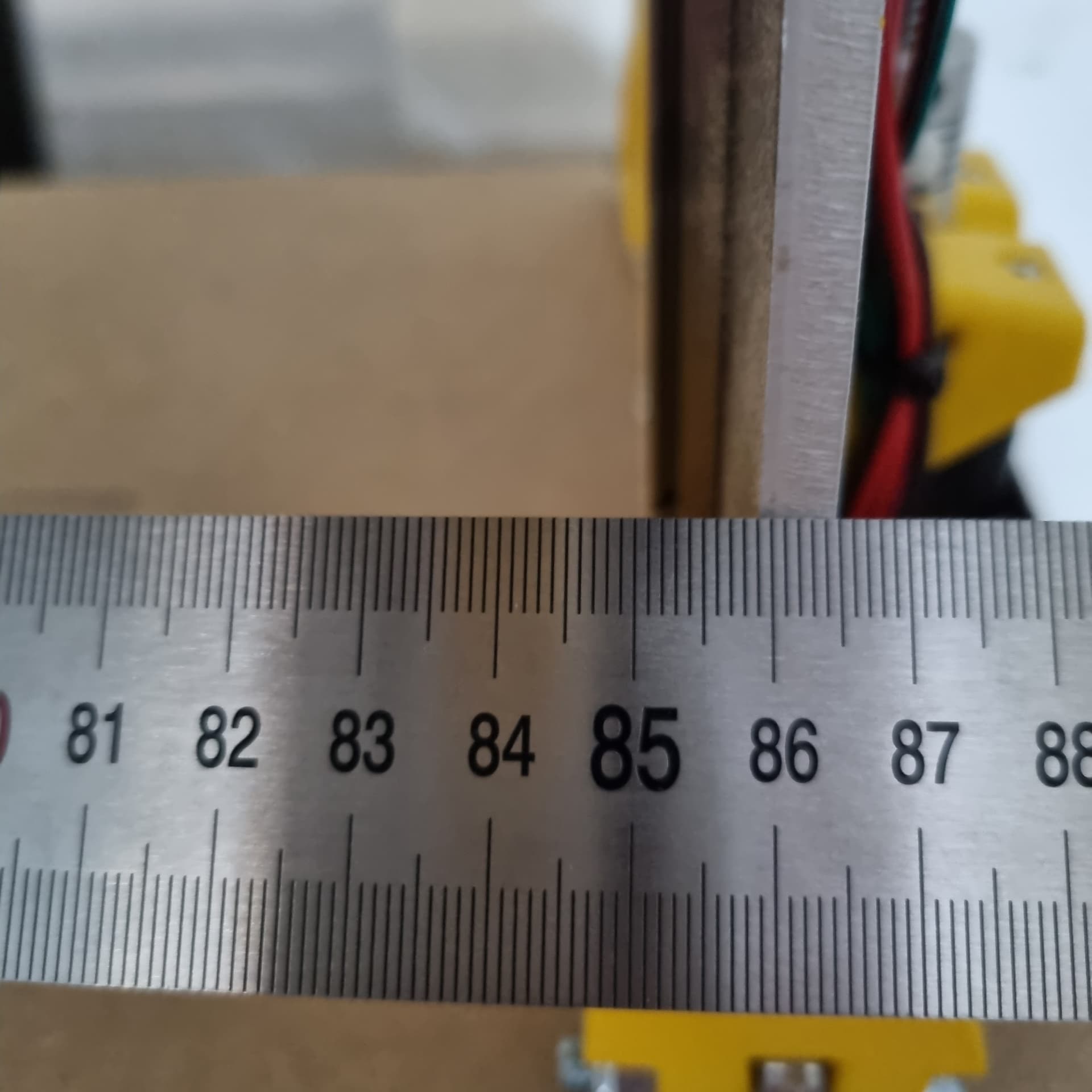
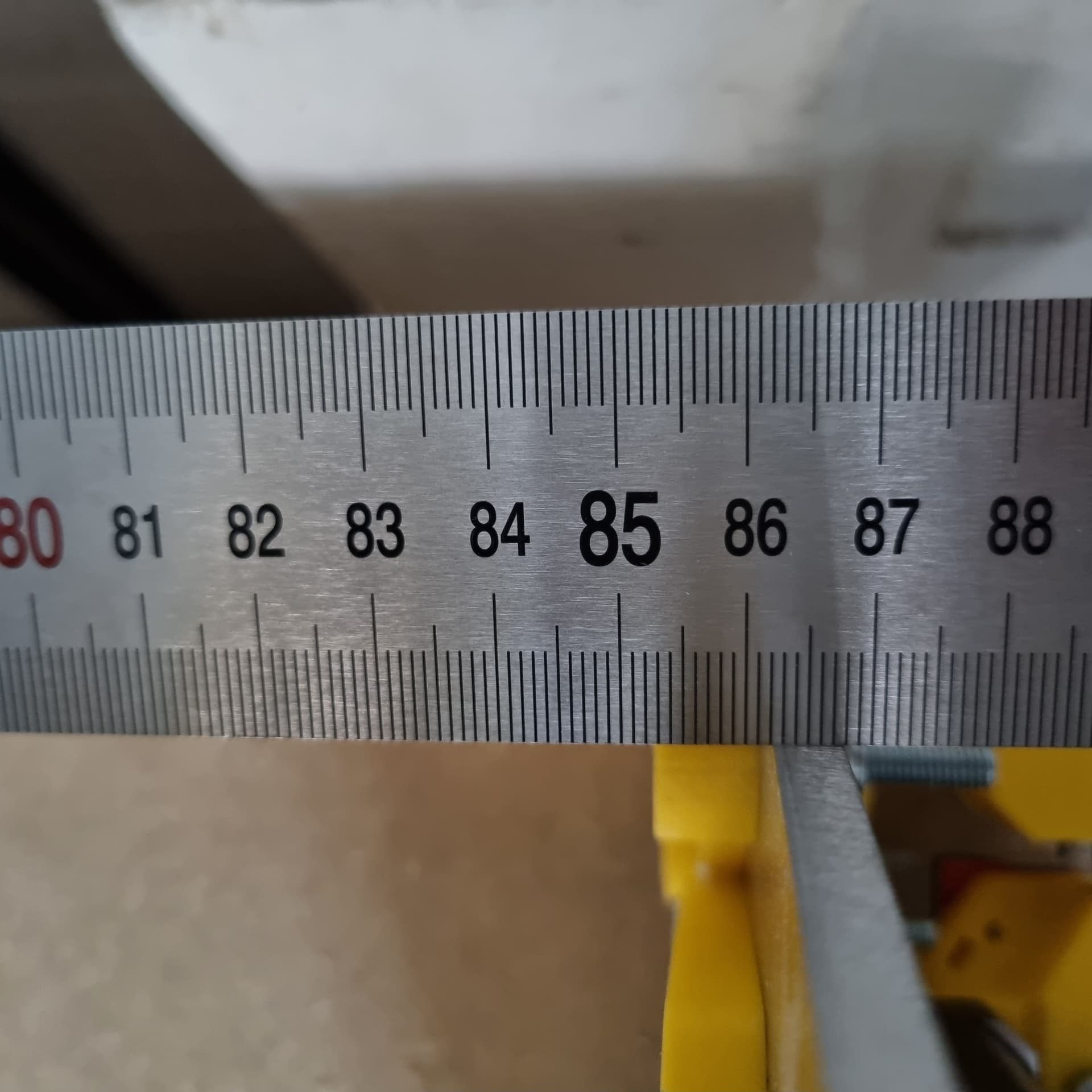
Now when I measure “toe & heels” it seems that this might be the cause of the bearing lift. Let me show numbers:)
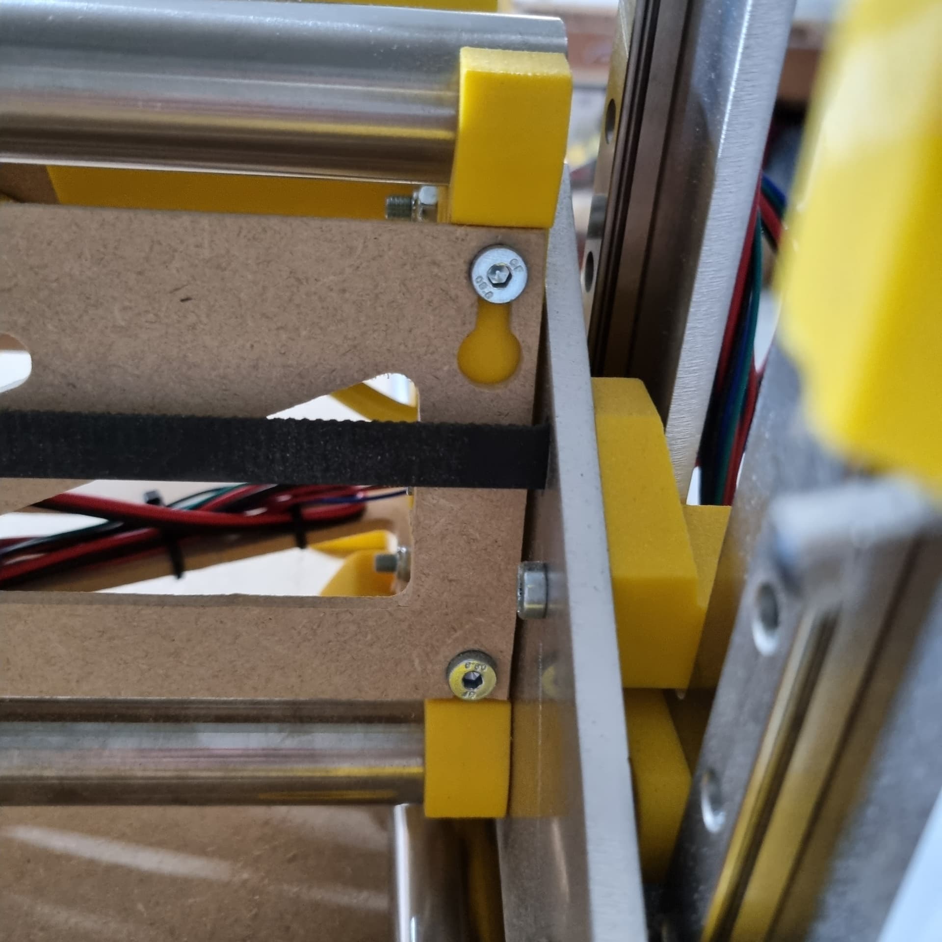
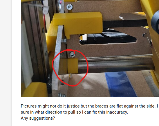
Pictures might not do it justice but the braces are flat against the side. I could loosen the tubes but not sure in what direction to pull so I can fix this inaccuracy.
Any suggestions?
Toe and Heel have 3mm difference? What gantry parts are touching the XZ plate, just the printed braces hopefully?
Think XZ plates are expected to be in full contact with the printed end braces. However, Tubes and Struts are expected to be flush with the braces, or just short even. Have seen forum posts where tubes being proud/too-long caused toe and heel distances to not match, causing other problems…
If only the braces are in full contact (a good thing), then, am wondering what thing(s) are causing the 3mm diff… Are the struts square, and measuring to be exactly the same length? Are the Strut bolt diameters tightly fitting the Strut holes/notches, or do they have large enough gap/play that you need to square up the end braces perpendicular to the Strut plates when snugging up Strut bolts?
That’s correct. If I would tighten more I would just end up crushing the PLA (don’t ask me how I know )
The tubes have been cut to exactly the same size. The struts are exactly 82cm as what was needed for my table.
Regarding;
I will need to check, it’s been a while. If I remember well I first installed all braces and afterwards fitted the struts. I think it was just a tight fit.
Not looking forward to dismantle those, but it seem to be the way forward, so will make time for it.
Your X rails need to be slightly shorter than your beam by a mm or two. It looks like you are about 4mm too long and the rail is hitting before your brace. On your pictures both sides look like this.
it will be some optical illusion, in reality, the rail is flush against the siding on both sides (at least at the bottom side, the upper is shift 1mm more to the side but that shouldn´t be an issue I think).
Both the strut & rail are 820mm long. So what you are saying is that I should add some space on both sides of 1-2 mm?
Tried to fix it today, not going to hide it, but got frustrated doing so
I removed the struts, refitted everything multiple times, and now I am exactly back at the beginning :@ with the same deviations. To make things even worse I ruined the strut because I overtightened it.
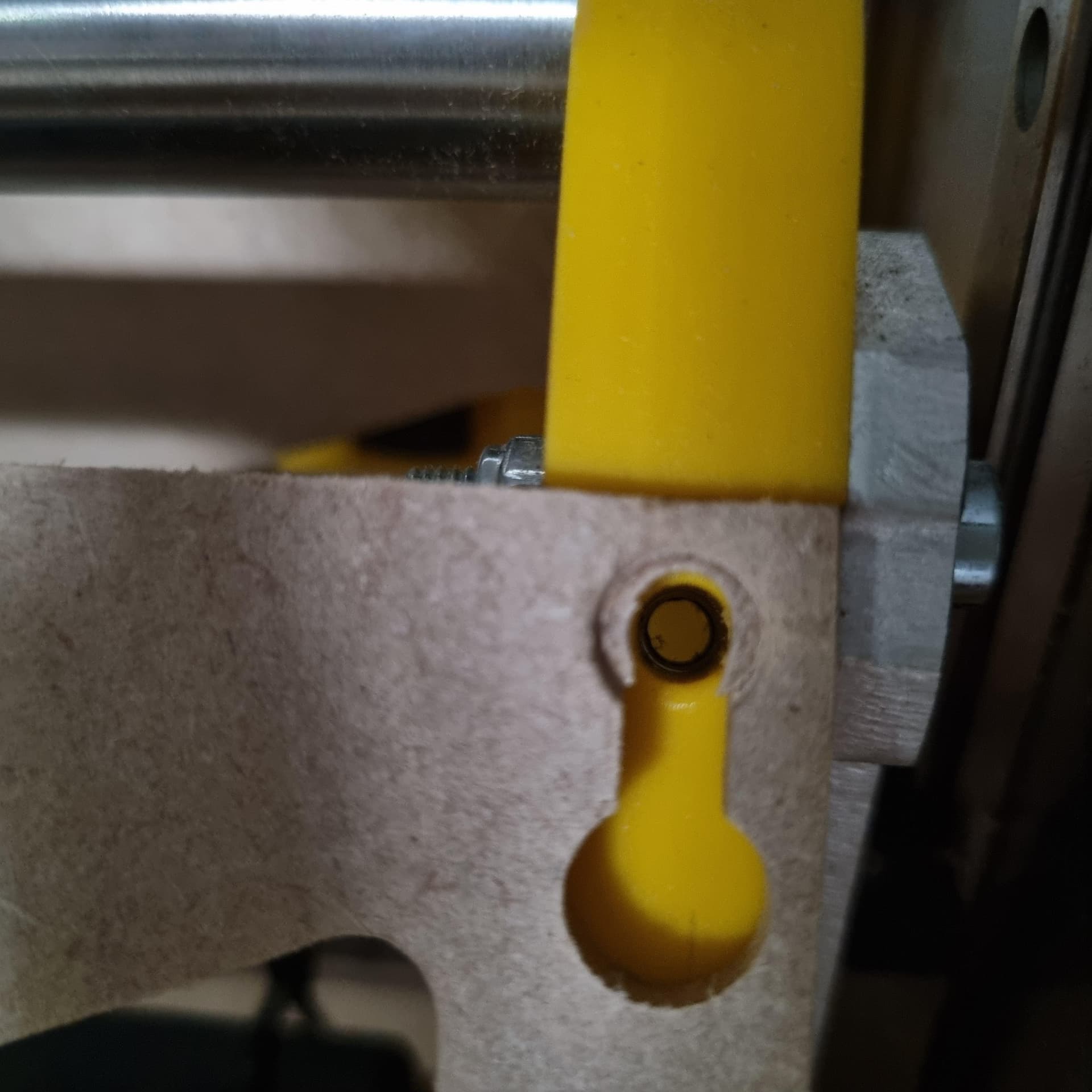
This is how the strut holes looked like. So I believe that was ok.
Since I will need new struts I will make them again in 3mm Alu, suspect that wont be an issue considering weight.
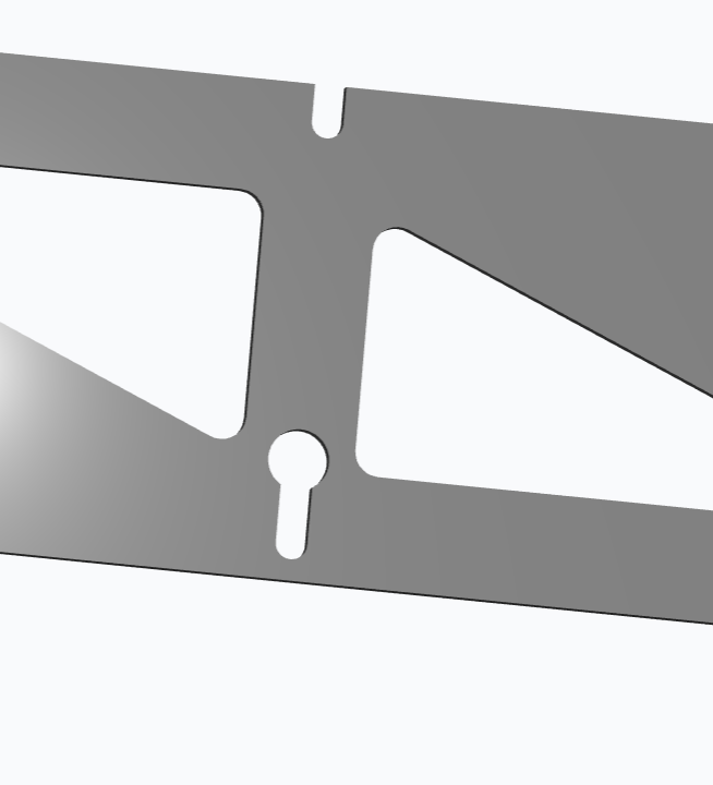
One thing I can´t find immediately though, do I cut on the insight of the lines ? At least that is how I did it before. The outerside on the outer side, and the rest on the inside of the line.
If you are going to do it in aluminum, you might as well just cut the holes and not use slots and keyholes. makes for a real nice strong fit up. I don’t think you should remake them though. Keep looking for the mystery angle.
Yes. The centers are marked and easy to drill in CAM instead of cutting teh slots and keyholes. Then you can easily trace the outer shape and cut the rectangle. Have a look at my latest build for RMRRF.