FluidNC + 0–10 V Spindle Module: Spindle Always Runs at Constant Speed

Hi everyone,

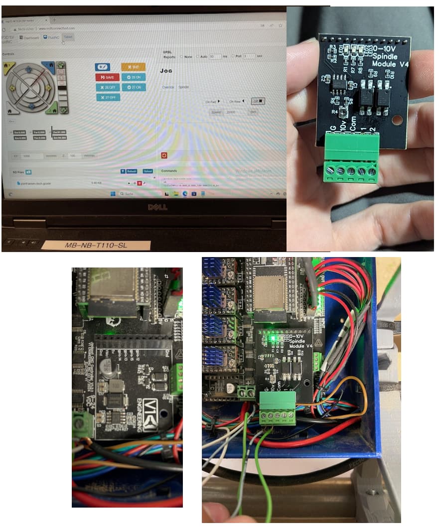
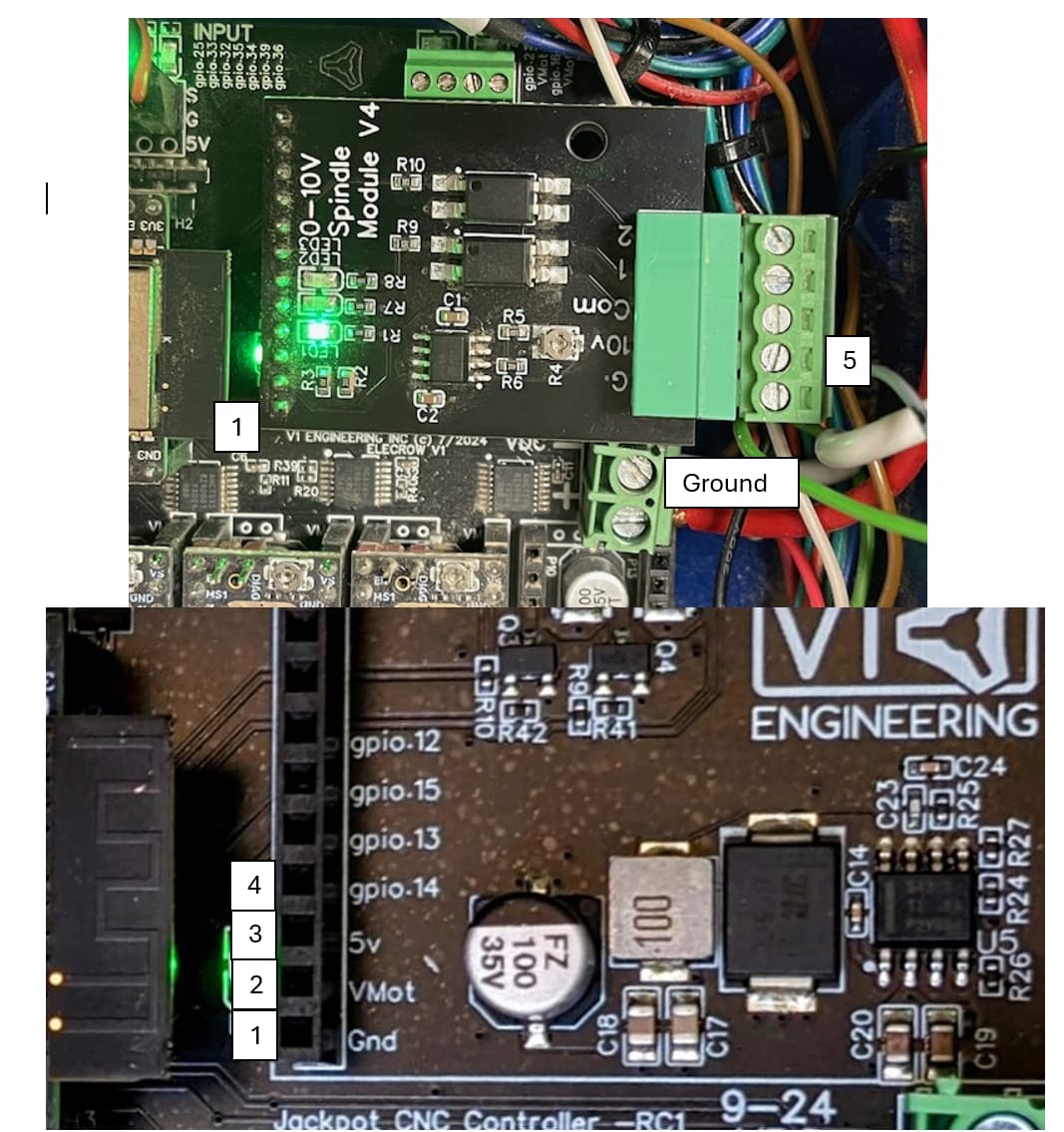
I’m using a V1 Engineering control board along a 0–10 V spindle module (see attached image top right), and I’m trying to control my spindle speed via FluidNC. Unfortunately, I can’t get it to work correctly.

No matter what I set in the FluidNC Dashboard (see attached top left), the spindle always runs at a constant speed. I’ve connected the 0–10 V output from the spindle module to the speed control input of my spindle (see image buttom right), and I’m expecting the speed to change according to the S-value.

Also at the spindle module, a wire is connected to the G terminal, which is tied to Ground of both the spindle and the control board.

Here’s the code I added to my FluidNC config file for the spindle:

yaml

pwm:
  pwm_hz: 5000
  output_pin: gpio.14
  enable_pin: NO_PIN
  disable_with_s0: false
  s0_with_disable: true
  spinup_ms: 0
  spindown_ms: 0
  tool_num: 0
  speed_map: 0=0.000% 1000=100.000%
  off_on_alarm: false

Any ideas on what might be going wrong? Thanks in advance!

Which VFD do you have? Did you look at the VFD instructions to enable the 0-10v mode?

1 Like

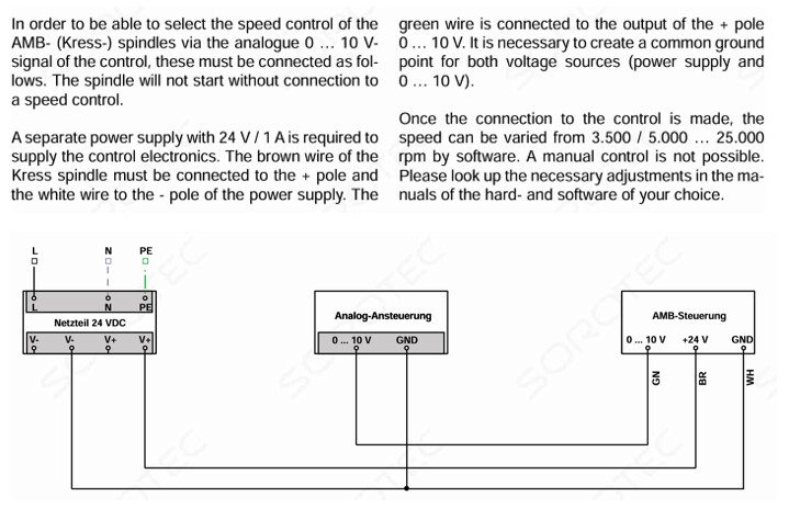
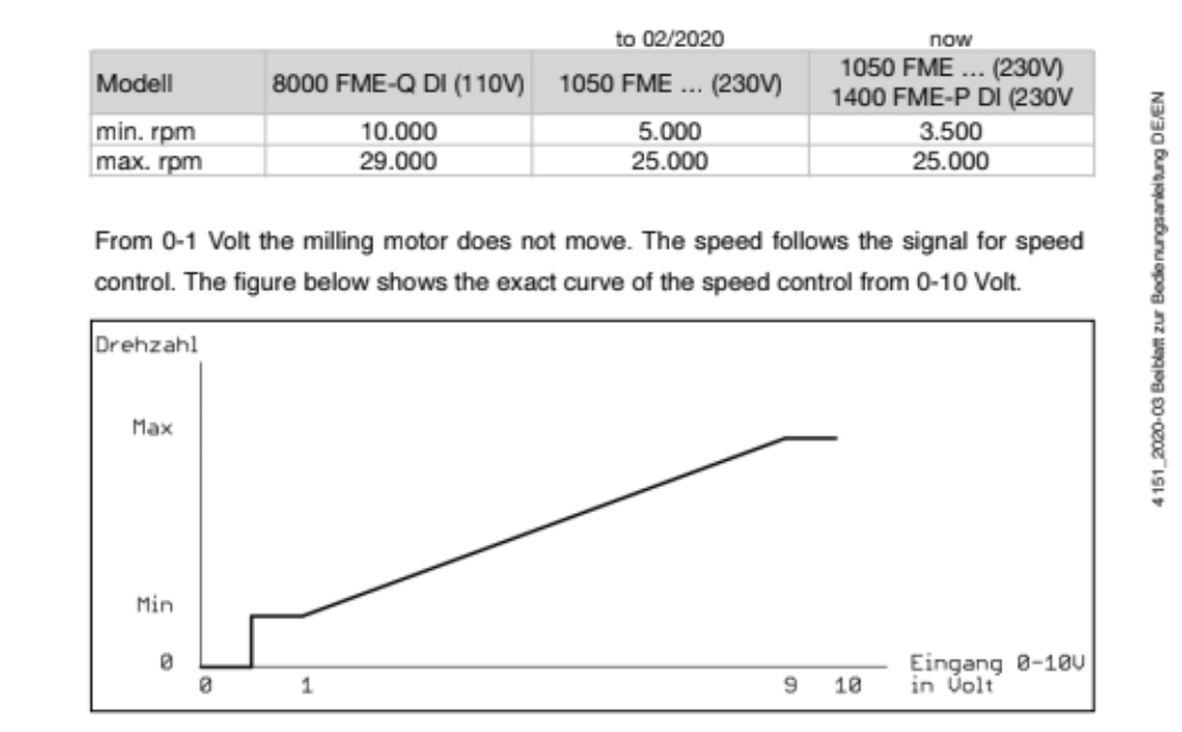
Thanks for the reply! I don’t use a separate VFD — my spindle is an AMB 1050 FME-P DI, which has a built-in speed controller. According to the official documentation (see attached image), this model is specifically designed to be controlled via a 0–10 V analog signal.

The + and – terminals of the 24 V power supply of the spindel speed controll are connected to the V1 Engineering board, so the control logic and the spindle controller share a common power and ground reference

Looking at the examples, I’m guessing the speed map needs to be adjusted. You’ll notice the example speed map goes from 0 to 24000 and 6000 is still mapped to 0.

1 Like

Thanks a lot for the hint — that makes sense!

I’ll try adjusting the speed map accordingly. I won’t be able to test it until tomorrow, but as soon as I get to the machine, I’ll give it a go and report back.

Really appreciate the support!

Based on this PDF I found, I think you want:

speed_map: 0=0.000% 3500=10.000% 25000=90.000% 25000=100.000%

Or something like that. I don’t have a spindle so I’m not sure.

3 Likes

Just a quick update: the code I posted earlier was outdated — I had already uploaded a version with the adjusted speed map to the controller. Unfortunately, changing the speed map didn’t solve the issue; the spindle still runs at a constant speed regardless of the S-value.

Put a DMM in voltage mode. Connect the (-) lead to the GND terminal of the AMB. Turn on the system and let it boot. Measure and report the voltage with the (+) lead connected to the following points:

  • AMB +24V
  • AMB 0-10V
  • Jackpot VMOT (-)
  • Jackpot VMOT (+)
  • Jackpot 0-10V module COM
  • Jackpot 0-10V module 10V
  • Jackpot 0-10V module G

In FluidNC, command full speed on the spindle, repeat the measurements on the 0-10V module.
In FluidNC, command the spindle off. Repeat the measurements on the 0-10V module.

Report all measurements.

Some suggestions-

  • not the problem, but best practice is to twist the two wires going from 0-10V module to the spindle.
  • The wires going to the spindle look like solid wire. Best practice for wiring a motion system is to use stranded wire with a flexible jacket.
1 Like

I am not familar with the i/o board you show. but why are you using a PWM output instead of a analog output?

That board produces a 0-10V analog signal out.

1 Like

alright, I was guessing it was just a level shifting.
I just found a 2024 topic you helped solve a similar problem. But the
yami was different
10V:
output_pin: gpio.14
forward_pin: gpio.13
reverse_pin: gpio.15
spinup_ms: 0
spindown_ms: 0
tool_num: 0
speed_map: 0=0% 5000=10% 25000=100%

I know little to nothing about yami but guess I better get started. Haven’t taken my jackpot out of the box yet

2 Likes

Thanks a lot for the detailed instructions and the wiring tips — I really appreciate it!

I won’t be able to access the machine until tomorrow, but I’ll perform all the voltage measurements as described and report back with the results as soon as I can.

Thanks a lot for the suggestion!

Yes, that YAML snippet is actually from the FluidNC wiki — I’ve already tried it, but unfortunately it didn’t make a difference in my setup.

That’s why I switched to a slightly different version I found in another thread here on the forum where someone had a similar issue with 0–10 V control. I figured it was worth trying as a base.

But I really appreciate the tip, and I’ll definitely give that version another shot in parallel to see if it makes any difference.

Good eyes. Jackpot expansion connector uses GPIOs in an order that is equivalent to Bart’s “Slot #4” on some of his boards.

I believe that means the YAML should be:

10V:
  output_pin: gpio.14
  forward_pin: gpio.13
  reverse_pin: gpio.15
  spinup_ms: 0
  spindown_ms: 0
  tool_num: 0
  speed_map: 0=0% 6000=0% 24000=100%

With the speed map being changed to

speed_map: 0=0.000% 3500=10.000% 25000=90.000% 25000=100.000%

The voltage measurments are still instructive so are worth doing.

2 Likes

Thanks for the detailed instructions — I followed them today.

I connected the ground lead of my multimeter to the common GND point, where all grounds (V1 board, spindle controller, and 0–10 V module) are tied together. Then I measured the following voltages:

  • AMB +24V to GND: 24 V
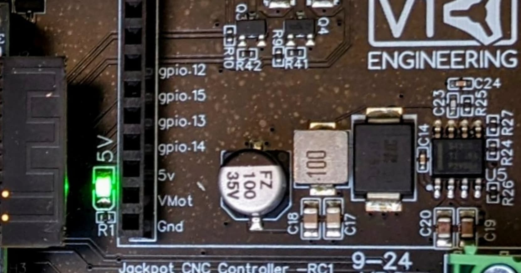
  • AMB 0–10 V (number 5 in pic) to GND: 7.5 V
  • gpio.14 (number 4 in pic) to GND: 3 V
  • Jackpot VMOT (number 2 in pic) to GND: 24 V
  • Jackpot 5V (number 3 in pic) to GND: 5V

The strange part: these voltages did not change at all when I sent G-code commands in FluidNC to vary the spindle speed (e.g., M3 S10000, M3 S25000, M3 S0). I also noticed that I cannot turn off the spindle using M5 or M3 S0, so it just keeps running at a constant speed.

Could this indicate that PWM isn’t being sent correctly from the FluidNC output pin? Or that the 0–10 V converter isn’t reacting to it?

I also updated the YAML configuration as suggested:


10V:
  output_pin: gpio.14
  forward_pin: gpio.13
  reverse_pin: gpio.15
  spinup_ms: 0
  spindown_ms: 0
  tool_num: 0
  speed_map: 0=0.000% 3500=10.000% 25000=90.000% 25000=100.000%

Thanks again for your help — really appreciate it!

That’s not the reference point we need for your measurments, it very specifically needs to be the AMB GND pin, the DMM (-) lead for this set of tests must physically be plugged into the AMB, not anywhere in the Jackpot.

The reason for this is to rule out various possible problems. Your AMB GND wire should be tied to the analog common of the 0-10V module, not VMOT (-).

That’s the pin below the “5” in your picture. Yes, in theory that pin should end up tied back to VMOT return through your module, but since your system isn’t working this is one of the data points we need. I’d move the return wire for the AMB to the module before repeating any tests.

We need to establish what your spindle “Sees” from the system, so the measurements need to be made with the DMM (-) connected to the spindle GND (At the AMB)

There’s a pot on the analog board which adjusts gain from U1, and this may need adjustment if we get your system to respond to commanding- but don’t touch the pot until we solve the voltage being fixed at 7.5V.

If you connect your DMM return to the AMB GND and still measure 7.5V at the 0-10V output terminal of the module, then we also want to check the GPIO 14 voltage on the jackpot. If GPIO 14 isn’t changing as you command different speeds in FluidNC, then the spindle board can’t work.

Your spindle won’t use the digital common, out1 or out2 (which you correctly did not wire to)

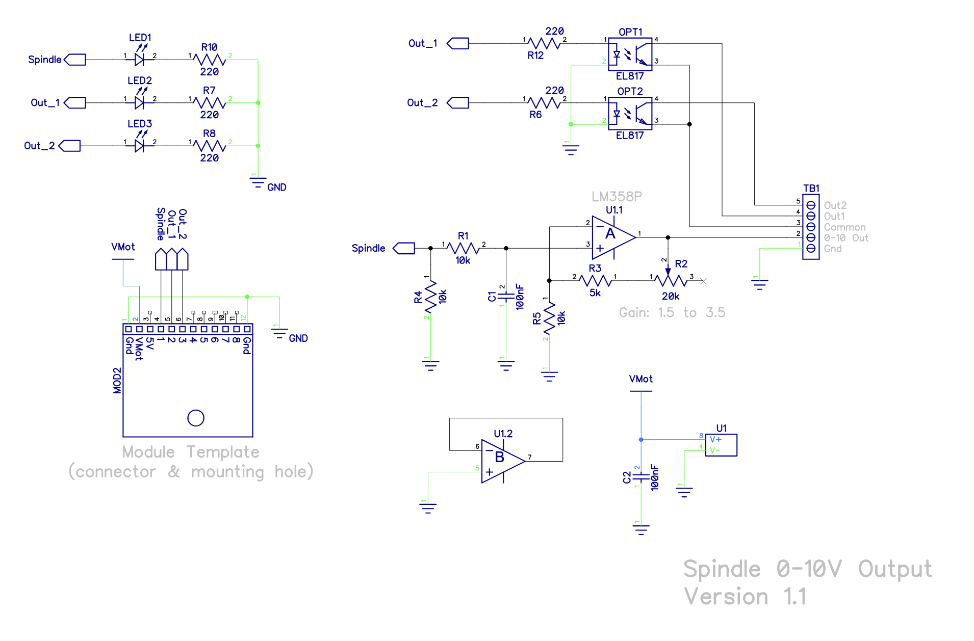
For reference, the schematic for the module and the pinout for the green connector is shown below:

CNC I/O Module VFD Description
Grn ACM Analog Common
0-10V VI signal voltage input
Com DCM Digital common
Out1 FOR Forward Direction Signal
Out2 REV Reverse Direction Signal (Optional)
1 Like

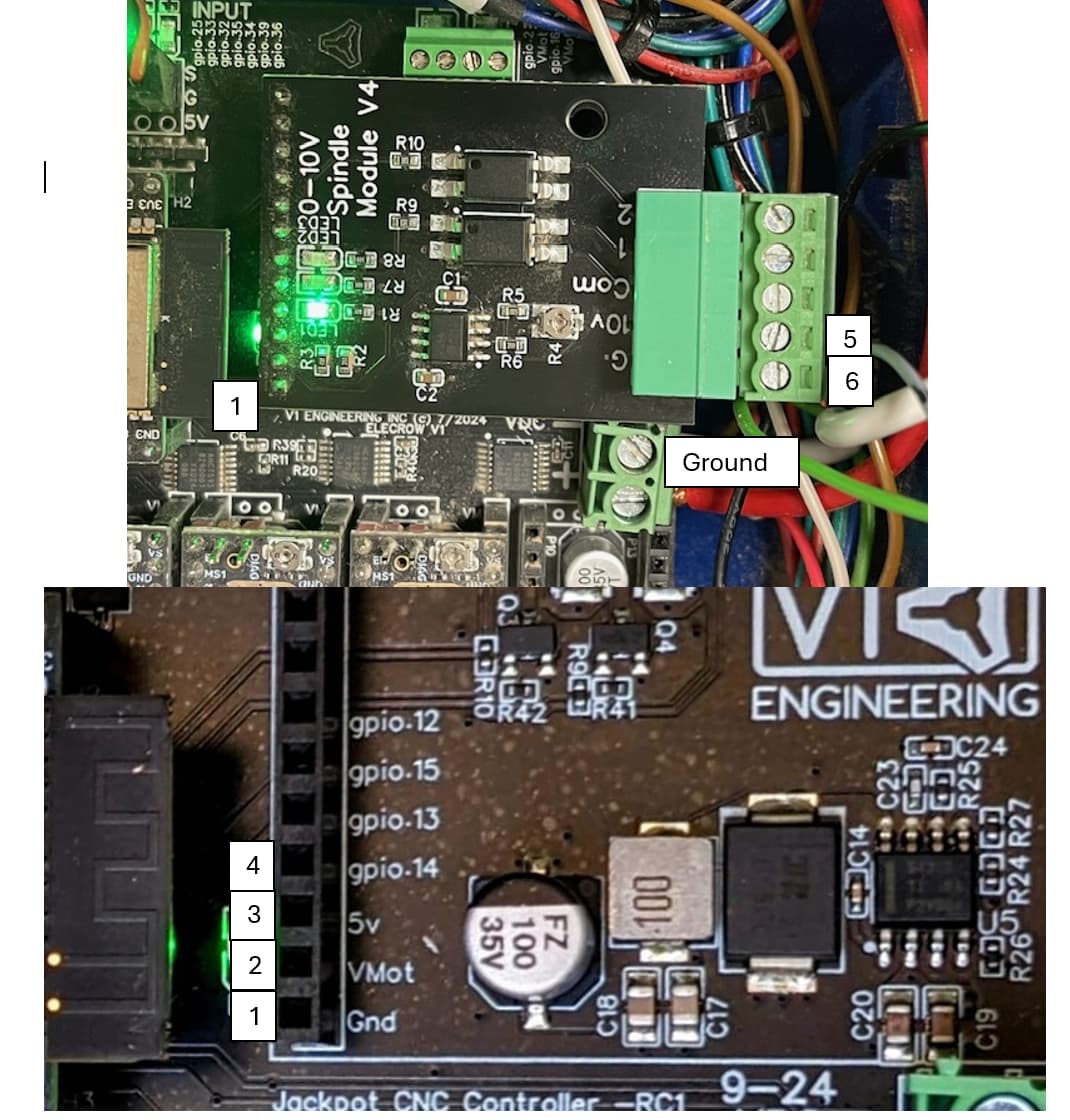
I re-ran the measurements today with the spindels GND conected to the 0-10V spindle modul (see image number 6), as you instructed. I also moved the AMB GND return wire to the analog common (ACM) terminal of the 0–10 V module.

Here are the new measurements (see img. number):

1: 0V
2: 24V
3: 5V
4: 3V
5: 7,5V

The big issue: None of the voltages change when I send different G-code commands like M3 S10000, M3 S25000, or M5. The analog output stays stuck at 7.5 V, and the GPIO input on the module (connected to gpio.14) doesn’t change either.

At this point, I’m starting to suspect that gpio.14 isn’t producing PWM correctly. Do you think it makes sense to test the GPIO pin directly with a scope or LED?

Thanks again for all the guidance — it’s a huge help!al common, out1 or out2 (which you correctly did not wire to)
[/quote]

Yes, if you have a scope then we want to see what pin 14 looks like as it is commanded to different speed settings

I don’t have a 0-10V module to test with, but I do have a couple of test Jackpots that I can try to recreate your configuration on, and similarly see what result I get.

Depending on what we see with the GPIO 14 levels, we may want to try a replacement ESP-32.

I believe GPIO 14 is PWM capable, and I believe other folks have been able to use Jackpot with Bart’s 0-10V. board.

So, let’s see what those scope shots look like.

1 Like

Thanks for the offer — I really appreciate you taking the time to test it on your side!

Unfortunately, I don’t have access to an oscilloscope right now. However, I’ll try to test GPIO 14 using an LED to at least get a rough idea of whether PWM is being output.

If I’m right, connecting a standard LED with a 220 Ω resistor between GPIO 14 (through the resistor) and GND should give a rough indication of PWM activity — the LED should glow dimmer at lower S-values and brighter at higher ones.
If it stays fully on, fully off, or doesn’t change at all, then GPIO 14 might not be generating any PWM.

It’s definitely not a precise test, but it should give us at least some idea of what’s going on.

What I also was thinking of: could the reason why GPIO 14 isn’t outputting any signal be because I didn’t include pwm_hz: 5000 in my 10V: block?

I’ve just added it now, but wanted to ask if that could be the root cause for the 0–10 V module not responding. I’ll definitely check this tomorrow first.

For reference, I’ve included the full YAML configuration below. The 10V: section that controls the spindle is at the bottom of the file.

Jackpot TMC2209
name: LowRider
meta: 19_12_2024PROJEKTARBEIT
stepping:
  engine: I2S_STATIC
  idle_ms: 255
  pulse_us: 2
  dir_delay_us: 1
  disable_delay_us: 0
  segments: 12
uart1:
  txd_pin: gpio.0
  rxd_pin: gpio.4
  rts_pin: NO_PIN
  cts_pin: NO_PIN
  baud: 115200
  mode: 8N1
i2so:
  bck_pin: gpio.22
  data_pin: gpio.21
  ws_pin: gpio.17
spi:
  miso_pin: gpio.19
  mosi_pin: gpio.23
  sck_pin: gpio.18
sdcard:
  cs_pin: gpio.5
  card_detect_pin: NO_PIN
  frequency_hz: 20000000
kinematics: {}
axes:
  shared_stepper_disable_pin: NO_PIN
  shared_stepper_reset_pin: NO_PIN
  homing_runs: 2
  x:
    steps_per_mm: 50
    max_rate_mm_per_min: 15000
    acceleration_mm_per_sec2: 200
    max_travel_mm: 800
    soft_limits: true
    homing:
      cycle: 2
      allow_single_axis: true
      positive_direction: false
      mpos_mm: 0
      feed_mm_per_min: 300
      seek_mm_per_min: 2000
      settle_ms: 500
      seek_scaler: 1.1
      feed_scaler: 1.1
    motor0:
      limit_neg_pin: gpio.25
      limit_pos_pin: NO_PIN
      limit_all_pin: NO_PIN
      hard_limits: true
      pulloff_mm: 3
      tmc_2209:
        addr: 0
        cs_pin: NO_PIN
        uart_num: 1
        step_pin: i2so.2
        direction_pin: i2so.1
        disable_pin: I2SO.0
        r_sense_ohms: 0.11
        run_amps: 0.8
        hold_amps: 0.5
        microsteps: 8
        toff_disable: 0
        toff_stealthchop: 5
        use_enable: false
        run_mode: StealthChop
        homing_mode: StealthChop
        homing_amps: 0.8
        stallguard: 0
        stallguard_debug: false
        toff_coolstep: 3
  y:
    steps_per_mm: 50
    max_rate_mm_per_min: 5000
    acceleration_mm_per_sec2: 200
    max_travel_mm: 1600
    soft_limits: true
    homing:
      cycle: 2
      allow_single_axis: true
      positive_direction: false
      mpos_mm: 0
      feed_mm_per_min: 300
      seek_mm_per_min: 1500
      settle_ms: 500
      seek_scaler: 1.1
      feed_scaler: 1.1
    motor0:
      limit_neg_pin: gpio.33
      limit_pos_pin: NO_PIN
      limit_all_pin: NO_PIN
      hard_limits: true
      pulloff_mm: 3
      tmc_2209:
        addr: 1
        cs_pin: NO_PIN
        uart_num: 1
        step_pin: i2so.5
        direction_pin: i2so.4
        disable_pin: I2SO.7
        r_sense_ohms: 0.11
        run_amps: 0.8
        hold_amps: 0.5
        microsteps: 8
        toff_disable: 0
        toff_stealthchop: 5
        use_enable: false
        run_mode: StealthChop
        homing_mode: StealthChop
        homing_amps: 0.8
        stallguard: 0
        stallguard_debug: false
        toff_coolstep: 3
    motor1:
      limit_neg_pin: gpio.35
      limit_pos_pin: NO_PIN
      limit_all_pin: NO_PIN
      hard_limits: true
      pulloff_mm: 3
      tmc_2209:
        addr: 3
        cs_pin: I2SO.14
        uart_num: 1
        step_pin: i2so.13
        direction_pin: i2so.12
        disable_pin: I2SO.15
        r_sense_ohms: 0.11
        run_amps: 0.8
        hold_amps: 0.5
        microsteps: 8
        toff_disable: 0
        toff_stealthchop: 5
        use_enable: false
        run_mode: StealthChop
        homing_mode: StealthChop
        homing_amps: 0.8
        stallguard: 0
        stallguard_debug: false
        toff_coolstep: 3
  z:
    steps_per_mm: 200
    max_rate_mm_per_min: 300
    acceleration_mm_per_sec2: 50
    max_travel_mm: 100
    soft_limits: true
    homing:
      cycle: 1
      allow_single_axis: true
      positive_direction: true
      mpos_mm: 100
      feed_mm_per_min: 300
      seek_mm_per_min: 800
      settle_ms: 500
      seek_scaler: 1.1
      feed_scaler: 1.1
    motor0:
      limit_neg_pin: NO_PIN
      limit_pos_pin: gpio.32
      limit_all_pin: NO_PIN
      hard_limits: true
      pulloff_mm: 3
      tmc_2209:
        addr: 2
        cs_pin: NO_PIN
        uart_num: 1
        step_pin: i2so.10
        direction_pin: i2so.9
        disable_pin: I2SO.8
        r_sense_ohms: 0.11
        run_amps: 0.8
        hold_amps: 0.5
        microsteps: 8
        toff_disable: 0
        toff_stealthchop: 5
        use_enable: false
        run_mode: StealthChop
        homing_mode: StealthChop
        homing_amps: 0.8
        stallguard: 0
        stallguard_debug: false
        toff_coolstep: 3
    motor1:
      limit_neg_pin: NO_PIN
      limit_pos_pin: gpio.34
      limit_all_pin: NO_PIN
      hard_limits: true
      pulloff_mm: 3
      tmc_2209:
        addr: 3
        cs_pin: I2SO.19
        uart_num: 1
        step_pin: i2so.18
        direction_pin: i2so.17
        disable_pin: I2SO.16
        r_sense_ohms: 0.11
        run_amps: 0.8
        hold_amps: 0.5
        microsteps: 8
        toff_disable: 0
        toff_stealthchop: 5
        use_enable: false
        run_mode: StealthChop
        homing_mode: StealthChop
        homing_amps: 0.8
        stallguard: 0
        stallguard_debug: false
        toff_coolstep: 3
control:
  safety_door_pin: NO_PIN
  reset_pin: NO_PIN
  feed_hold_pin: NO_PIN
  cycle_start_pin: NO_PIN
  macro0_pin: NO_PIN
  macro1_pin: NO_PIN
  macro2_pin: NO_PIN
  macro3_pin: NO_PIN
  fault_pin: NO_PIN
  estop_pin: NO_PIN
coolant:
  flood_pin: gpio.2
  mist_pin: gpio.16
  delay_ms: 0
probe:
  pin: gpio.36:low
  toolsetter_pin: NO_PIN
  check_mode_start: false
  hard_stop: false
macros: {}
start:
  must_home: false
  deactivate_parking: false
  check_limits: true
parking:
  enable: false
  axis: Z
  target_mpos_mm: -5
  rate_mm_per_min: 800
  pullout_distance_mm: 5
  pullout_rate_mm_per_min: 250
user_outputs:
  analog0_pin: NO_PIN
  analog1_pin: NO_PIN
  analog2_pin: NO_PIN
  analog3_pin: NO_PIN
  analog0_hz: 5000
  analog1_hz: 5000
  analog2_hz: 5000
  analog3_hz: 5000
  digital0_pin: gpio.26
  digital1_pin: gpio.27
  digital2_pin: NO_PIN
  digital3_pin: NO_PIN
  digital4_pin: NO_PIN
  digital5_pin: NO_PIN
  digital6_pin: NO_PIN
  digital7_pin: NO_PIN
user_inputs:
  analog0_pin: NO_PIN
  analog1_pin: NO_PIN
  analog2_pin: NO_PIN
  analog3_pin: NO_PIN
  digital0_pin: NO_PIN
  digital1_pin: NO_PIN
  digital2_pin: NO_PIN
  digital3_pin: NO_PIN
  digital4_pin: NO_PIN
  digital5_pin: NO_PIN
  digital6_pin: NO_PIN
  digital7_pin: NO_PIN
arc_tolerance_mm: 0.002
junction_deviation_mm: 0.01
verbose_errors: true
report_inches: false
enable_parking_override_control: false
use_line_numbers: false
planner_blocks: 32
10V:
  output_pin: gpio.14
  forward_pin: gpio.13
  reverse_pin: gpio.15
  pwm_hz: 5000
  spinup_ms: 0
  spindown_ms: 0
  tool_num: 0
  disable_with_s0: true
  s0_with_disable: true
  speed_map: 0=0.000% 3500=10.000% 25000=90.000% 25000=100.000%

Thanks again for all the help!

I don’t think so. 5000 is the default value so that is what it should be using if not specified.