Hey, @Florian- I have been able to get some test results finally.
Thank you @Jonathjon for helping me out with a 0-10V spindle expansion module.
Short answer: This module, on my test Jackpot V1, works as expected doing 0-10V.
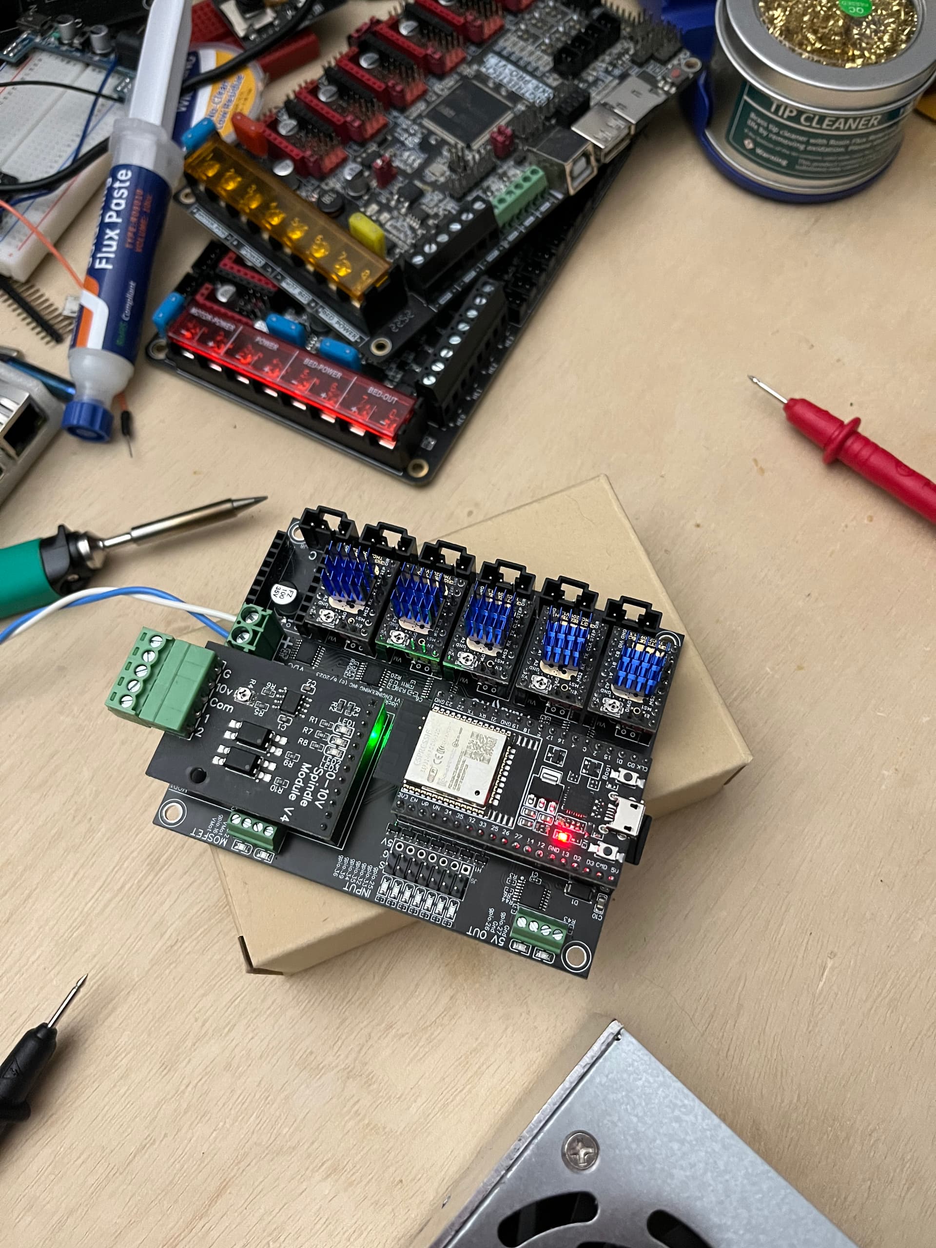
Here’s the board, set up on my overflow test bench:
I added this to my test LR4 Jackpot config.yaml
10V:
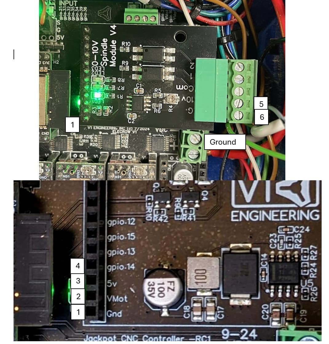
output_pin: gpio.14
forward_pin: gpio.13
reverse_pin: gpio.15
spinup_ms: 0
spindown_ms: 0
tool_num: 0
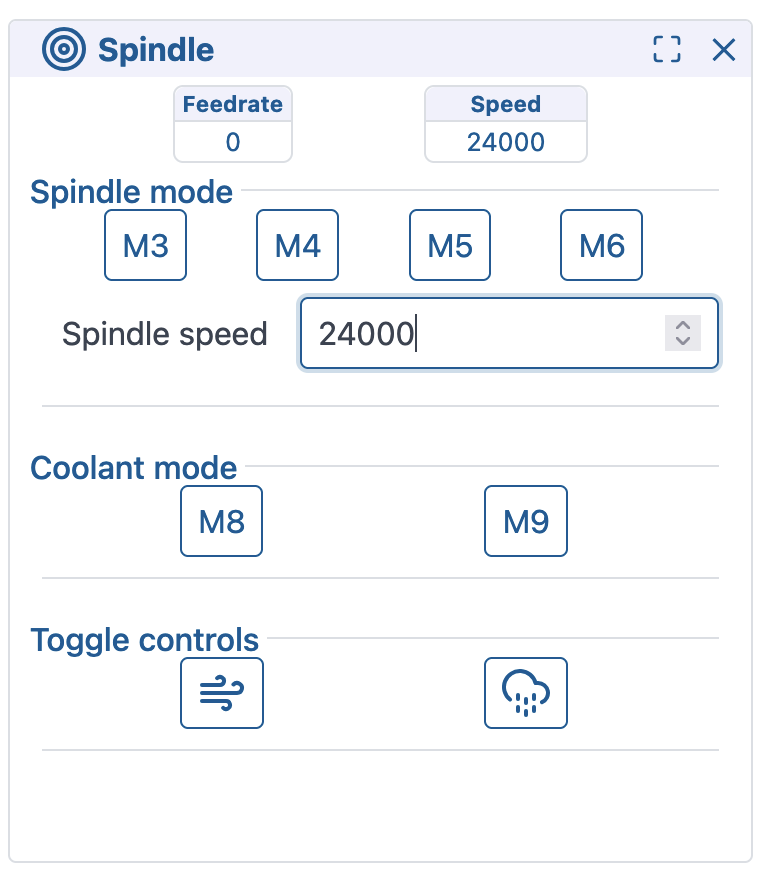
speed_map: 0=0% 6000=0% 24000=100%
When I start up my Jackpot with this config block in there, I get this line in $SS output:
[MSG:INFO: 10V Spindle Ena:NO_PIN Out:gpio.14 Dir:NO_PIN Fwd:gpio.13 Rev:gpio.15 Freq:5000Hz Period:8191]
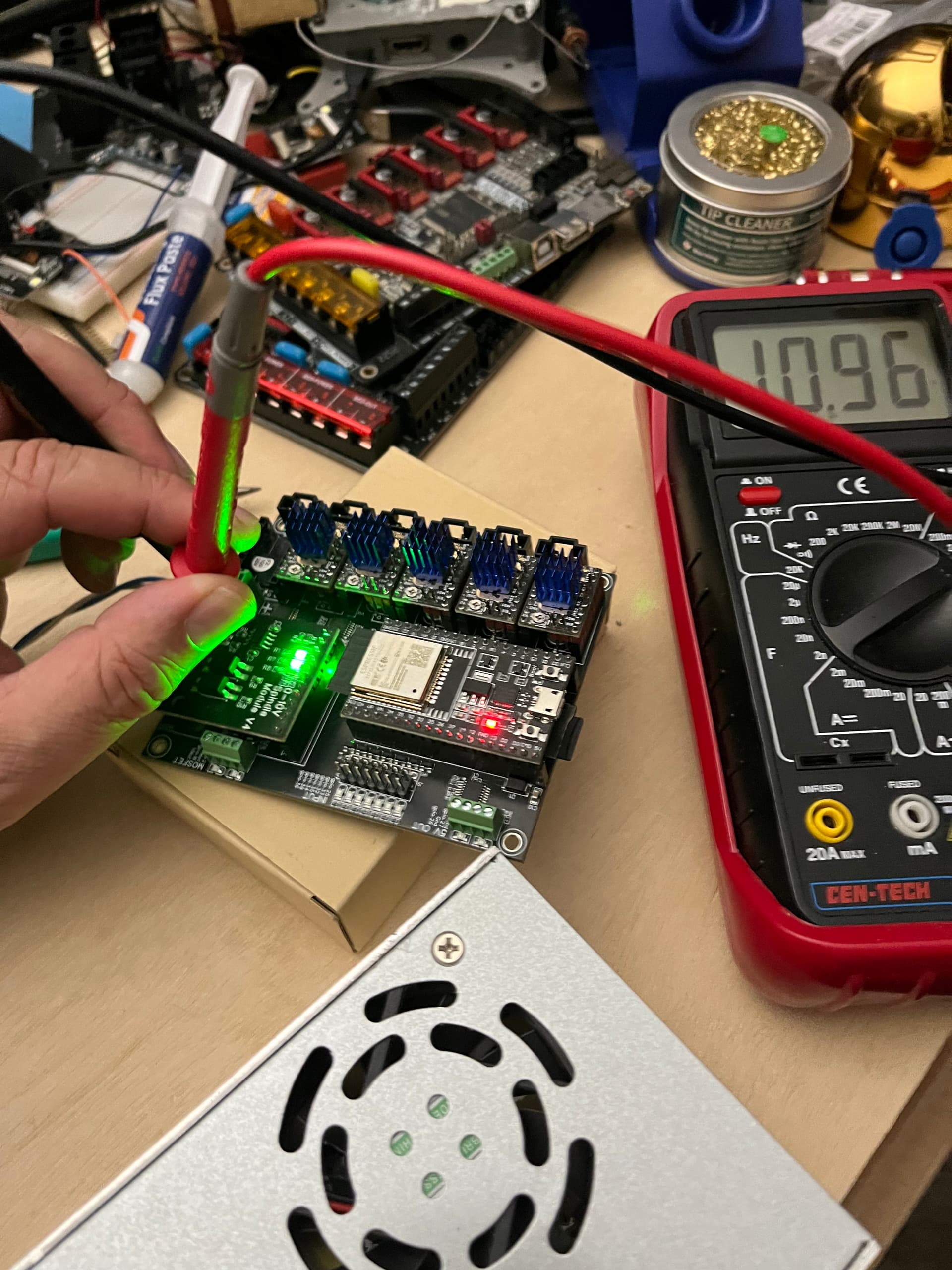
When I command the spindle clockwise and to 24000 RPM, I see the voltage on the board. In this case, without adjusting anything, I’m getting 11V when commanding 24000 RPM.
(I would need to adjust the trim pot on the expansion module to get this to exactly 10.0V if I were actually hooking up a spindle)
When I’ve done this commanding, I see 3.25V with the DMM on the Jackpot gpio.14 over at the expansion header. If I command off the spindle, we go back to 0V on the output.
So, my assessment is that your board has a blown ESP-32 GPIO 14, or your config file is wrong somehow. I’ll re-study this thread to see if anything catches my eye.
I’d love if the rest of the forum participants take a 2nd look as well to see if anything jumps out.