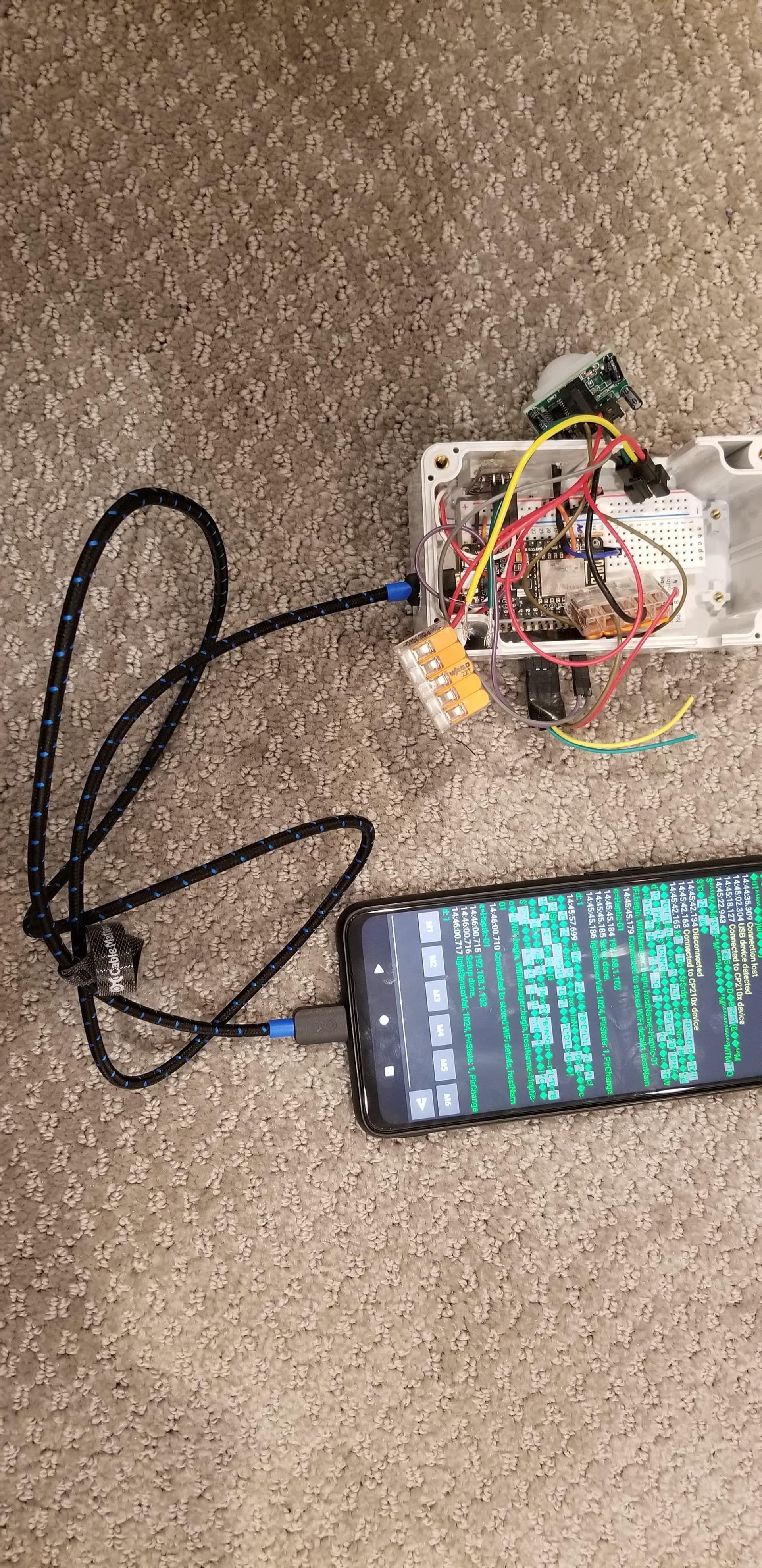
Bought USB C to micro USB cable, able to connect and power ESP8266 and comm from Android phone (an old backup phone) via some rando Serial Com Monitor app. Chrome 120 on my android doesn’t seem to have Web Serial enabled/supported, maybe there’s a dev switch, am searching for pure/partial browser based options. But worse case a basic android app on phone could be USB connected directly to an ESP…
1 Like
Ok, i am in.
Ordered one from m5 and theyvare in sinapour, so i might get it in a week. Lol.
Would be great as wifi or BT but that ups the complexity by heaps.
From your videos, and thanks for those!, just that functionality will be very useful
1 Like
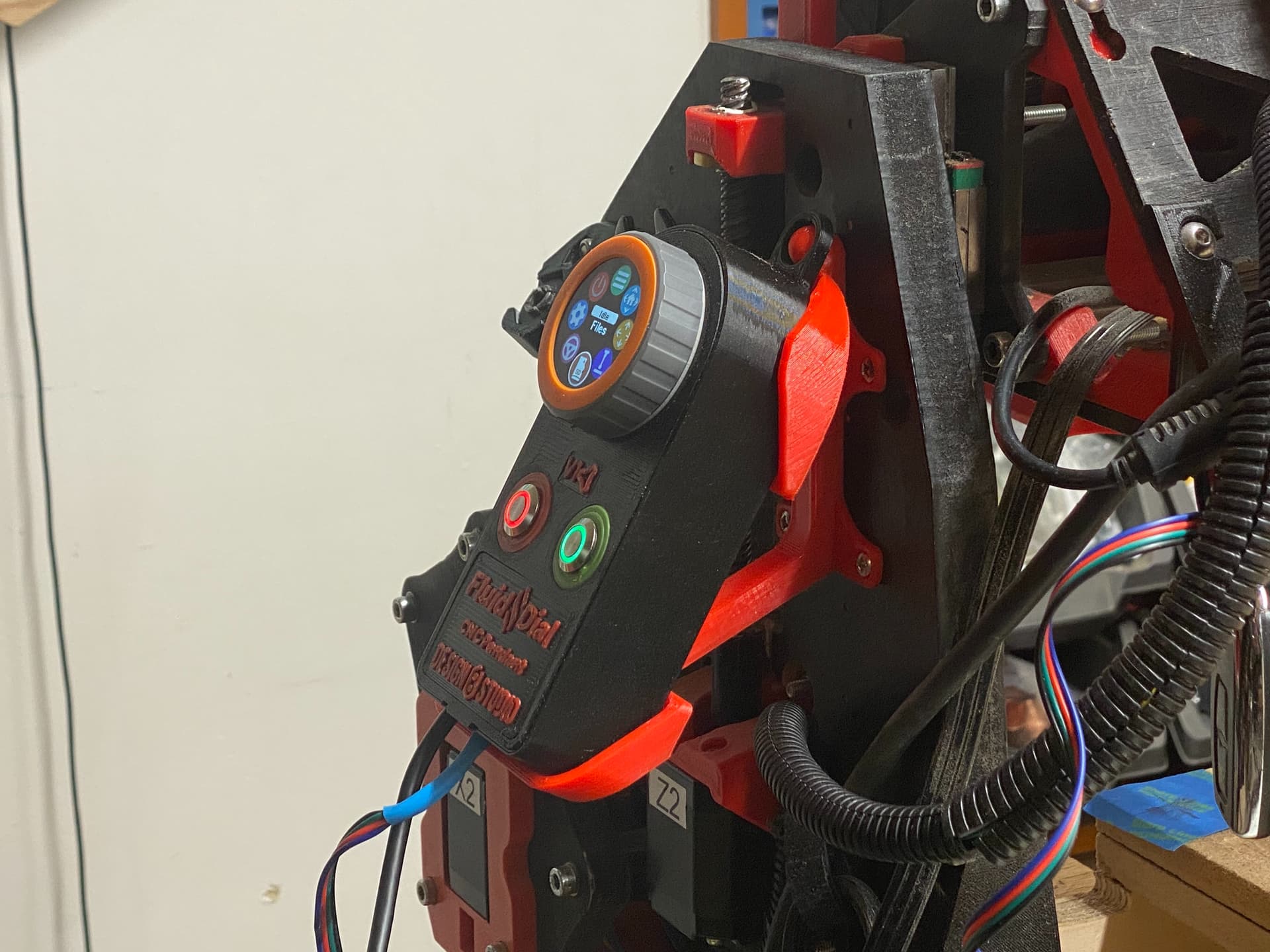
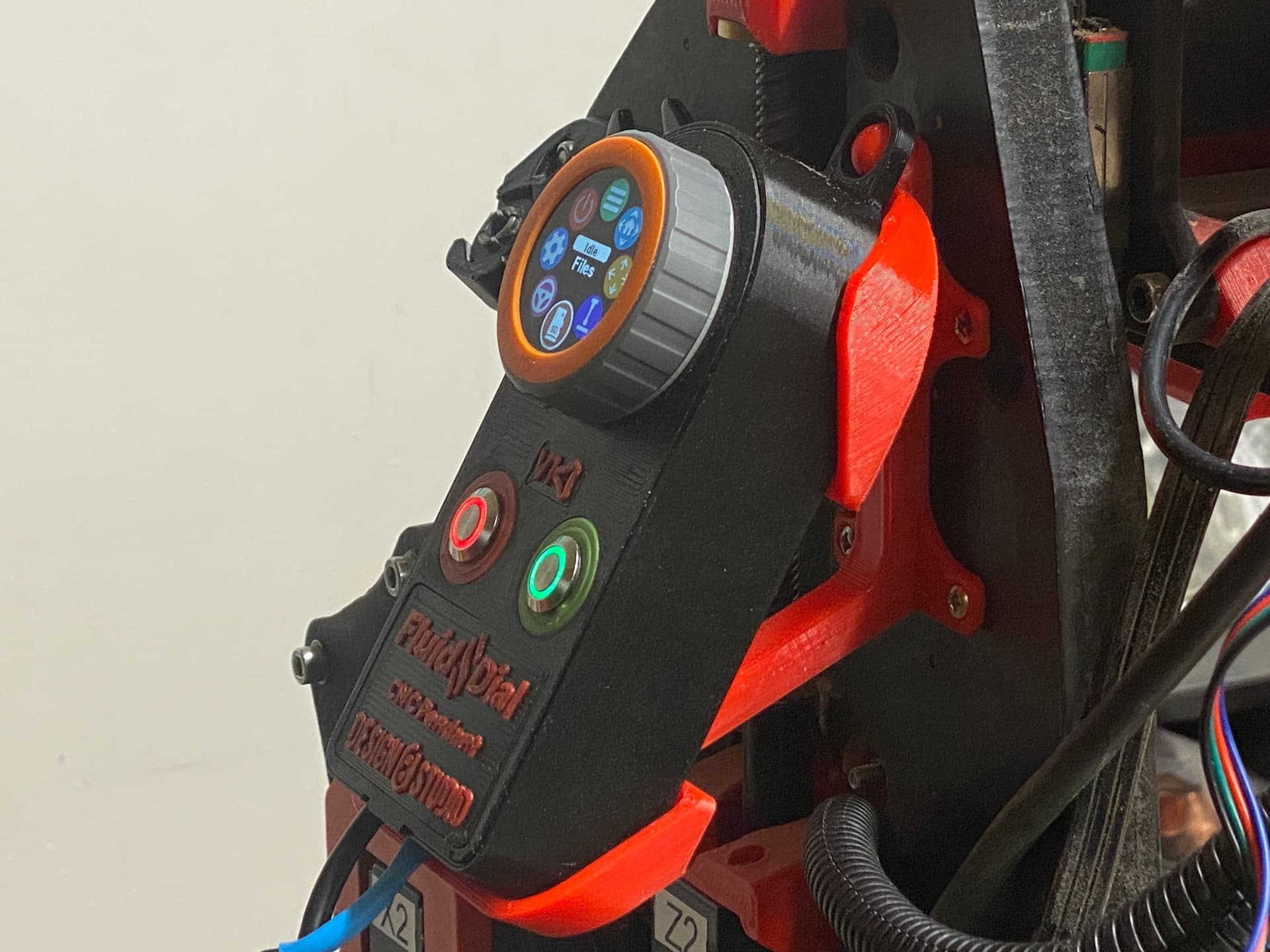
Update: The Fluid Dial pendant dev team has a beta version of the firmware that can now access SD card files and launch (run) gcode files… It’s not quite ready for prime time, but ready enough that Bart said for it to be moved into the “Main” branch. It still needs some work, but… earlier tonight I built and loaded a “behind the scenes” predecessor version of that firmware build, and I actually used it to browse several subfolder layers deep and launch and run a gcode cut file!
3 Likes
Thanks for posting all of this Doug. I have my dial sitting here on the desk with the interface after a successful build. But I cannot for the life of me locate the encoder.h file that requires modification. Any specifics on how you got it to show up?? I don’t have the specific folder listed on the wiki. Any tips?
Have you downloaded any of the ongoing build branches from the Github repo? These would be for “PendantsForFluidNC” — and folder structure to the encoder.h file is: M5Dial_Scenes > src
However, I have never had to edit any encoder.h file to get a working unit. What editing are you looking to do?
I’m trying to do this step:
I did download the entire Scenes repo. I also found the necessary GrblParser.h and I get a successful build. But then I ran into this paragraph, and the only encoder.h file I see doesn’t have the define statements in it. Also, the folder structure given on the wiki for this step doesn’t reflect the structure in VSCode, platformIO or on my drive.
The screen on the dial looks like the one above without the Red and Green button functions. Just jog shows. It beeps when I press the screen, but nothing changes when I turn the encoder.
Do you happen to have a link to the latest repo? Maybe I should start there. (Is the change still needed for this repo?) One of the gripes I have with so many places on the internet is the lack of dates. It would be great to know the last update on stuff that is still changing rapidly. At least on a forum like this the posts are dated.
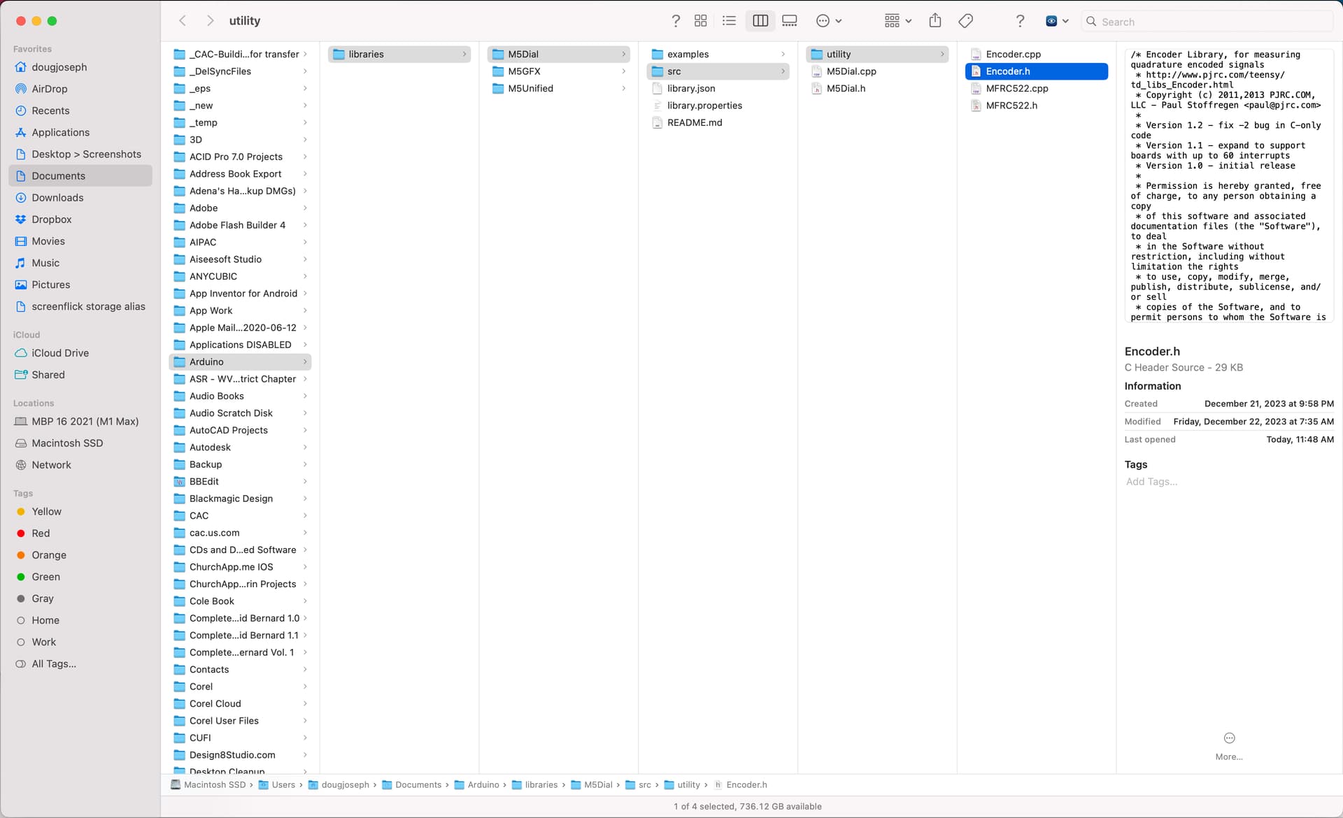
Ah, I had forgotten about that fix. The screen shot below reveals the location of where I found one that met the description and could be edited. Although, the encoder.h I had found and edited for that fix, was not located in a .pio of the current build, and I had located it by manually searching my hard drive, and I honestly don’t know if it was the right one, and don’t know if it had any effect. Notice at the bottom of the screen shot, the path to the folder is shown, as well as the GUI interface revealing it.
They’ve been developing quickly, with quite a few branches, and sometimes the branch names seem cryptic to someone not involved with the dev work, so I’ve been keeping up by reading over their dev team dialog on Discord, and trying out branches that seem like the most recent. They seem to be getting close to pulling it together in a release build.
We’ll have to see if that fix is still a thing (still needed or called for) after the release, and hopefully get more refinement on the doc for it.
Thanks Doug. This helped immensely. I’ve been able to make the change. Like you, I’m not completely sure this will be reflected when I build the PlatformIO project, but at least I’ve made the bug fix.
Sincerely appreciated.
1 Like
I must have angered the parcel delivery gods, as now my M5 Dial is shipping from china.
So probably not going to get it in a week. Sigh.
1 Like

NOTE: As of today, Jan 27, 2024, there are now 3 editions of this (two with magnets, and a third without magnets):**
- v1.4 - 1st edition - GET IT HERE - magnets on outsides, opposing magnets touching
- v1.5 - 2nd edition - GET IT HERE - magnets on insides, opposing magnets not touching
- v1.6 - 3rd edition - GET IT HERE - no magnets at all, just a press fit insertion & removal
The two prior versions were revised to have less overhang for better print results, and were accordingly renumbered in their version number designations. Below are prior announcements, left unchanged.
NOTE: As of today, Jan 22, 2024, new versions (v1.2) of both the cradle and case bottom, have been published on the Printables listings, which were modified to have the magnets glued in from the reverse sides, so a magnet’s grip from one side can’t pull out the corresponding magnet from the other side. Both magnets will pull each other “into” their sockets instead of “out of” their sockets. (They pull through thin layers of printed plastic.) Below is a link to the new version:
https://www.printables.com/model/733285-cradle-for-fluidnc-dial-pendant-on-yz-plate-of-low
Previous update: As of today, Jan 14, 2024, new versions (v1.1) of both the cradle and case bottom, have been published on the Printables listings, which were modified to ensure that the cradle can be installed without any interference with the two large tool access holes on the YZ plate. If you already downloaded the cradle and corresponding case bottom, please re-download before printing!
So, the FluidNC dev team is continuing their work apace, and meanwhile I have designed a cradle for holding the FluidNC Dial pendant on the YZ plate of a LowRider v3. It’s made to not just cradle it but to also hold onto it by use of 8 sets of tiny round magnets (2mm thick x 5 mm diameter). This means I also needed to remix the case bottom again, to add space for 8 magnets to be glued onto the lower face of it. I’ve printed the new case bottom and the new cradle. This is about the 3rd iteration of the design. Stay tuned for either pics or video!
Here’s the download link: Cradle for FluidNC Dial Pendant on YZ plate of LowRider v3 CNC (v1.4) by Doug Joseph (design8studio) | Download free STL model | Printables.com

2 Likes
That turned out really nice.
2 Likes
High Doug,
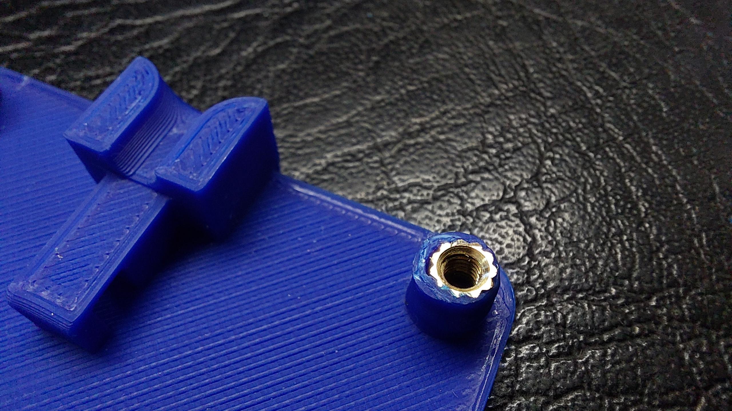
thanx for the new pendant STL files. I would suggest to increase the diamter of the front plate stand-offs when using threaded inserts. Otherwise its a little flimpsy.
Also i would prefer a standard m3 screw lenght of 20mm.
1 Like
I’m a little confused. I am not using threaded inserts, and I don’t remember suggesting them. Did something that I said the above imply that I was using them? Certainly, it would be doable to remix to try to accommodate them, but as it is, I’m just using screws biting into the PLA plastic … with the screws just creating their own threads.
It’s also possible to use inserts in a design not originally indending them, but you have to use enough parameters when slicing to leave plastic, and then drill out the hole to a size appropriate for the insert being used. There are a huge number of different ODs for the brass thermal inserts, so it takes understanding what size opening must be present.
1 Like
@MakerJim Certainly in many cases that can work. In this case, I noticed that the original design (from which I remixed) has the screws located quite close to the edge of the body, and not a lot of spare thickness around the screw holes. The tight placement means that unless a remix has moved the screw holes to allow room for more plastic, the standoffs just don’t have the bandwidth to avoid a collision when trying thicken them, and are barely thick enough as is, or even not thick enough.
1 Like
NOTE: As of today, Jan 22, 2024, new versions (v1.2) of both the cradle and case bottom, have been published on the Printables listings, which were modified to have the magnets glued in from the reverse sides, so a magnet’s grip from one side can’t pull out the corresponding magnet from the other side. Both magnets will pull each other “into” their sockets instead of “out of” their sockets. (They pull through thin layers of printed plastic.) Below is a link to the new version:
https://www.printables.com/model/733285-cradle-for-fluidnc-dial-pendant-on-yz-plate-of-low
Previous update: As of today, Jan 14, 2024, new versions (v1.1) of both the cradle and case bottom, have been published on the Printables listings, which were modified to ensure that the cradle can be installed without any interference with the two large tool access holes on the YZ plate. If you already downloaded the cradle and corresponding case bottom, please re-download before printing!
Regarding the placement for installing the cradle, see the following notes that were added to the Printables listings:
Placement on YZ plate:
There are two keys to good placement.
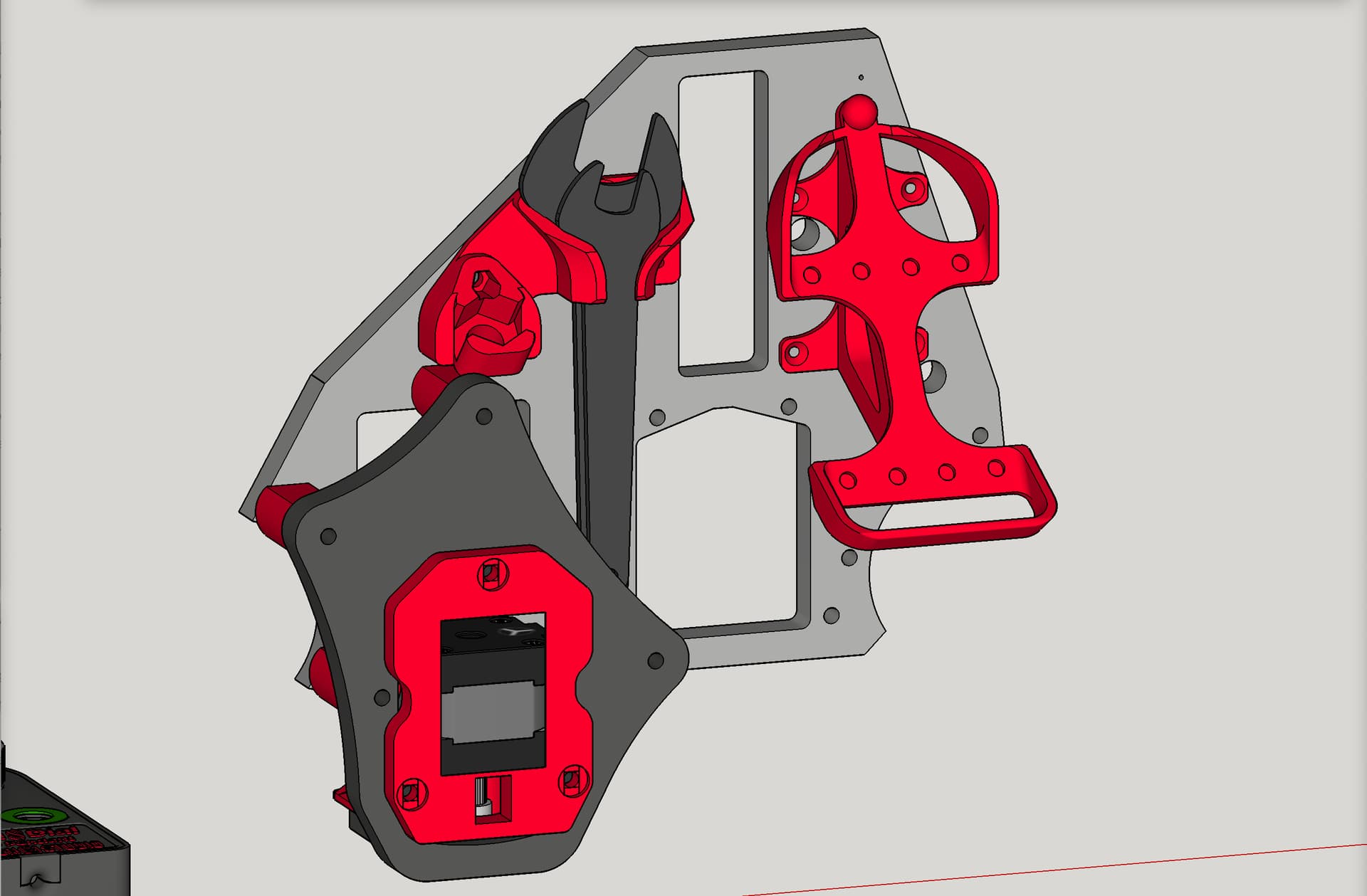
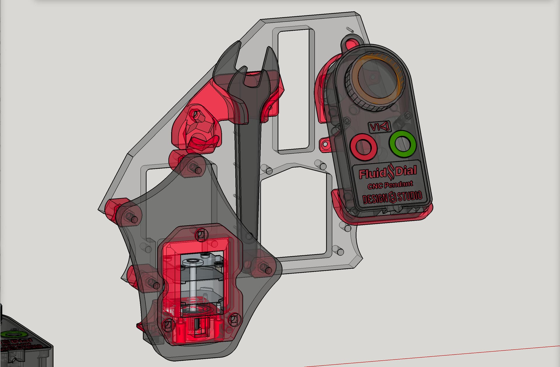
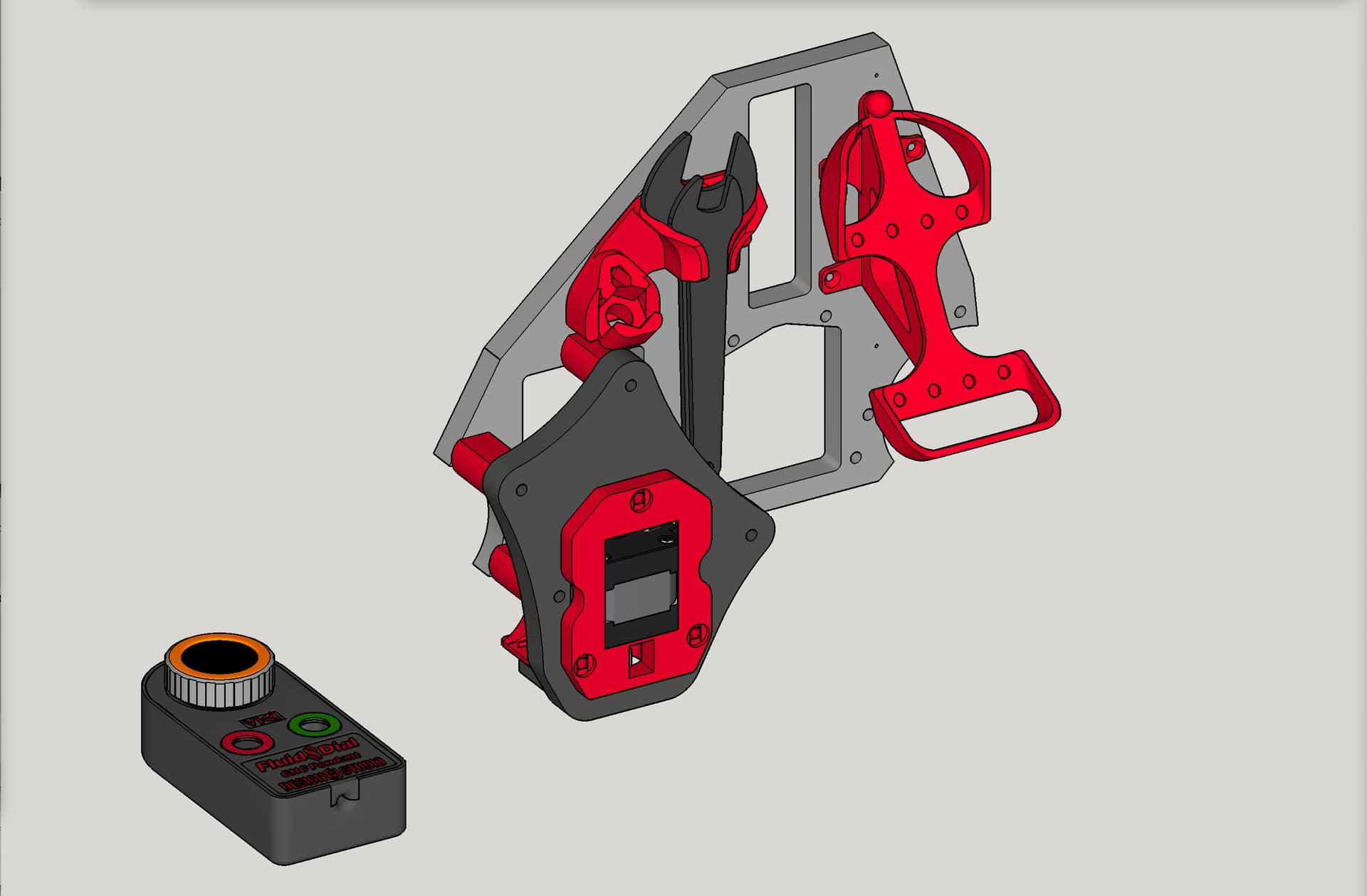
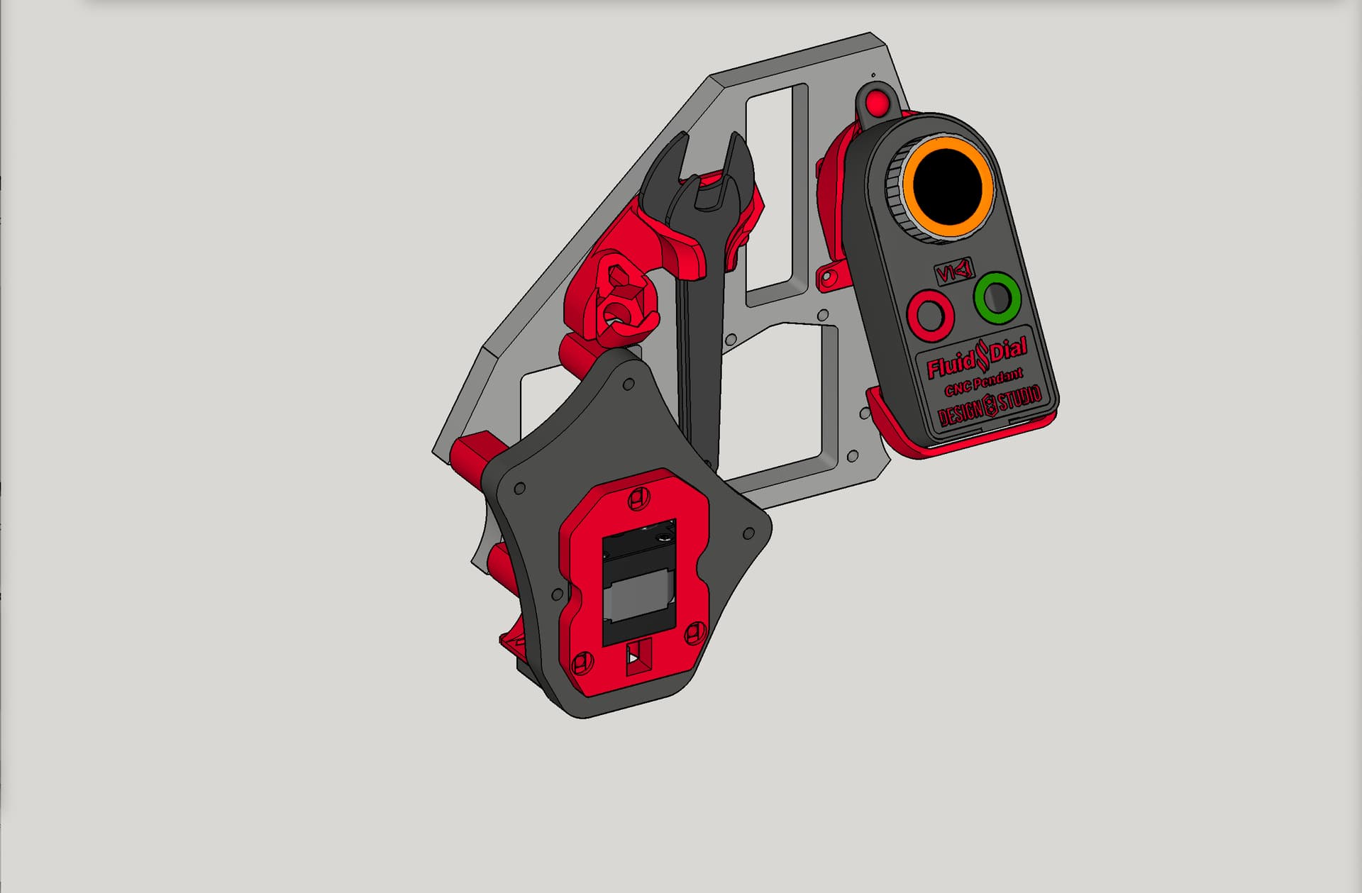
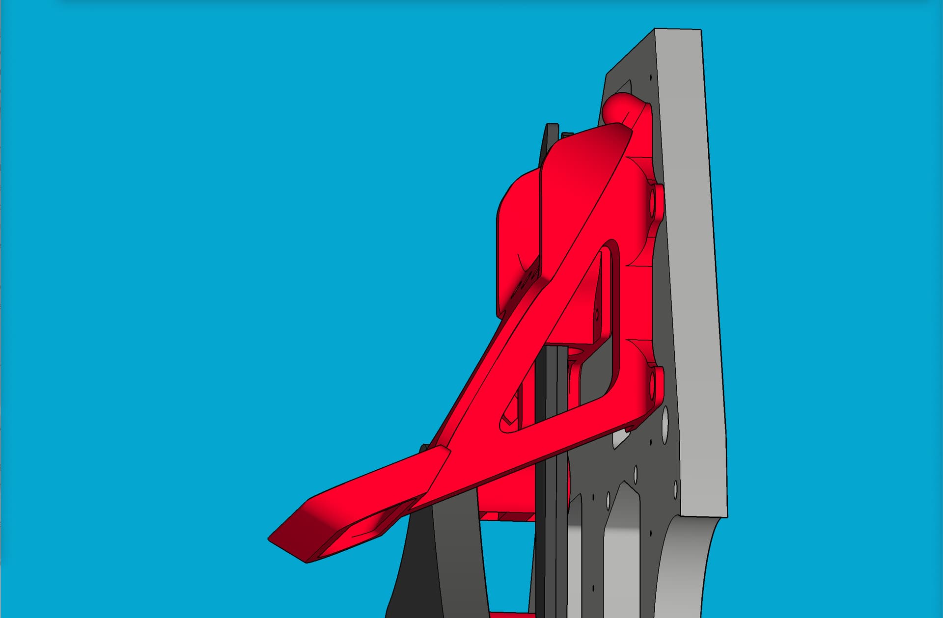
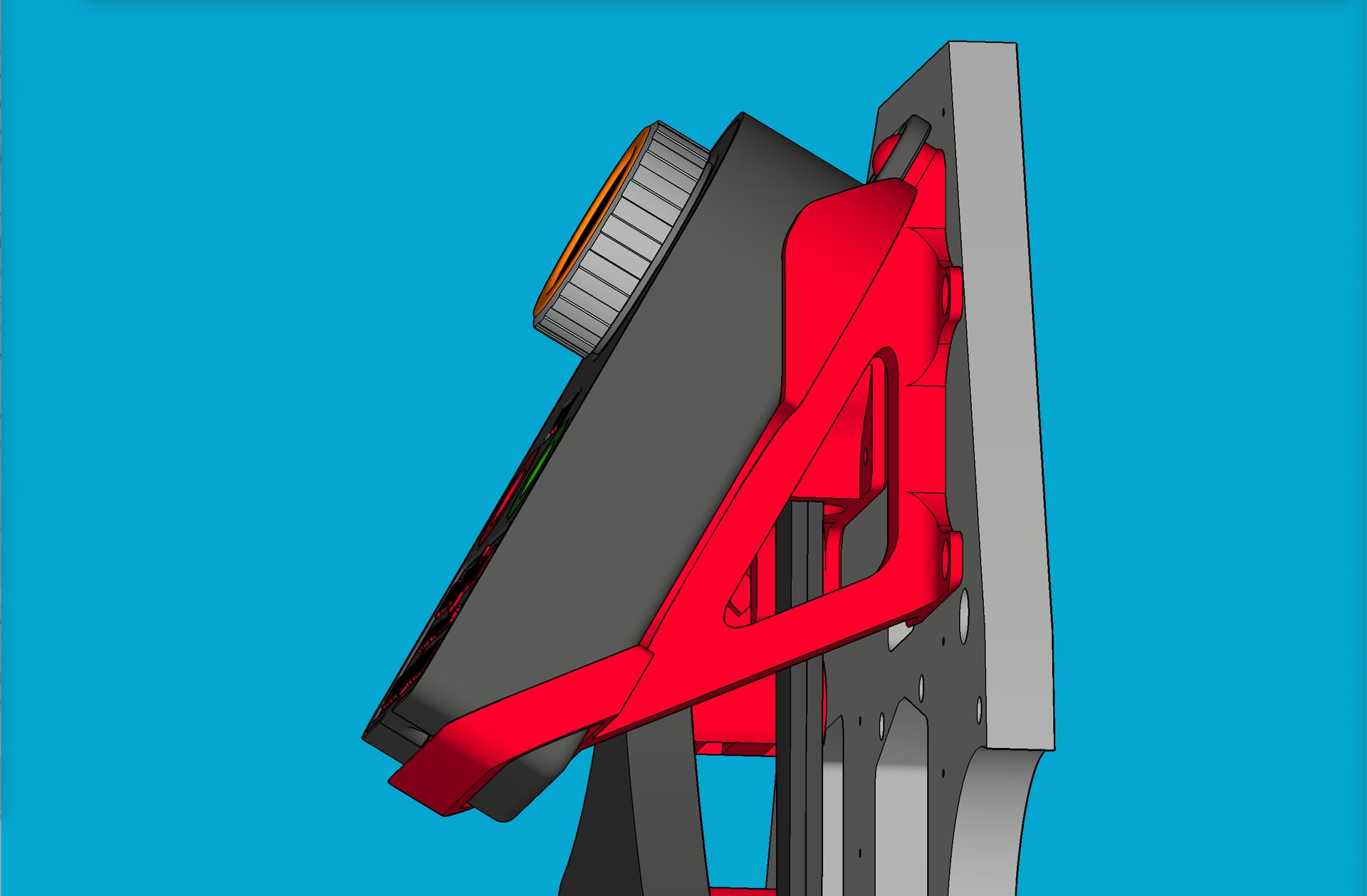
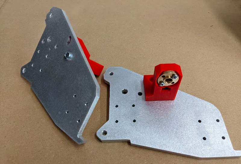
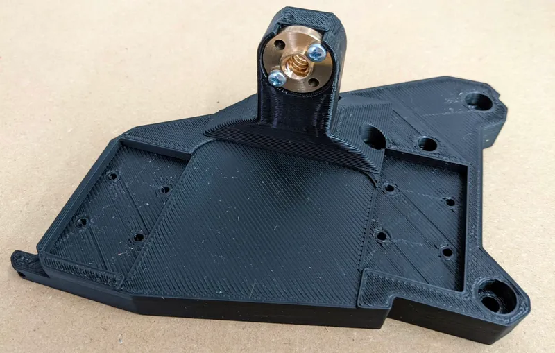
The first key is to avoid any chance of collision between the new cradle and your existing XZ lead screw stub. The two versions of the stub can be seen in the images below:
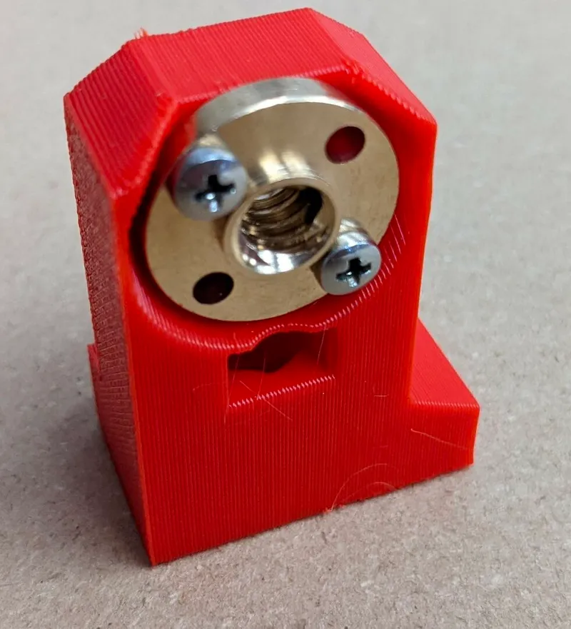
Assuming your LowRider is already assembled and functional, it’s advisable to raise your gantry’s Z height so that the stub is positioned so that you can see exactly how to place your new cradle to be far enough away from it.
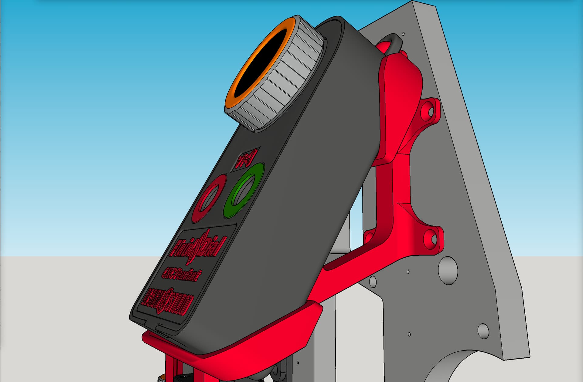
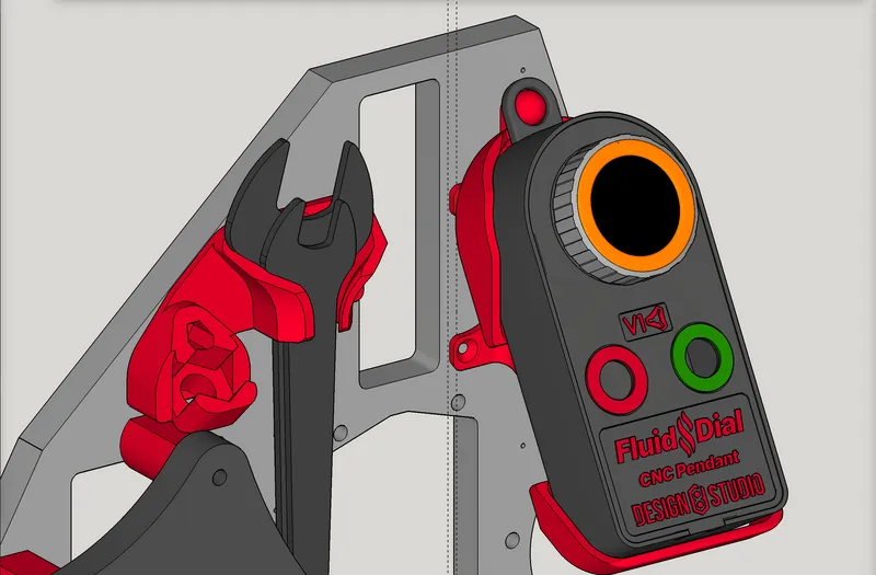
Because I pre-drilled for, and installed, the first-generation prototype of the cradle, which had no side walls like the current generation, that older version could be positioned very close to the stub. When I later installed the current design with side walls, using the same pre-drilled holes, I had a collision issue, and had to carve out a small portion of my cradle. Because of that, I can only guess at exactly how far away (from the opening for the stub in the YZ plate) you need to install the cradle. My guess is between 1/8" and ¼" away should be enough. In the illustration below (from my 3D modeling in SketchUp), there are two vertical guidelines. One guideline is 1/8" from the opening, and the other guideline is ¼" from the opening. The cradle is installed with its edge somewhere between the two guidelines.
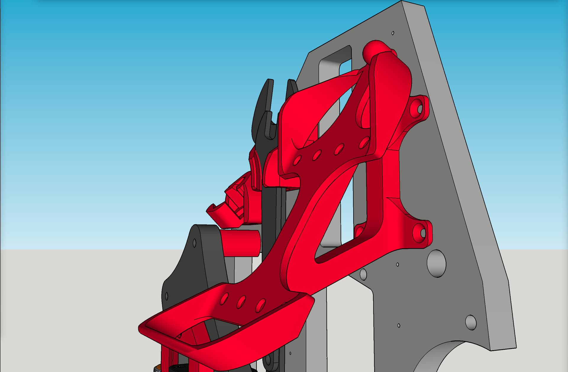
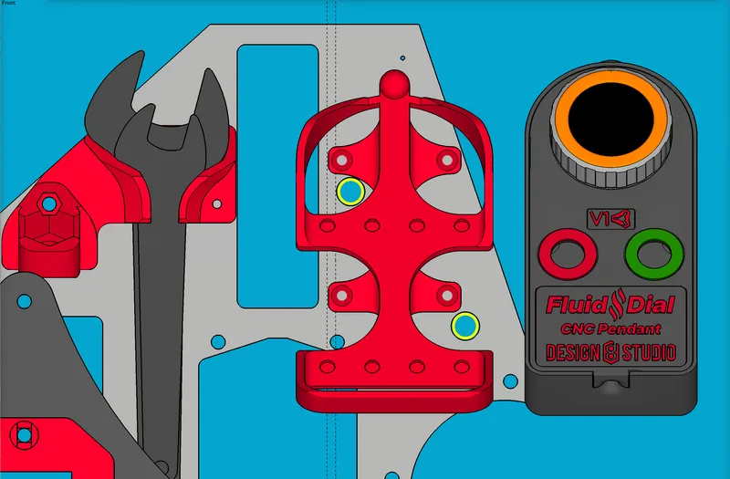
The second key to good placement is to make sure that you still have access to the two large holes in the YZ plate that allow access to the screws holding the gantry beam to the XZ plates.
In the illustration below (from my 3D modeling in SketchUp), you can see the two large holes highlighted in yellow. Notice that the cradle can be installed so that tool access to those holes is still allowable. Also, here again is another view of those two vertical guidelines. One guideline is 1/8" from the opening, and the other guideline is ¼" from the opening. The cradle is installed with its edge somewhere between the two guidelines.
Just leaving this note here in case it helps anyone with graphics work. The font family used for the FluidNC logo and for the Fluid Dial logo is named “Inter” and also referred to as “Inter UI” — and specifically, the font face (within that family) that’s used is “Inter Black Italic” aka “InterUI BlackItalic.”
You can get this font for free on Google’s font library here:
The latter is not too hard to implement. The former would take a little more doing.
Usually the longer the screw, the more valuable it is, so M3x16 should be easier to come up with than M3x20. Did I understand you want it to require longer screws than the 16mm?
Here’s where I had mentioned the length of screw called for was 16mm: Fluid Dial (Fluid NC dial pendant by Bart Dring, using M5 Stack's M5 Dial) - #6 by DougJoseph
Note: As of the latest remix, it can also accommodate either M3 x 16mm or M3 x 18mm, because the depth of the well is at 19mm, if I am measuring correctly. At 16mm, the tip of the screw is only biting into about half of the screw hole in the lid. At 18mm it’s biting into almost all of the screw hole in the lid.
If it was remixed to add 2 more millimeters to the screw hole total depth, it would shift from allowing either 16 or 18, to requiring between 18 to 20.
Update on firmware development:
I inquired on the developer Discord thread about what is called for in order to build and test the latest — what hardware wiring changes are needed, which branch to use, etc. Here are the details of the answer:
- Update FluidNC firmware using the branch labelled “MSG_JSON” — GitHub - bdring/FluidNC at MSG_JSON
- Update Fluid Dial firmware using the branch labelled “reactiveJSON” — GitHub - bdring/PendantsForFluidNC: Pendants for controlling FluidNC CNC firmware
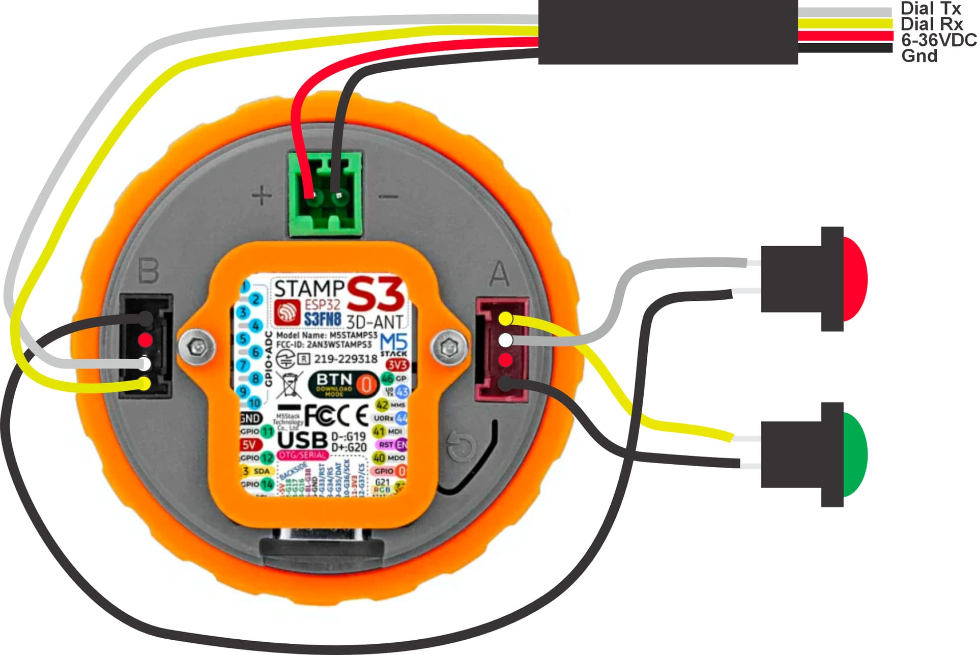
- Change hardware wiring as follows: “flip A/B and swap Green/Red button wires.” (I’m still checking to see what that means.)
Regarding the “flip A/B” part, it’s referring to the Port A / Port B sockets on the back of the dial as shown here:

OLD wiring schematic:
NEW wiring schematic:
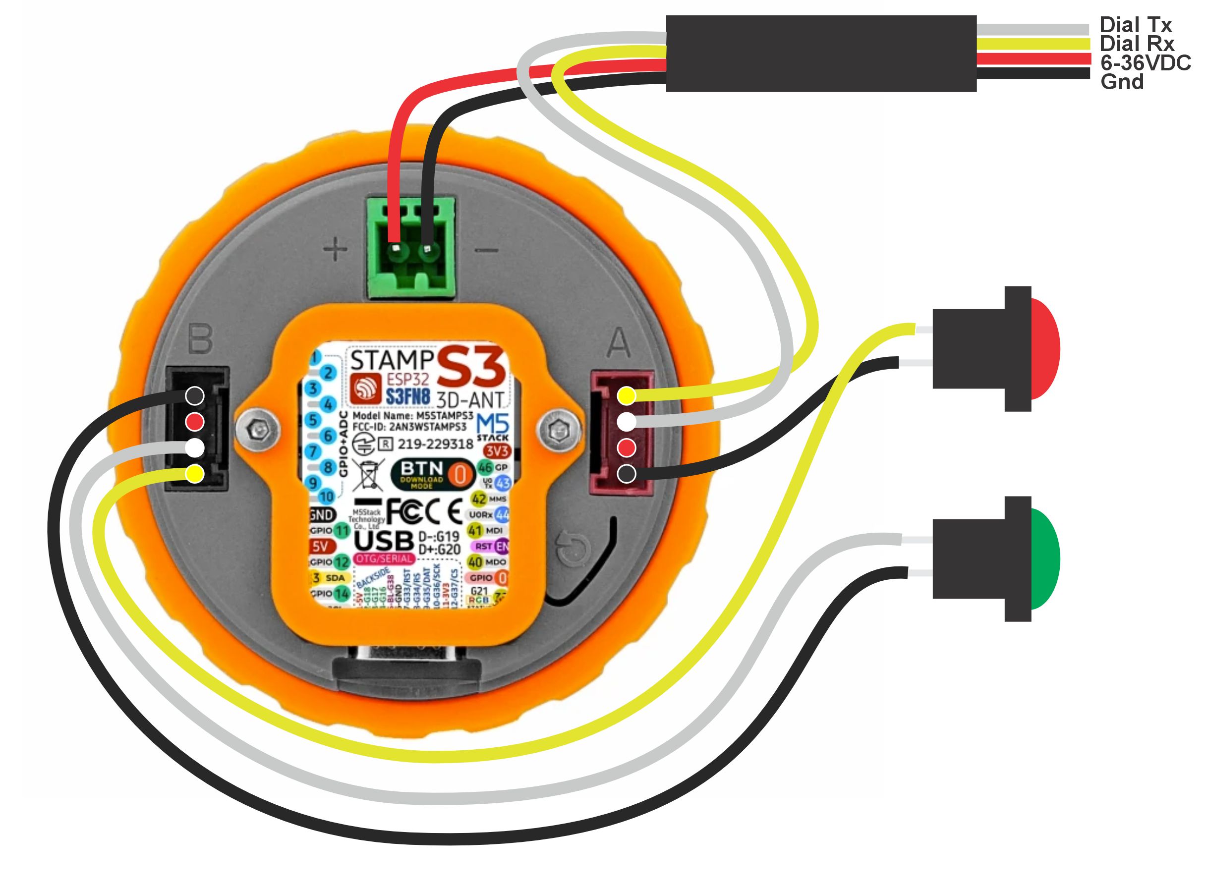
*NOTE: The above “NEW” wiring plan was created based on invaluable help from @Keith_H — Thank you, sir! Keith is a “DIY Down Under” retired developer. Super helpful!!!
I am now re-wiring my pendant and doing the firmware things, and will report back!
UPDATE: OK, good news, and some not good news:
Good news: The proposed “NEW wiring schematic” shown above seems to be correct. The firmware builds succeeded for both the Jackpot and the pendant. The buttons have their “red” and “green” function happening correctly.
Not good news: Despite the magnets not causing issues previously, after I readjusted the wiring to suit the new schematic, it seems (at least currently this is my working theory) that somehow the magnets started causing the pendant to disconnect. It would often say “N/C” (Not connected) and yet then later, after anywhere from 10-30 seconds, suddenly switch to saying “Idle” — and work for a while. Eventually I noticed that when it said “Idle” and I would move it from not being on the new cradle, to being placed in the new cradle, it would lose its connection to the Jackpot. I have removed the case bottom that has 8 magnets, and replaced it with the case bottom that has no magnets, and it’s working again. I will do some checks to verify that it works flawlessly without magnets, and try to confirm that the magnets cause the issue. If they do indeed cause the issue, I will need to redesign for a “friction” fit or find some other way to securely keep the pendant in cradle. More on this in the future, hopefully soon.
1 Like