Having the pendant via WiFi defeats the purpose for the pause/stop button. Not much different than the tablet interface with a touchscreen.
Im waiting 4 the 7" elecrow touchscreen
Having the pendant via WiFi defeats the purpose for the pause/stop button. Not much different than the tablet interface with a touchscreen.
Im waiting 4 the 7" elecrow touchscreen
I have one sitting here, have not plugged it in yet.
The code is ready?
I doubt i would downgrade from my 15.6" touchscreen kiosk or the surface pro 3’ but the pendant looks interesting
When I built my fluiddial I think I remember that there was a few different firmware versions for wired/wireless. And I also think I remember something saying that if you connect the jackpot to fluiddial via WiFi that the jackpot can’t then connect to your home WiFi at the same time. I’ll look again to confirm though.
platformio.ini file
upload_flags=--no-stubDownload Mode
To enter download mode, hold the G0 button on the StampS3 before powering on, and release it after
SOURCE
To add to this. I had to hold the button down the WHOLE time it was writing to the dial.
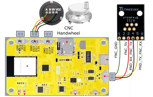
Hey all, first of all thanks for such a great writeup! I built the CYD Dial pendant using this wiring which is pretty straight forward. This is slightly different than this tutorial however specifically the directions show only UART1 changes like this vs the UAR2 referenced above, as well as a different baud rate:
From the documentation:
uart1:
 txd_pin: gpio.25
 rxd_pin: gpio.27
 rts_pin: NO_PIN
 cts_pin: NO_PIN
 baud: 1000000
 mode: 8N1

uart_channel1:
 report_interval_ms: 75
 uart_num: 1
My settings:
uart1:
  txd_pin: gpio.14
  rxd_pin: gpio.13
  rts_pin: NO_PIN
  baud: 1000000
  mode: 8N1

uart_channel1:
 report_interval_ms: 75
 uart_num: 1
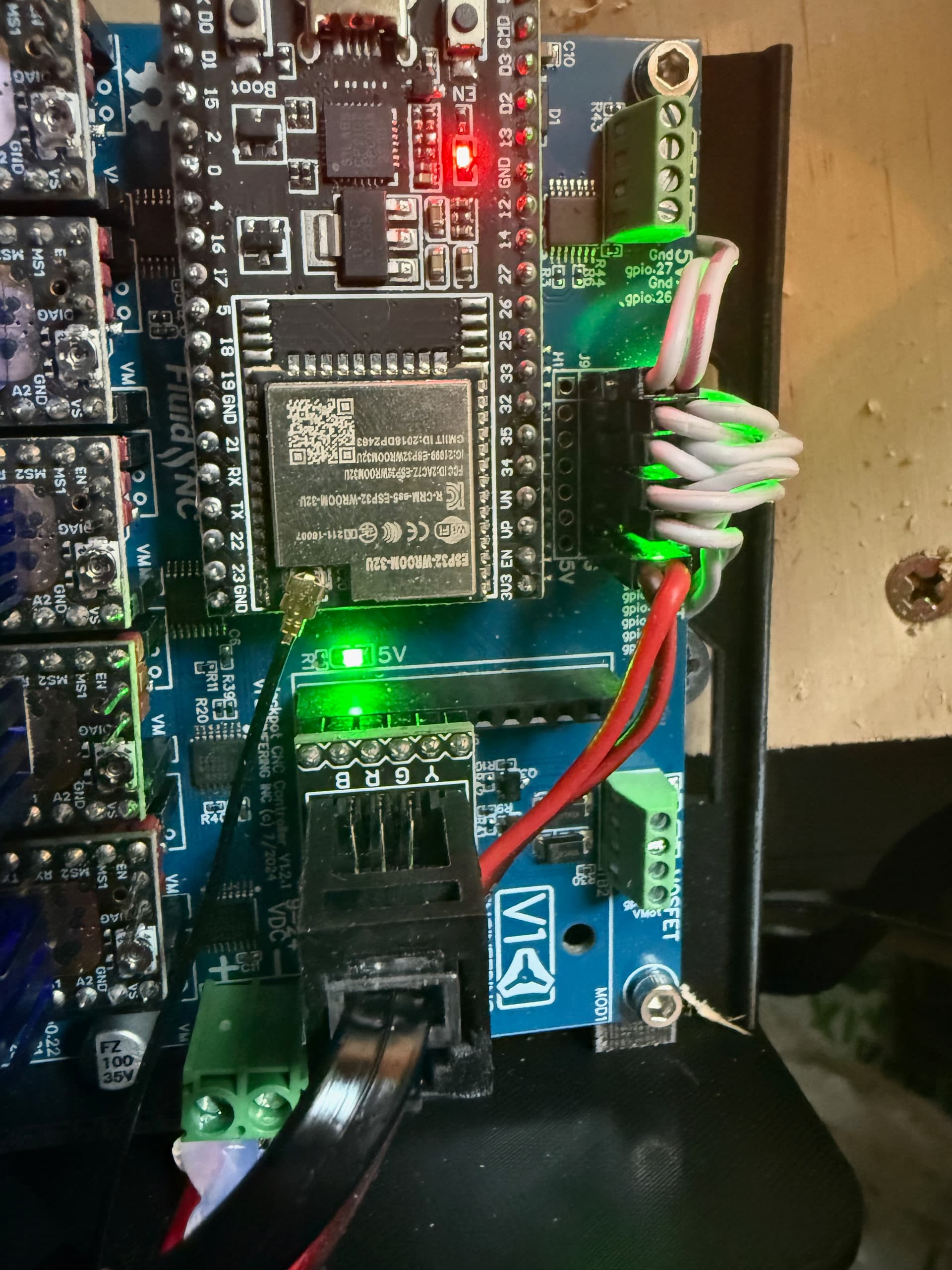
I just cannot get it to connect I have it connected like this as per the documentation, I have power hooked up to position 1 and 3 for power (Ground,5V) then I have messed with TX and RX with no luck (switching back and forth).
Has anyone gotten the Jackpot, MPCNC and the CYD Pendant working that may have some pointers? It turns on great but does not connect…
Lastly has anyone built both, the CYD one is Ok so far but a bit slow, I wonder if th M5 one is better/worse for most.
Thanks!
These are my settings for the M5 dial.
uart1:
  txd_pin: gpio.0
  rxd_pin: gpio.4
  rts_pin: NO_PIN
  baud: 115200
  mode: 8N1

uart2:
  txd_pin: gpio.14
  rxd_pin: gpio.13
  rts_pin: NO_PIN
  cts_pin: NO_PIN
  baud: 1000000
  mode: 8N1

uart_channel2:
  uart_num: 2
  report_interval_ms: 75
My understanding is that UART 1 is already in use, and for a pendant on a Jackpot you need to be using UART 2. See the post above in which Britt shared with you his settings. Note that if you edited your UART 1 settings then you would need to put them back to how they were and add additional settings for UART 2.
True. This needs to be on UART 2.
This will work, however you have no ESD protection and you’re using direct IO to the ESP-32. Be prepared to replace ESP-32s as you will blow the GPIO regularly with this setup.
There is supplemental ESD protection on the kits Bart Sells. There’s a reason the official adapter doesn’t use a breakout as you have done.
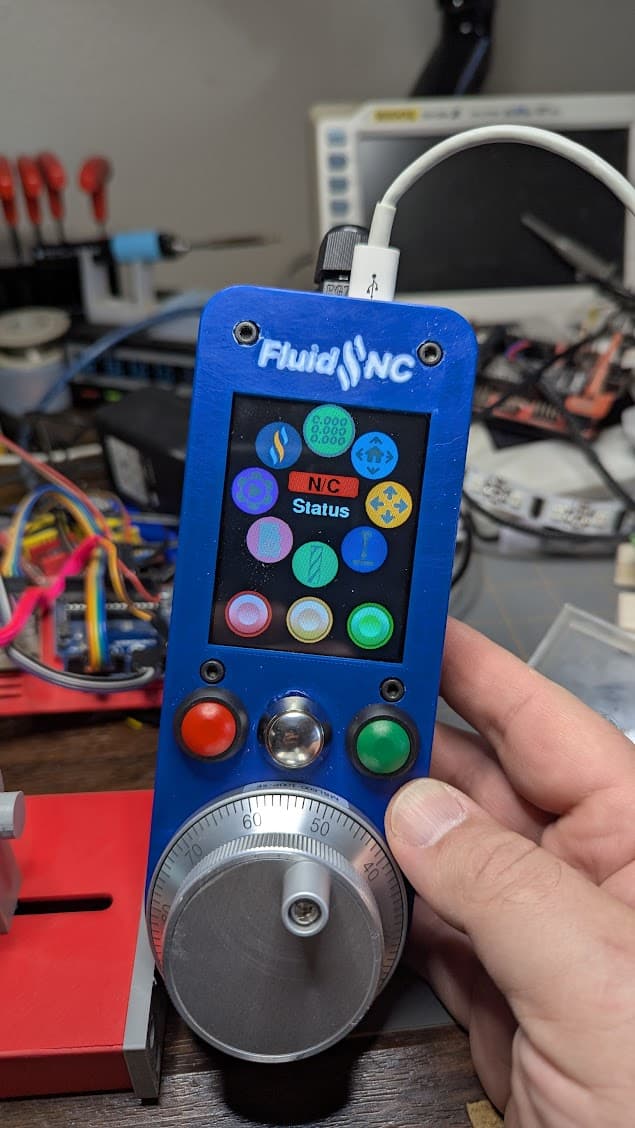
I like my Fluid Dial…but the screen on the M5Dial is a bit small for my taste.
So I also ordered bits for the CYD version. I wasn’t expecting the encoder wheel until Monday - I was thinking about building it up with just a normal rotary encoder to tide me over…but surprise USPS got the nice encoder to me yesterday.
It does take a change in the code now to get the orientation like this…but I really like the feel with the heavy encoder at the bottom - and it made it easier to install the cable gland I had on hand compared to mounting it on the curved end. And I think I like the feel better with the encoder on the bottom.
Thought I had it ready to go and just hooked it to my machine…only to discover there’s one fairly major difference between the M5 Dial and the CYD that I missed.
The M5Dial has it’s own voltage regulation so it’s wired to Vmot on the jackpot in all the examples I saw. The CYD…does not. Whoops.
I haven’t opened it up yet to see how bad the damage is but based on the smell I’m pretty sure I need a new CYD entirely.
And now that I think about I’m thinking it would probably be better to run the M5 off of the 5v line than the Vmot since I assume Vmot is the motor voltage line…so may be noisier. Or is there a reason I’m missing why I see it wired that way in other examples on this thread?
@MakerJim - what’s the current consensus on ESD protection - I read through a few of the older threads and there didn’t seem to be any final call. I saw a good bit of criticism of the protection provided by the official breakout from Bart - but no final suggestion on a better option. It also sounds like the biggest danger is with attaching/detaching the dial - but I plan on keeping mine connected full time so not sure how much I need to worry. I’m not a fan of RJ-11 or 45 for the connection and am fine with it being hardwired…so I don’t like the idea of buying the kit but not using most of it…and don’t’ want to build the circuit from scratch if it’s not very effective as those other threads suggested.
Bummer!
Here’s my opinion, which almost certainly doesn’t qualify as concensus:
You need to have ESD protection.
It’s debatable how good the built in protection in Bart’s module is, but that’s way better than nothing.
You really don’t want to run 5v power over long small gauge wire runs. You want the DC-DC converter in your pendant and to run VMOT to power the pendant.
Jackpot 5V regulator isn’t sized for driving lots of peripherals this way, either.
You can likely get away with running the CYD off 5V , particularly if your CYD is a 3.3V device with headroom in the internal regulator. It isn’t a good idea, though.
I’ve played around with a better circut, but not really happy.
ESD isn’t just plug/unplug and handling. It is also induced by things like moving a cable set around in a charged environment. Like that you find on your machine.
All that said. you can replace an ESP-32 for $10. I’ve replaced 2 now that have been blown by various mishaps.
FWIW, the two halves (PCBs) of the starter kit are sold separately on the Elecrow store.
But one of the two is/was out of stock
I didn’t think about the length of the run much…my wire was listed as 30’ on amazon but I got just under 6’ so that’s all I’m using. But is is small enough gauge I can’t even find a voltage drop calculator that would accommodate it…and I doubt any of my gear can measure the resistance well enough for me to calculate it. But that does make sense.
And - I haven’t looked at the specifics of the jackpot 5v regulator either. I do have plenty of regulators on hand from other projects so it wouldn’t be hard to add one to the CYD.
I haven’t looked at the current draw of either the M5 or CYD - (just assumed that was considered when they were designed. I’ll have to do a little digging while waiting on my new board…or take some measurements when it gets here.
Fair enough - and I do live in a hot dry climate (desert) though oddly enough I’ve generally found ESD less of an issue here than where I used to live in Ohio. And as you pointed out ESP-32’s are cheap and I have several in my parts bin so I wasn’t too scared of the possibility of having to replace one. Replacing the stamp on the M5 worried me more since I don’t have any spares…and the CYD worries me more since it’s fully integrated - and replacing the ESP module on it is probably more work than it’s worth.
And the half I need is the half that’s sold out of course (and even than I’d bypass the RJ-11 connector) wish I’d known to check a few days ago as I just ordered one of Bart’s 2 axis controllers for a future zenXY. Would have checked if it was in stock.
Thanks @MakerJim @Britt @DougJoseph appreciate the response, I was away so just getting back now. So I was following the guide which shows this wiring like this
Are you saying I should connect to the VMot connector vs the 5v connector? Note I am talking the CYD here not the M5.
Thanks again, I will otherwise try these settings tonight.
You should create a new forum topic for your build. I’ll go look at the CYD specs again, then reply hopefully in your new thread. Copying your latest post to the new thread would be a good start.
Just an update on this - there is now a web installer for the dial firmware for both m5dial and using a CYD and encoder.
Very cool. After my m5 dial failed I’m giving the CYD version a go.