aww. Bummer! ![]()
Success!
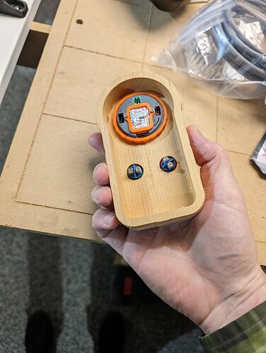
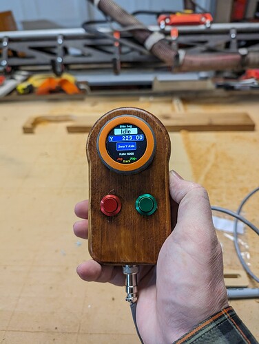
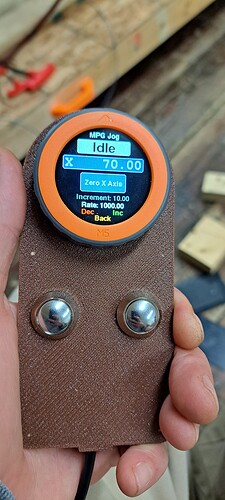
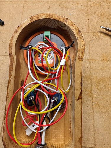
Why 3D print when you have a cnc! Made the enclosure out of a piece of mystery wood out of the scrap bin!
Probably cedar from the smell, stained it with some walnut stain+polyurethane-in-1 stuff. Color 16mm aluminum buttons off Amazon, $6 apiece so not super cheap. Nice though! Removeable 4 prong plug and 8 feet of shielded cable from Vetco electronics.
The last hurdle was the (“dreaded” as someone put it) N/C no connection status.
My issues:
-
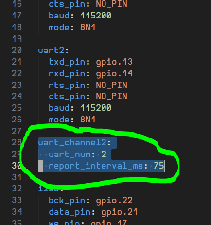
Forgot this block in config.yml! I just put in the uart2 definition as highlighted previously, but not the uart_channel2 block.
-
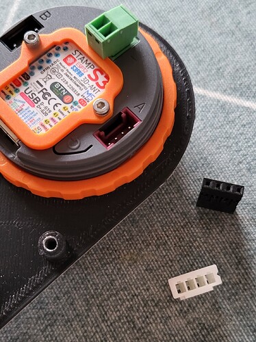
The trimmed down JST connectors weren’t fully seated in the A and B ports.
-
This highly important knowledge:
I had RX to RX. Oops. I did try swapping at first but my jst plugs weren’t fully seated yet.
I see a very occasional negative number pop up for machine location, so my wiring may be a little flaky (too long?) But functionally everything works great.
I prefer having this as a sidekick to the WebUI, as sometimes i had weird network issues in AP mode that required power cycling; once during a run I couldnt access the webui, which was not ideal.
I don’t love that the E-stop function on the pendant causes everything to come crashing down; glad I tested it! Need to investigate “door mode” which sounds more like what I want: stop movement and retract Z a bit.
I do love being able to “sneak up” on a jog location when setting a zero, with the buttons or dial, without accidentally fat fingering the webui touch screen interface jog thingy.
This looks awesome. Congratulations!
Regarding the missed bit in the config file…
It looks like I malformed my documentation! It may be too late for me to fix the post that has the image attached but I could re-edit and re-post it. Ugh.
Thank you for the updated instructions. Greatly appreciated.
Your wood pendant looks really nice. Once everything is up and running I plan to make one as well.
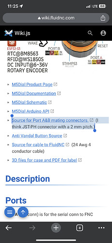
Ah, I had the same issue… In the MD5Dial Pendant wiki they say it are JST-PH connectors (2mm pin distance). Still waiting on mine, so I cannot verify.
From the Wiki:
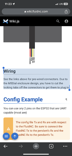
Note part about snipping off the locking tabs.
Wiring
See the links above for pre-wired connectors. Due to the M5Dial enclosure design, you have to cut the locking tabs off the connectors to get them to plug in.
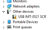
Hi fellow Doug, I have gotten to the part where I am trying to upload the firmware to the dial using your excellent instructions and have run into an error where it seems VS doesn’t know how to connect to it. Do I need to install a driver for this first? I don’t find a COM port listed in device manager.
All up and running. Soo nice having this. I was having a lot of trouble using the tablet screen pressing the right stuff. This thing just feels much more intuitive. Using a USB plugin at the controller I can quickly disconnect the whole thing. Will be swapping that out for some GX16-4 connector soon.
Thanks again to @DougJoseph and @coinbird for the help ![]()
Hmm. While there is a driver associated with the Jackpot board, I am not aware of one being required for the M5 Dial.
The following is copied and pasted from the wiki. Maybe it will help?
FAQ
- Firmware won’t upload.
- Sometimes it gets into a funk and needs a manual bootloader activation. This usually happens if the code is continuously rebooting or stuck in a tight loop.
- Hold the Button on the M5Stamp, under the label. I removed the label to make it easier.
- Click the grey M5Dial reset button. Lower right corner of back
- Release the M5Stamp button.
- Now try to upload the firmware.
- If it uploads, you need to click the grey button again to enter run mode again.
Check that you have a data usb and not a charge usb?
Got it. I tried disconnecting the USB cable at the computer and re-connecting it and that didn’t work. I then disconnected it from the M5 and verified it was a data cable and when I plugged it back in to the dial I noticed windows setting up the device. Tried uploading it again and …Success… Maybe I didn’t have it fully inserted the first time. Anyway I have it looking like it should now. Thanks.
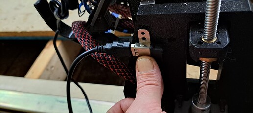
As Doug noted you will need to trim the tabs, as in the two little strips on the side, which will face outwards. Don’t have a great pic but this is what they look like plugged in. It’s a tight fit so make sure they are fully seated.
Need clean up the rats nest, but still not sure my connection is 100% because of the negative position “blips.” Wishfully thinking it’s just a bug, but i will likely go back and ensure the solder joints are all 100%. Have any of you with working pendants seen that perchance?
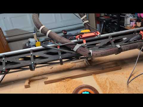
Video, if you look closely, you’ll see the random numbers pop up once or twice near the end. Also happens when not moving, so might need to shorten my cable or something. It is shielded cable. Random audio accidental plug for my fave radio station, king fm ![]()
Your pioneering and getting this to work on the Jackpot was invaluable, thank you for leading the charge!
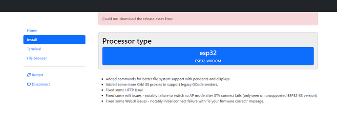
I saw that too (3.7.13 gone missing) but the newest 3.7.14 test version also works.
Yes, this is what I ended up using.
Offtopic:
Do you guys use soft limits to prevent crashing into your endstops. or does that cause issues when you zero out at a job start? It’s been over a year since I’ve run the lowrider. I need some basic refreshers I think.
I have both hard and soft limits enabled on all my axes. You may need to fiddle with your probe code so the Z limit doesn’t get violated and cause an alarm.
For example my z travel soft limit is 75, so my G38.2 code has a Z-74.9 travel specified.
Great, Thank you.
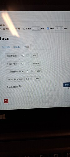
Using the probing on the Pendant confuses me. I thought I would need to match the settings the pendant to the settings in the webui config but this makes my z run upwards instead of down towards the plate. It seems to be the max travel that does it. The pendant requires a negative number while the webui requires a positive number? Why are these different from each other?
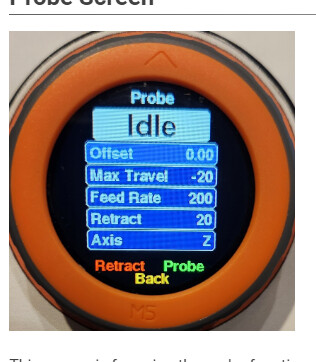
I’m doing the same thing. Exactly what he stipulated here, except my max travel in Z is a longer distance because I have the taller YZ plates.
As for the web user interface calling for a positive number for probe travel distance/target distance, while the pendant calls for a negative number, I would imagine it’s simply because the two interfaces were designed at different times, and possibly even by different people. I would think that one or the other is doing some kind of an inversion in order to make it work.
