Finally doing an upgrade - original MPCNC to LR4

I hate those spiral things…the “Chinese finger trap” style expandable ones are a bit better…but always start to fray on me way too much and heat shrink can only hide so many sins. And when you need to branch off they don’t help much at all.

I really like the self wrapping fabric style of sleeving that Prusa uses (or at least used when I got my MK3s) I finally found some on Amazon but it was too rich for my blood. Still, may pick some up in teh future to go over the lacing if I find I don’t keep messing with things on the LR4.

Thanks! That was a fun build. I had hoped to use it to explore an abandoned date farm near me - but the ply was both heavy and weak making for very poor performance and major damage in even mild crashes.

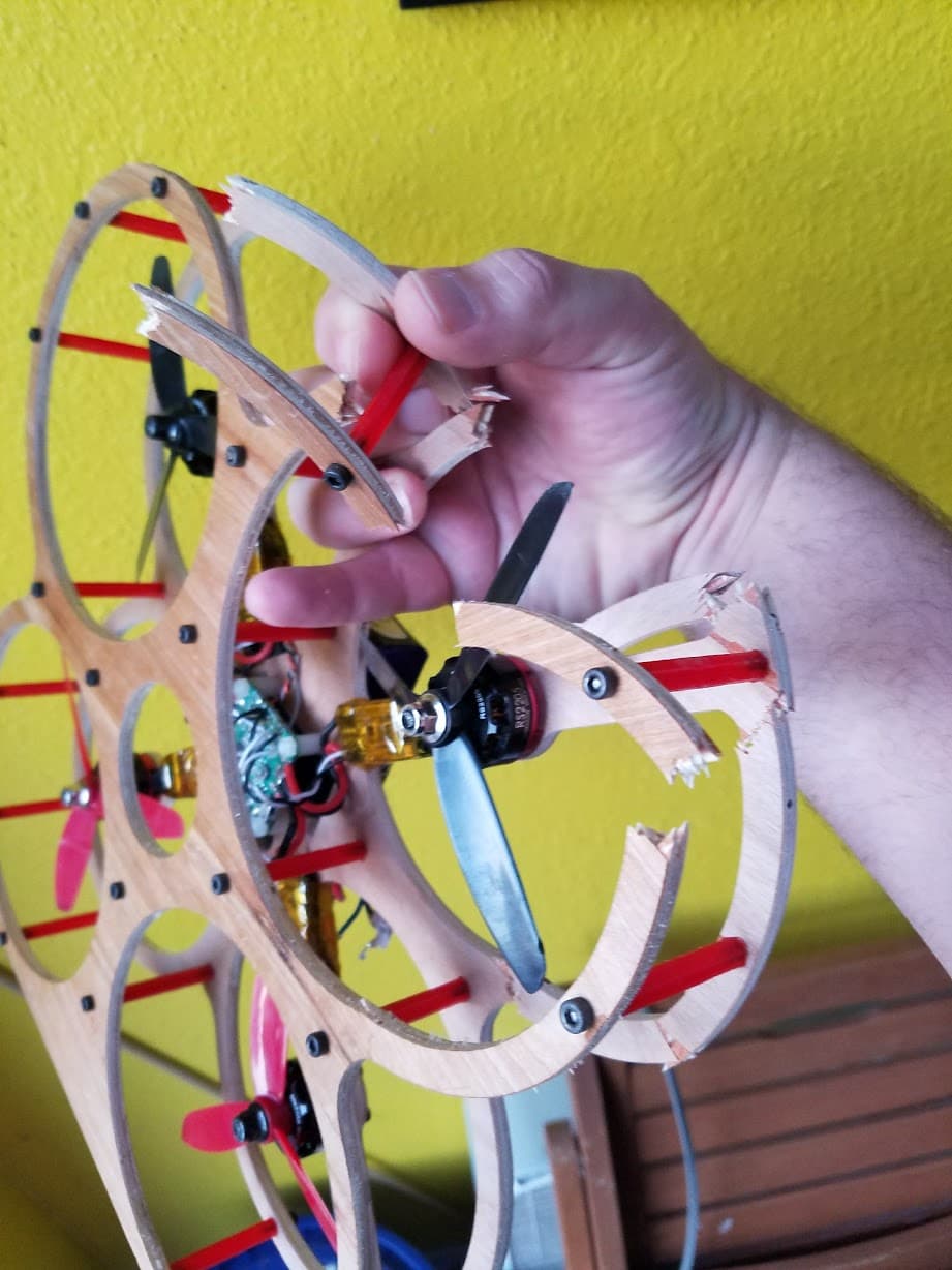
Between crashes and issues with my oversized MPCNC I went through a lot of frames with minimal actual flying:

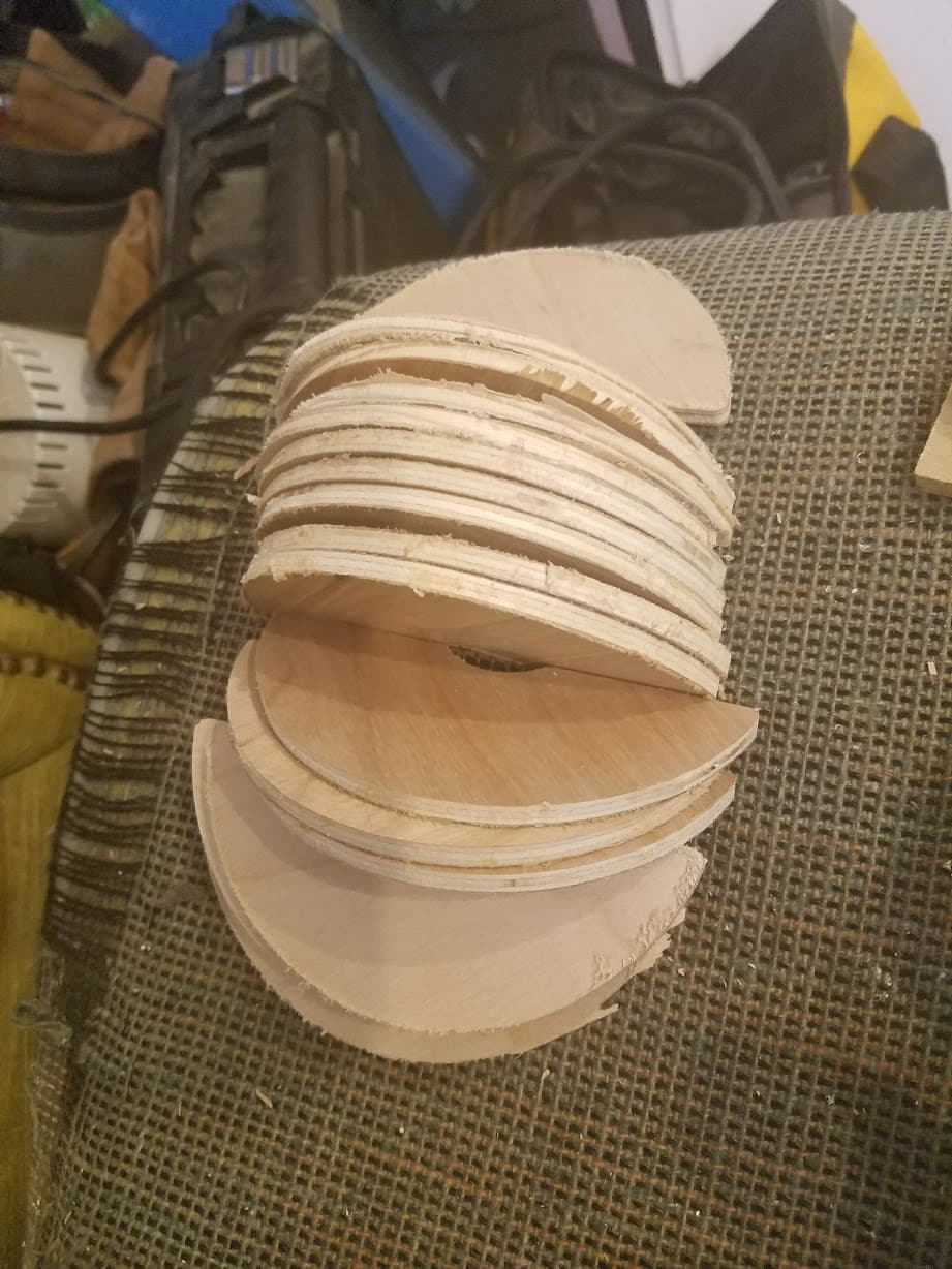
I actually just threw out a big stack of circles from the top cuts…my girlfriend who’s been pushing me hard to throw more stuff out actually liked them enough she wanted to keep them…but relented and accepted she probably wouldn’t do anything with them either. And if she did want some I could just make her new ones.

I did a bunch of tests to try and find another material that would work. I know it’s workable with CF plate - but the cost for that is crazy high and I couldn’t bring myself to waste that much expensive CF. I tried sheets of PVC but they were too flimsy - so I tried one sheet of polycarbonate and one of PVC:

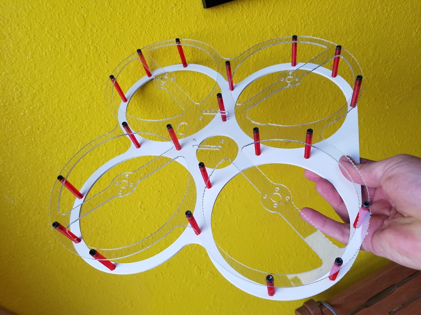
But that made it worse because now it was both fragile AND flimsy - the PC wasn’t stiff enough so the frame had major vibration issues and when it crashed it still broke. The PVC help up fine…but it was just too soft and flexible.

I played with chemically welding some pieces to it to stiffen it but that didn’t work well either.

So I started experimenting with different laminates. I knew I could use fiberglass on the light ply but even the bare ply was heavier than I wanted. I started doing experiments with light glass over foam board:

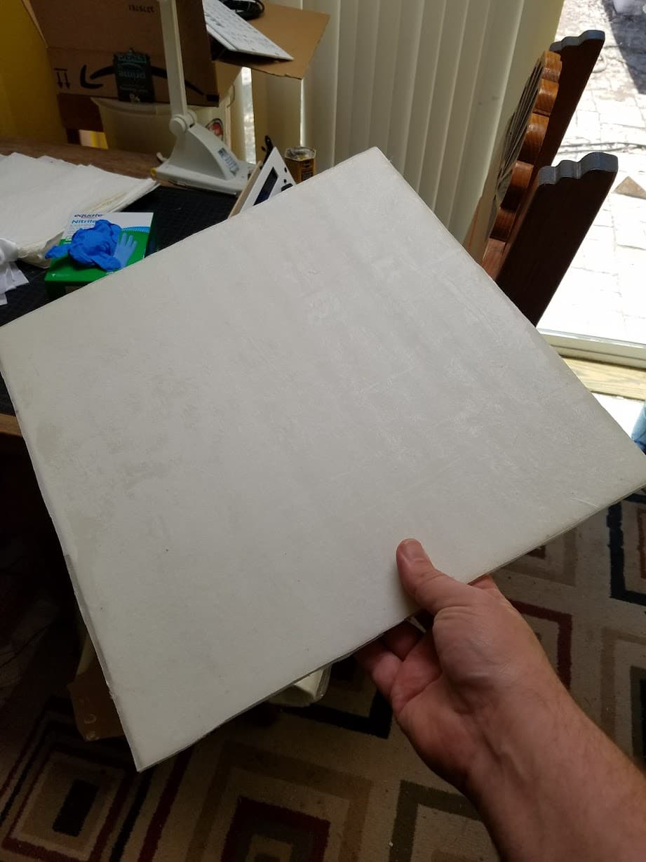
But…the light glass was more expensive than I wanted and it started getting heavy again.

I had started to do more testing to find a DIY composite material that was cheap and light - peeling the paper off foambaord and using paper sold for protecting floors during construction seemed to have potential. And I was about to start cutting up old jeans to laminate into panels to try ( I thought a jeans copter would be pretty cool even if it wasn’t practical) but that all got set aside when my wife suddenly passed away. I actually just threw out a lot of the test pieces I had made as I cleaned out the old shop.

Maybe once the LR4 is up and going (getting really close!) I’ll dust some of those ideas off and start experimenting to find a light and cheap DIY composite again…

2 Likes

If you have any of the plywood frames left, paint it in tightbond III and see if it gets at least a little more robust to damage…

Sadly all the wooden frames wound up in the burn pit years ago, I still have the design files in OnShape: Onshape

And I still have more of that ply I think, and all the motors/electronics are still here. So…maybe once this LR4 is done.

Speaking of which…got the other side finished and assembled it all. That belt into the YZ min was way worse than I expected :scream: But…I got it in there.

Mounted the lowrider box and wired it up:

Still have to clean up the wiring…but will do some tests first:

The X belt needs to be adjusted a bit too - I made it a little too long and the tensioner can’t quite take it up…still it’s enough to see it move:

Of course first I powered it over USB and tested all the endstops to confirm they were functional. Once that passed I gave it real power and was happy to see X and Z both moved. X was initially backwards and my first attempt to home it took off in the wrong direction - thankfully I thought to hit the endstop manually before it crashed.

So, powered down, flipped the connection on X and powered back up for that little video.

Hopefully tomorrow I’ll have time to duck out to the garage and mount it up and see if Y works as well as X/Z do…then I can dig in on cleaning up the wires in the control box.

Guess there is a VERY good chance I’ll be making some chips this weekend…or at least drawing with a pen.

Though - it’s also 95 in the garage right now at 9:50PM so that’s not great. Definitely think I’ll be unmounting it and storing it inside when I’m not actively using it, and running the garage AC when I am out there using it. And will probably have to fire that garage AC up tomorrow as soon as I get home from work!

5 Likes

Well, I did duck out to the garage last night. Good news is the AC out there works pretty well, took it from 97 down to 80 in about 30 minutes - could have gone cooler but 80 was comfortable enough to work in and I’d rather not dump money into running the AC more than I have to especially since it’s still March!

And I was able to test my Y axis…one motor was reversed - so initially it was fighting against itself - but that was easy to correct. I also took advantage of the extra space on the bench to confirm a few squareness checks on my build and it all looks great. And it looks like I got my initial Z endspot positions pretty close as an initial Z home resulted in barely 1mm difference measuring the bottom plate to table. So all was looking pretty good!

But…I still don’t have it actually mounted to the table. You may remember I mentioned awhile back that I decided to go a little wider than my initial plan. And I haven’t cut my Y rail yet…I had considered leaving the Y rail as long as possible but didn’t realize that it would interfere with the belt mounts as I hadn’t looked that closely at how the belt and rail mount.

So I had to cut the Y rail down a bit more afterall…which worked…except I took the wrong number from the calculator :roll_eyes: thankfully I took the table size instead of the rail size so I cut it too long…but it still confused me when I went to put it on the table and it was too long. So I get to cut that again.

A few notes I’d suggest to the docs for future builders - an image showing the overall machine with all of the axes clearly labeled would really help. I found one or two posted in the forums but it would be nice to add one to the docs. (Note - I’ve already forked the docs so I can submit some edits - but not sure when I’ll have time to look at that, I’m not great at writing docs, and my main computer suddenly stopped outputting anything to it’s attached screen this morning…so I’m guessing someone else will likely make an update like that before I can!)

Also a few more photos showing how the belt mounts go in relation to the rail and how to position the belt mounts on the other side as well would be helpful.

Anyway - after my measurement snafu I didn’t feel like cutting the rail again…so I started debating just making the machine a bit longer still…but then I’d have to inside to the calculator and mess around…plus I’m still wary of the back of my table being unsupported. And final straw for the night - I put my long straightedge down on the table - and sure enough there’s a slight sag in the middle already.

Sigh - ok…not going to mount it until the table is really done done. Tonight or tomorrow I’ll run to the store for a little more wood and I’ll finish adding a support grid under the tabletop and a support under the cantilevered part of the top. Just debating if I want to use 1/2" MDF strips like the grid…or if I can just put a 2x6 under there with a few braces and which will be stiffer long term.

I’m not in a rush…but being this close it’s hard to not rush :smiley: But I want this nice this time so stepping back and taking my time is usually the best decision!

3 Likes

Yeah I am right there is the second version of the doc updates. I have all the pictures for the wiring, next is belts.

2 Likes

If you’re actively working on docs…one thing I did a little differently was instead of installing the endstops on the YZ plates as instructed I just taped them roughly in place in the openings so they weren’t sticking out but still had enough wire to go into final position. That way I had no risk of damaging them as I completed assembly - and was able to easily add the two screws to them at the very end.

I also found using a bit of filament as a fish wire to pull the endstop wires through the last passage on the YZ plate helpful.

A few other thoughts on the docs -
It jumps right to cutting strut plates after squaring. There are links to the basic setup pages - but it may be better to explicitly suggest doing some initial tests with a pen before jumping into making plates.

There isn’t much info on how to add a pen to the LR4. Some suggestions on how to do that may be helpful for new builders.

Also - the last photo after making permanent plates showing how to check that the heel and toe measurements shows the second measurement being made across the feet - which the earlier instructions on doing an initial heel/toe measurements warns not to do since the feet are separate pieces from the plates.

Hope the feedback helps, and I did get mkdocs running here on my notebook so if I get time I’ll see if I can try and contribute directly once my machine is up and going.

2 Likes

Nice, I will add something along those lines.

This is the reason for my second build to update the docs. They were written mostly for people upgrading and now we have clearly moved on to new builders again.

I just made the pen mount last week I still need to add it to printables.

3 Likes

Well, it’s alive!

I didn’t even bother to square it yet…just did some rough checks and confirmed it was moving sanely in all directions…then strapped on the closest writing implement I had and gave it a go.

Honestly…went better than I expected. Between not being squared and a zip tied pencil which was moving all around and wore down as it went I consider this a huge success. Far better than the first test I did on my old MPCNC at least.

Biggest problem was I couldn’t upload gcode from my ipad:

I don’t expect that to be part of my regular workflow though so it doesn’t worry me…I was able to use my android phone to upload the crown code without having to go back inside to my computer.

The bench is looking better too:

I added a 1" strip of poplar across the front to protect the particle board. Then mounted some outlets for power…and added some supports where the LR mounts:

I still plan on adding more MDF strips under the main area under the LR to help stabilize it and keep it flat. But I ran out of screws and time.

Hopefully tomorrow I can find time to do some wiring cleanup, dial in the squaring adjustments…and if all goes well maybe I’ll even get to strap the router on. Though getting the bench back in place is my top priority so I don’t have to park outside again :smiley:

I do have some magnets coming tomorrow for @DougJoseph 's kinematic mount for the pen, and for my old laser (which it looks like I’ll have to design a new mount for.) And an M5 dial will be here Monday which is the last part I need for a pendant.

8 Likes

Congrats on the exciting progress!!

That looks like a great table. Are you going to put it on casters? It looks like 6 would work well. Harbor freight has some cheap ones.

I considered it strongly…I realized I’d have to account for them when I built it if I didn’t want it to wind up taller than I hoped. And decided that realistically I’m almost never going to move it once it’s done so probably best not to bother. (Plus I’m cheap and casters cost money)

I did have a set of “casters” on hand…but they’re really designed to mount to a sheet of plywood to make a base for something. They’re nicer than normal casters as they have a lever design and drop down onto solid stops when “parked” so great for equipment. I added them to the bench last weekend and they did help it move around really easily. But…the design of them wasn’t ideal. They stick out about 6" in front with a big locking lever that lifts/drops the table. And that was a problem. Because I park right next to the bench and my daughter and girlfriend both have to walk in front of the bench to get in and out of my car. And both of them are notorious for tripping over just about any thing.

So…even though they were bright orange and hard to miss I knew if I left them on there one or both of them would trip - probably repeatedly - and that would not end well for me.

And there are still some things I’m not overjoyed with about this bench. So I may build another in a year or two. I’d build the top more like Ryan’s table plans making a proper torsion box and grid which I’d then mount onto the legs…instead of my current approach of putting the top on the legs and then reinforcing it. I can tell already this top isn’t as flat as I’d hoped and is getting worse as it sits.

And once I add a shelf underneath I’m sure I’ll have some thoughts on how to optimize the space under it better in the future.

I’ve always hated doing things more than once. I really like to plan, test in CAD if I can (and I did for the bench) and then just build something once the way I want it. But over the years I’ve come to accept that doing something more than once is usually the only way to get it the way I REALLY want it. The old bench I cut up for storage was my first and it was really quick and dirty but worked at the time…by the time I built the table for my old MPCNC I’d learned a lot and avoided a lot of mistakes. But still made a bunch of new mistakes. Now I’ve tried to avoid those mistakes on this bench but again learned a few new ones I can now avoid next time :smiley:

But - now time to go do some squaring and tests!

1 Like

Another life lesson I’ve really struggled to accept long after I learned it.

Sometimes even when you’re feeling productive and effective it’s really best to step back.

Last night after that first crown I REALLY wanted to push on. But, I needed to spend some time with my GF so I had to stop. I struggled with that at the time because while I love her and love spending time with her - I was feeling so accomplished with the machine I REALLY REALLY didn’t want to stop.

But I was also getting tired and sloppy so it’s probably for the best that I did.

I just went out and ran a squareness check. X/Y was within 1/16" - which is well within the measurement error measuring by myself with the tape I had available. (I have tape that’s better for this kind of check here somewhere but no clue where it went in the move…heck it might still be hanging in my old laundry room now that I think about it.) So I’m very happy with that.

Thought about doing a Z…but that seems easiest with the touch probe and to do that right I pretty much need to mount the router…which I’m itching to do…but still want to do a bit more testing first.

So…ok…let’s strap a proper marker on. Fresh new sharpie and:

I’ll take that for sure!

Still a terrible mount for the sharpie that lets it move way too much. And a sharpie is a pretty blunt instrument. But…this is probably better than I was ever able to get with my old MPCNC and a sharpie even with a nicer sharpie mount!

Hmm…how about a little ruler test:

Ok, i didn’t quite realize just how big it would be and which direction was which yet so had to “extend” my paper…and the sharpie shifted and lost contact at one point. but overall that’s looking pretty good. Need to try again with a better mount and a more precise writing instrument.

Did some corner marks and connected them to find my full working area:

Exactly as expected - 21" x 34.25". Would have liked to have gotten 24" in X but then my workbench would have stuck out too far. And 20"x30" sheets of foam board are my favorite thing to work with so 21" should be sufficient.

I was a bit surprised at just how much “wasted” space there is at Y Max. Part of that is due to me not mounting things right to the edge of the table. But there’s over 14" of open space there. I wasn’t quite expecting that and now I’m debating what I can do with that space. Maybe a little stand for my iPad…

I’m also still struggling to get used to the new coordinates…my old MPCNC was setup with 0,0 in the lower left corner as I faced the machine and X+ to the right and Y+ away from me. Now 0,0 is in the lower right from where I’ll usually stand and X+ is away from me and Y+ is to my left. I think I can get used to this…just means shifting things around a bit in estlcam and thinking a bit differently. Which is probably easier than trying to make the machine work with coordinates the way I’m used to.

I figure it’s probably not too hard to reconfigure FluidNC to swap X/Y…but 0,0 would still be to the lower right since that’s where it needs to home. Making it home to the lower left would require mechanical changes I’m really not feeling like dealing with. And while I’m VERY new to FluidNC I can’t think of a good reliable way to have it home to 0,0 in the current position but then consider the current YMax/XMin to be the real 0,0. It may be possible…but I’d rather see if my brain can rewire than deal with trying to change the machine. Maybe at a future date if I’m feeling frisky.

Alright. I’m really happy. And still waiting on magnets for my proper pen mount.

So…time to go cleanup some wiring, strap on the new router, and do a little CAM - if I can make something for my GF by the end of today it will really help make up for all the time I’ve spent on this the last week!

3 Likes

The mechanical changes are pretty minor, there are locations for the endstops already, and the changes have been made by Doug I think, though it is much easier to just rotate the workspace in Estlcam. The machine does not care where you think X/Y are, so if you have Estlcam in Portrait mode and remember that the bottom left of the screen is the bottom right corner of the CNC, it should be easy. :slight_smile:

Alright, Sunday chores are done so back to the LR4.

Few small issues I’m trying to figure out.

Note - I’m still using Estlcam 11 - if I absolutely have to I can upgrade to 12 but it would be best if I could wait a few weeks before spending the bucks on that since I had to pay two mortgages this week. So some of the setup screen shots aren’t 100% relevant…but I’m working through it.

1st issue - (And this is probably entirely to Ryan still working on the docs.) If you follow the setup instructions on this page: EstlCAM Setup - V1 Engineering Documentation

It has you add startup gcode for probing. But then goes into using a pen and saying to set Z manually. But then when you run it it tries to probe.

I first worked around this by wrapping some aluminum foil around my pen and clipping the ground of my probe to that. It seemed to work. But my drawing occurred a mm or two above the paper. So I decided to just eliminate the probing and removed those lines then redid it just setting the pen to just touch the paper.

But again I got an “air cut”. To do the crown drawing I did above I just pushed the pen down manually after trying a few different homing/zeroing things and deciding I must be missing something. As it sure looks like zero is set at the surface of the paper with the pen just touching so a 1mm “cut” should have the pen in full contact not retracting above the paper. Maybe I’m just not understanding the FluidNC screen correctly when I zero out…

2nd Issue - I can’t figure out the instructions for doing the Z leveling…I’m thinking they’re mostly for the LR3/SKR still? First issue is when I do a probe either from the UI or by entering G38.2 Z0 it doesn’t retract even if the UI has a retract set. 2nd issue when I tried the instructions in the 4th bullet point it gave an error that M114 wasn’t a recognized command - I’m not sure what the equivalent in FluidNC is to report position.

I assume these are the position readouts in FluidNC:

But I’m only seeing what looks like 0.09 difference after probing even though I’m fairly sure (from other manual measurements) that my XMax is about 1mm lower than my XMin.

And if I had got that far I’m confused by “Adjust the Z pulloff in the settings tab.” I assume I adjust one of the two Z pulloffs depending on which motor is higher. But I’m not quite sure which is XMax and which is XMin - I can figure it out with some wire tracing…but…overall these instructions are just still very vague. I had hoped once I was actually working with the machine they’d make more sense but instead I’m looking to do some more research/digging.

That said…I did go ahead and try making something for my girlfriend to help compensate for the time I’m spending…it may have been premature to go throwing it at wood…and I definitely wouldn’t suggest trying this to a 1st timer. But I felt I knew the risks and was ready to do this (despite just having nicked a screw head trying to mark my extents in my old spoil board.)

So as I just hinted I screwed down my old spoil board (which was originally the base for my first build 9 years ago) screwed down a scrap of 1/4" ply I had on hand…then spent an hour trying to remember the best way to convert a STL to a DXF in Fusion only to wind up using tinkercad which “just worked”. And…

I should have measured that piece of scrap instead of just eyeballing it. Oh well, just looks like murder kitty has a bit of a clipped grind on his knife :smiley:

But it worked…it worked wonderously. Way better and easier than I ever experienced with my old machine.

Still need to cleanup the wiring…and figure out how to deal with the power cord on this router…and my vac hose came and I think I just heard USPS drop off those magnets…

But overall I’m really happy - now to do some more reading / research to figure out this Z square adjustment.

4 Likes

Alright - after some research I found @DougJoseph’s videos on squaring/tramming and figured out what I was doing wrong.

The default probe button doesn’t do a retract and neither does the G38.2 command…all the videos I’ve seen of what I thought was a normal probing cycle are using a macro to do a double probe with retract.

So I stole Doug’s code and setup a macro - looks like probing makes more sense now.

I then was also able to do repeated probes at Xmin and Xmax - get the results from the PRB line in the output…average them and find the difference.

Was actually closer than I expected. I was only off by about 0.6 some…(I can’t find my paper I wrote it down on and can’t remember the exact number but it was < 0.7mm difference.

Then I traced the wires to confirm Z on the Xmax was in Z1 and Z on the Xmin was on Z0 - subtracted the difference off my Xmax Z and things looked really good.

The magnets I was waiting on also arrived so I mounted one up to the kinematic mount and hooked up a nice Uniball precise 0.5mm pen and ran a ruler test.

Of course the pen still slipped in my zip ties a little…but other than that results looked great - so I also ran another crown…and it looks darn near perfect:

The problematic parts of the ruler were entirely due to the pen slipping in the zip ties. And I didn’t include a ruler in the photo - but I assure you it matches the marks perfectly. This is far more accuracy than I was ever able to achieve with my old machine!

Oh, and the paint dried on the murder kitty and my girlfriend was excited to place it above our back door:

I may make another though - I realized that the one I saw online a few months ago actually had a notch in the knife so it looked like the cat was taking a slice out of the door frame. Didn’t notice this one didn’t until after it was over the door.

Guess it’s time to start designing a new needle cutter optimized for LR4 mounting :smiley:

8 Likes

Nice! Congrats on more great progress!

2 Likes

This is a good strategy. If you’re feeling motivated to keep going, you can leave on a cliffhanger and have more motivation to return. If you only leave when you are having a bad time (which is also a good time to step back), then you will feel crummy whenever you think about your machine.

3 Likes

My helper finally decided to join in again and we finished reinforcing the back of the table tonight.

Of course my drill batteries both went dead with 3 screws left to do so I had some time to do some cleanup. Started sorting out the wires. Looks like I’m going to have to extend the tiny touch plate and X endstop wires (I made the endstop wires the same length as the touch plate wires assuming the touch plate wires were a suitable length for a full sheet machine.) So can’t quite put a lid on it yet…but at least I have a lot fewer wires over the board.

And I managed to break one of my own endstop wires…I knew 30awg was risky…but I wanted to make it easy for myself to fish though the passages. Honestly I think this was just a bad crimp and it was an easy fix.

Also found I can’t quite push the bench all the way up to the wall or my Y endstop on the Xmax side hits the wall. Guess I should have mounted the machine 1/2" in from the edge. oops.

But it’s all together now and the bench is looking pretty good:

I moved the CO2 laser to under the bench because it’s not really usable right now. I swapped it to a smoothie board and started installing new optics but didn’t have enough room around it to access the mirror mounts and actually get it dialed in so it’s just been collecting dust for a few years. There’s actually a bunch of extrusion next to my bench that I was going to use to build a new motion system for it that I haven’t gotten to yet either. Add in the fact that I don’t have a chiller and buckets of ice don’t last long in the desert - and ventilation was a pain at my old house…and it just became a paperweight. Though - now that it’s in a garage with an outside wall right behind it I may install a vent and finally get it going again…would be nice to have…but project for another day.

I also realized that I actually have room to work on full 1/4 sheets of ply/mdf. My cutting area doesn’t cover a full 2’x4’ but there’s plenty of room for 2’x4’ sheets to fit on the table. So that’s a nice little bonus! And means a 2’x4’ sheet will make a decent spoilboard.

Now to find where the rest of my endmills went and start seeing what this machine will do! The 1 3mm single flute bit I have handy has had a hard life and isn’t in it’s prime anymore. I do have a new 1/4" bit I ordered from Ryan (since at the time I placed my order I was going to use my Dewalt 611 and wasn’t sure if I’d be able to find an 1/8" collet for it) but most of what I want to do would be better with a smaller bit. So need to figure out which box those went in or get an order placed I guess. (I know if I order some the old ones will magically turn up!)

2 Likes

I continue to be blown away by how much better this LR4 is than my original 9 year old MPCNC. I loved my original MPCNC and recommended it to anyone who asked me about it. And I knew it was limited by my choice to make it as big as I did. So I expected to like the LR4. But I didn’t expect to be this happy with it.

Admittedly part of it is the Jackpot board and FluidNC. A number of things I disliked on my MPCNC were directly due to it running Marlin. It was serviceable but for awhile I had been considering switching it to run GRBL…just…GRBL felt very…dated when I used it on some smaller projects. FluidNC has all the things I liked about GRBL and is CNC focused…but updated in ways I really appreciate.

But the new mechanics are also wonderful!

I got home from work and immediately ran a hog out test with @jamiek’s gcode generator. Suggested defaults looked pretty good. The cut was definitely getting a little rougher as it progressed - but again this endmill is pretty old and beat.

Still it all looked acceptable to me so I ran another test starting at 1000 mm/min and going up to 3000mm/min

This time I could definitely see some deflection in the cuts at the highest rates:

I didn’t realize at first that the test also increases the stepover - missed that somehow when setting it up…so I may do more tests to see how stepover affects things. But it looked to me like the 2200 mm/min test was the first that started to show deflection - so I fired up estlcam with some test parts I whipped up in Fusion and gave them a cut at 30mm/sec with a 4.5DOC.

That’s WAY faster than my old machine was capable of…my old machine struggled and was unreliable at 10mm/sec 1.5mmDOC with this same bit.

Test parts came out ok…not spectacular - but they’d be good enough I wouldn’t have felt like I had to do them over if they had been real parts:

I suspect a bigger issue is just how beat this endmill is. I mean…I can see the runout on it from it being being crashed into work several times and having nicked a few fixturing screws.

I also managed to somehow really mess up a quick metric conversion in my head and somehow came up with 20mm for cutting depth on 1/2" stock…oops…sorry spoilboard:

I kind of like how it’s a brand new machine…but this spoil board has 9 years of memories I’m not really to give up yet. Soon I’ll pickup a new sheet for a fresh spoil board I can properly surface…but for now I’m just having some fun.

These test cuts are to see if I need to account for any clearance when I either cut some particle board to make a grid under my table…or make a new case for my modular synth:

The last case I made I used 3D printed mounting rails…but had a hard time accurately drilling the mounting holes manually…and it melted in the heat because of lack of support behind the center rails. Plus my table saw is pretty much beyond hope and getting the box square was a major struggle. This is why I decided to make my Y a few inches longer.

The combo of tabbed top/sides to ease assembly, CNC drilled mounting holes, and a support frame in the middle will hopefully make for a much more accurate and solid case…which will help keep the rails from sagging if it gets left in a hot car again.

But…tonight will probably be a bit of desktop fun.

I’m really liking FluidNC…but what I’m not liking is how if my ipad goes to sleep when it wakes up it looses connection. And then if I reload the page fluidNC won’t bring the UI back up until the job is stopped. Not a fan of that…made it hard to tell what happened at the end of cutting those test parts when I thought the program was over but it suddenly started cutting another set a little further down the Y axis.

The estlcam preview didn’t show that…and loading the code in NC Viewer definitely shows something that was unexpected and not what estlcam’s preview showed…but also wasn’t what actually happened:

No clue where that third pattern came from or why it’s off in the middle of nowhere like that…but that’s also not where it cut…very odd.

Fixed the depth and resaved in estlcam and it looks a lot more sane now:

But the point remains…losing access to the UI during an operation is kind of a bummer…and I don’t really want to change the timeout on my ipad or have to constantly fiddle with it.

So…thankfully an M5 dial arrived last night:

Not sure yet if i want to fire up the MMU and use the nice metal buttons…or just stick with the red/green ones I had on hand for now.

Actually also ordered an encoder dial and a CYB but they’ll take longer to get here…the M5 is pretty neat but the big encoder and CYB seems like it may be a bit nicer of an interface.

Guess I should make that wire actually connect to something now…

8 Likes

Looks great! I think you will really like the M5 pendant. I’ve run jobs that were on the SD card and it is really nice for jogging. The web UI works well however the pendant is handy and it hasn’t went to sleep on me.

2 Likes