Alright, Sunday chores are done so back to the LR4.
Few small issues I’m trying to figure out.
Note - I’m still using Estlcam 11 - if I absolutely have to I can upgrade to 12 but it would be best if I could wait a few weeks before spending the bucks on that since I had to pay two mortgages this week. So some of the setup screen shots aren’t 100% relevant…but I’m working through it.
1st issue - (And this is probably entirely to Ryan still working on the docs.) If you follow the setup instructions on this page: EstlCAM Setup - V1 Engineering Documentation
It has you add startup gcode for probing. But then goes into using a pen and saying to set Z manually. But then when you run it it tries to probe.
I first worked around this by wrapping some aluminum foil around my pen and clipping the ground of my probe to that. It seemed to work. But my drawing occurred a mm or two above the paper. So I decided to just eliminate the probing and removed those lines then redid it just setting the pen to just touch the paper.
But again I got an “air cut”. To do the crown drawing I did above I just pushed the pen down manually after trying a few different homing/zeroing things and deciding I must be missing something. As it sure looks like zero is set at the surface of the paper with the pen just touching so a 1mm “cut” should have the pen in full contact not retracting above the paper. Maybe I’m just not understanding the FluidNC screen correctly when I zero out…
2nd Issue - I can’t figure out the instructions for doing the Z leveling…I’m thinking they’re mostly for the LR3/SKR still? First issue is when I do a probe either from the UI or by entering G38.2 Z0 it doesn’t retract even if the UI has a retract set. 2nd issue when I tried the instructions in the 4th bullet point it gave an error that M114 wasn’t a recognized command - I’m not sure what the equivalent in FluidNC is to report position.
I assume these are the position readouts in FluidNC:
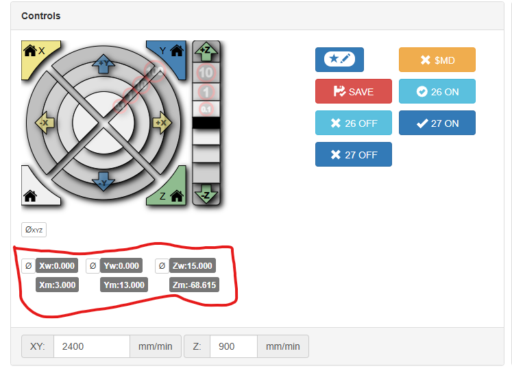
But I’m only seeing what looks like 0.09 difference after probing even though I’m fairly sure (from other manual measurements) that my XMax is about 1mm lower than my XMin.
And if I had got that far I’m confused by “Adjust the Z pulloff in the settings tab.” I assume I adjust one of the two Z pulloffs depending on which motor is higher. But I’m not quite sure which is XMax and which is XMin - I can figure it out with some wire tracing…but…overall these instructions are just still very vague. I had hoped once I was actually working with the machine they’d make more sense but instead I’m looking to do some more research/digging.
That said…I did go ahead and try making something for my girlfriend to help compensate for the time I’m spending…it may have been premature to go throwing it at wood…and I definitely wouldn’t suggest trying this to a 1st timer. But I felt I knew the risks and was ready to do this (despite just having nicked a screw head trying to mark my extents in my old spoil board.)
So as I just hinted I screwed down my old spoil board (which was originally the base for my first build 9 years ago) screwed down a scrap of 1/4" ply I had on hand…then spent an hour trying to remember the best way to convert a STL to a DXF in Fusion only to wind up using tinkercad which “just worked”. And…
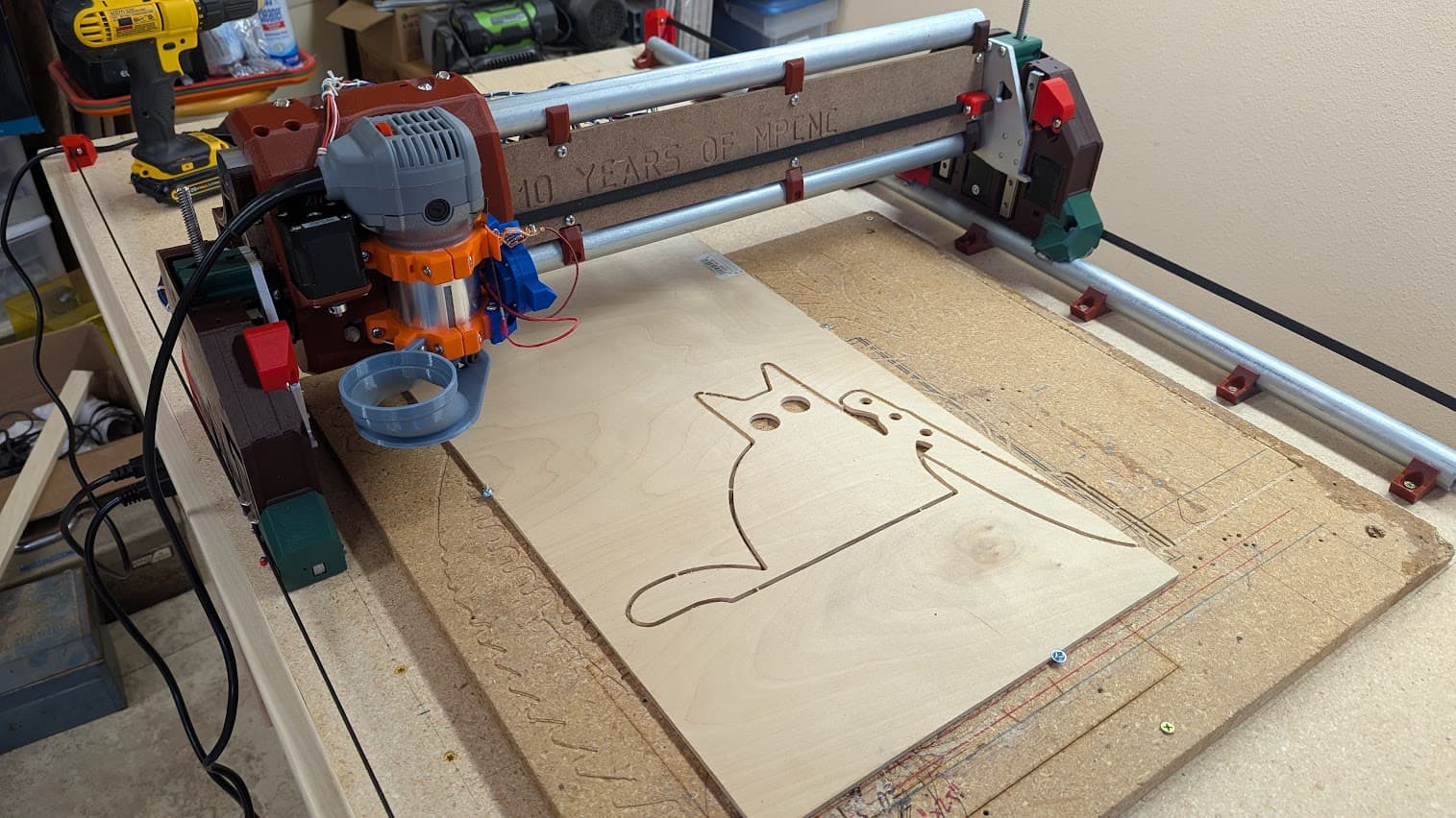
I should have measured that piece of scrap instead of just eyeballing it. Oh well, just looks like murder kitty has a bit of a clipped grind on his knife ![]()
But it worked…it worked wonderously. Way better and easier than I ever experienced with my old machine.
Still need to cleanup the wiring…and figure out how to deal with the power cord on this router…and my vac hose came and I think I just heard USPS drop off those magnets…
But overall I’m really happy - now to do some more reading / research to figure out this Z square adjustment.