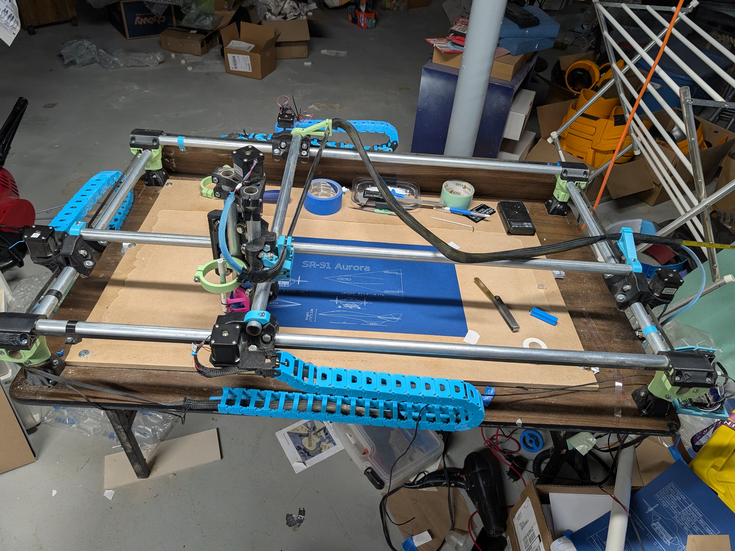
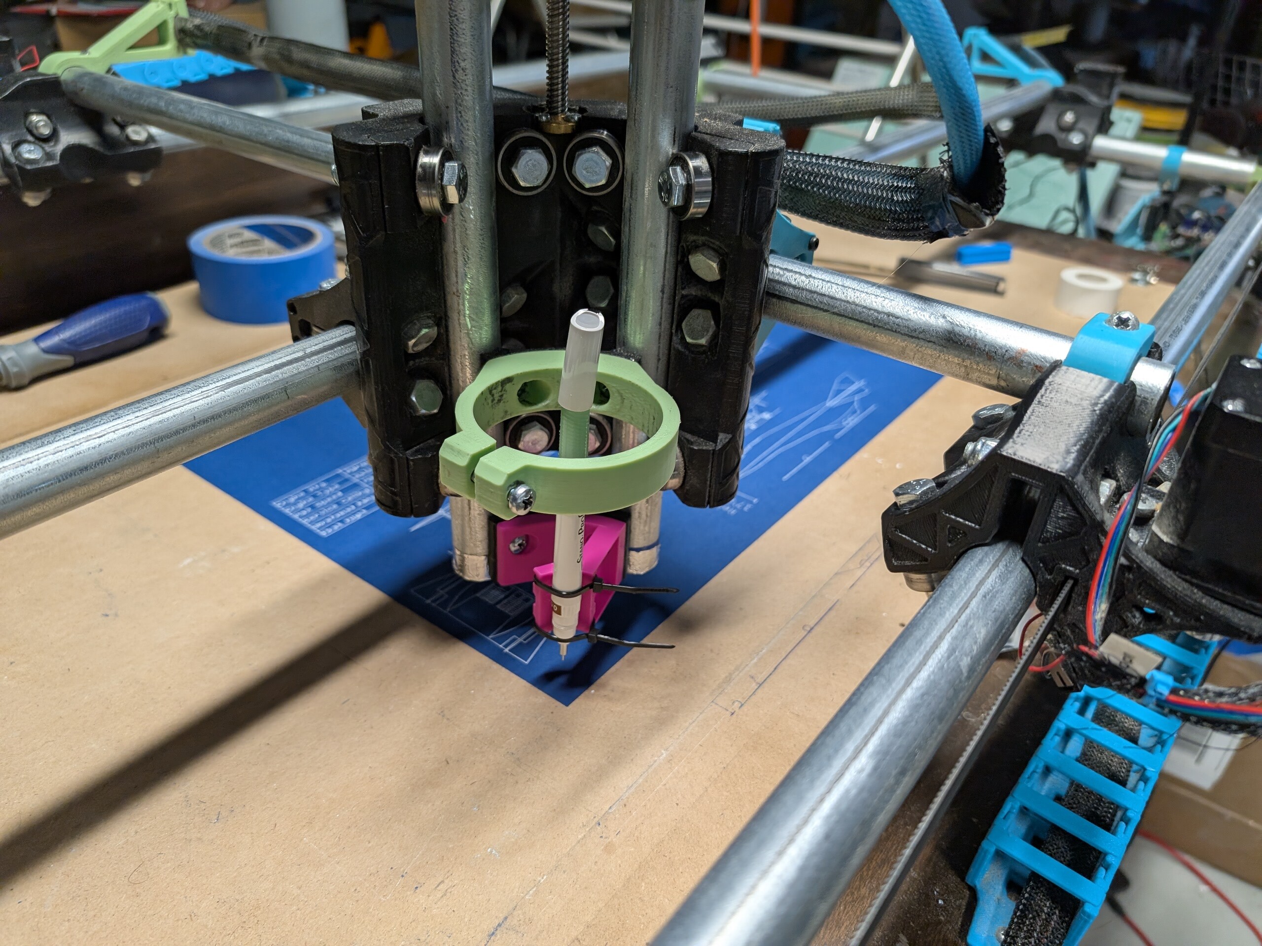
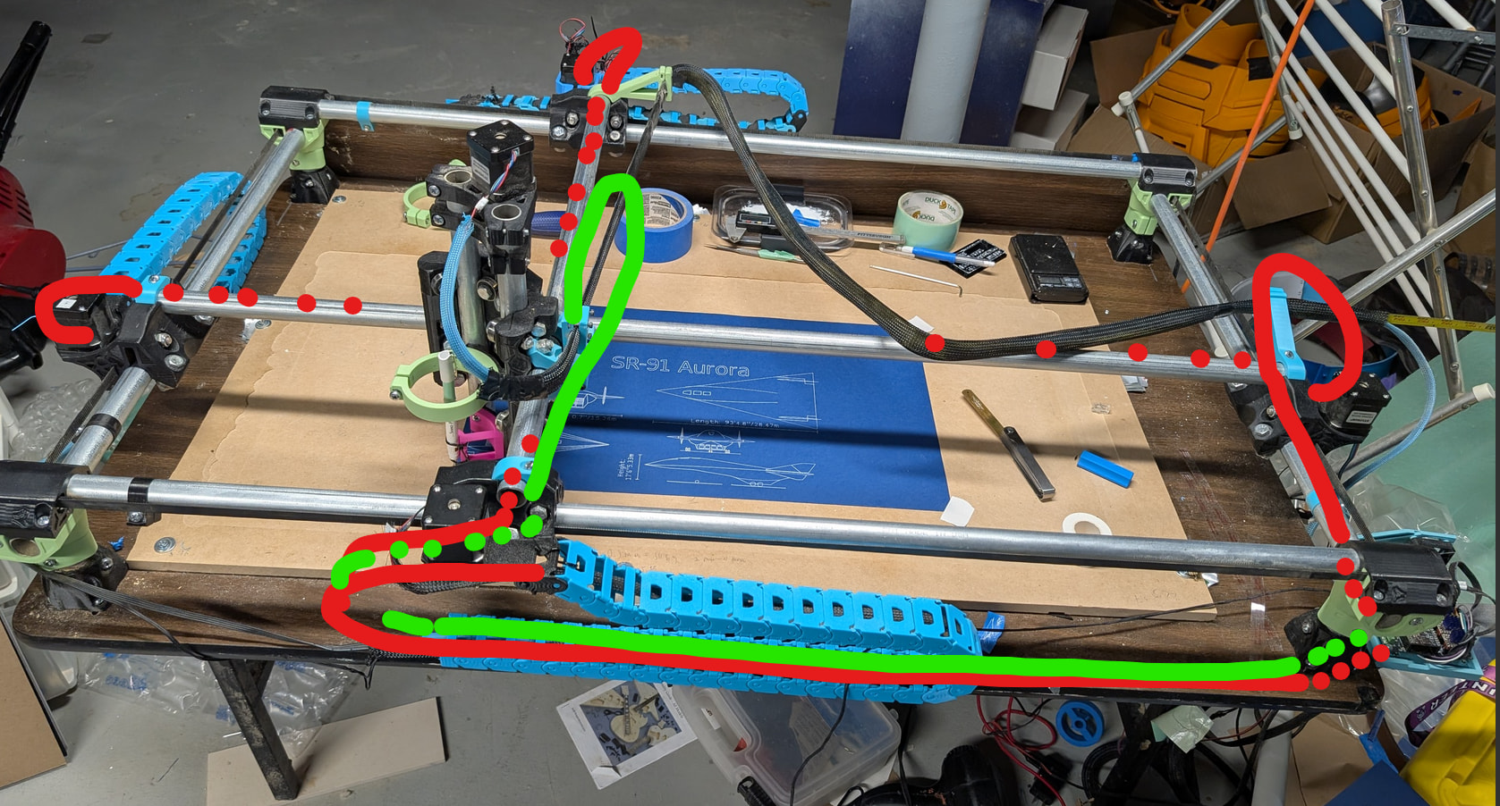
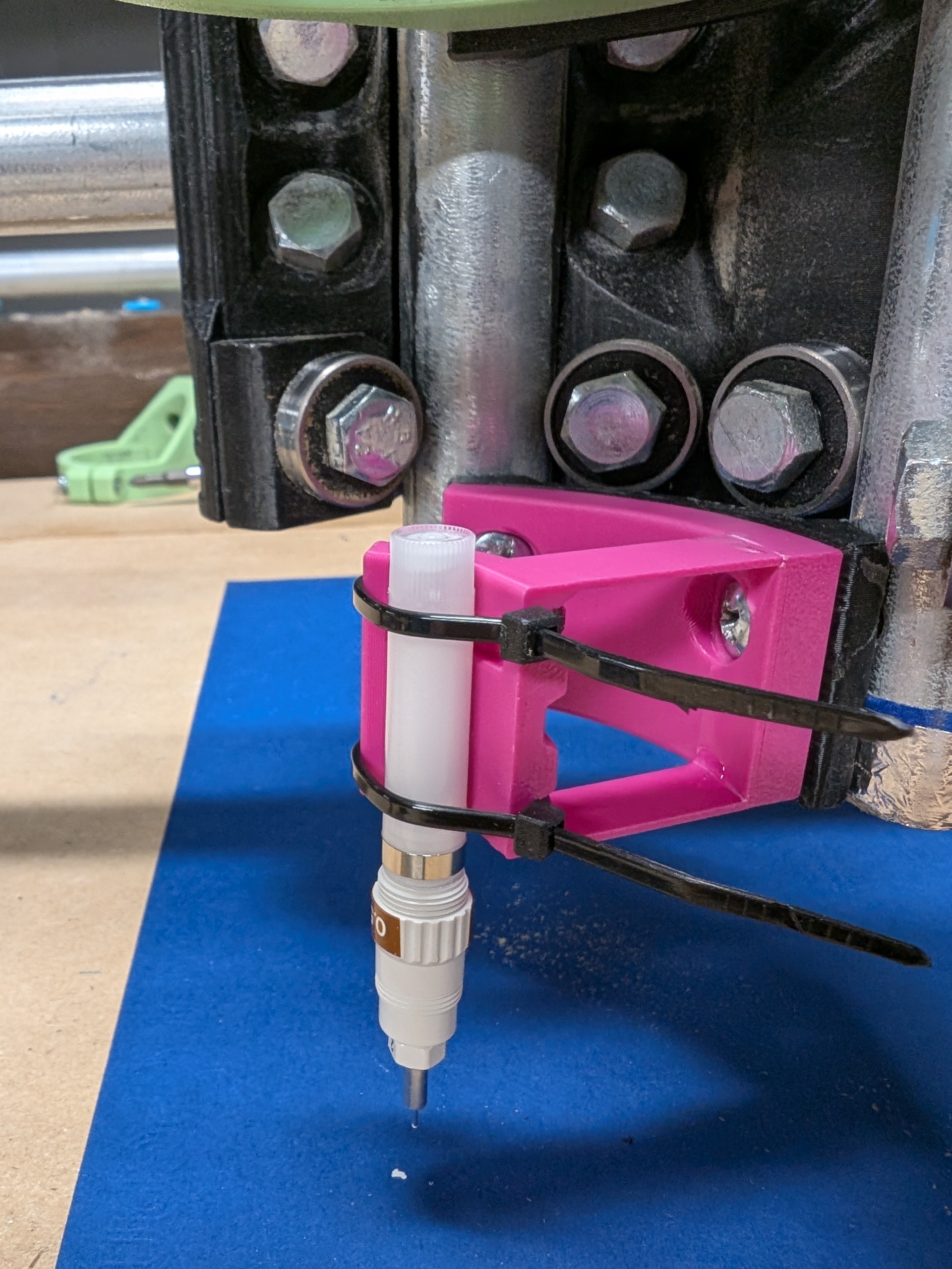
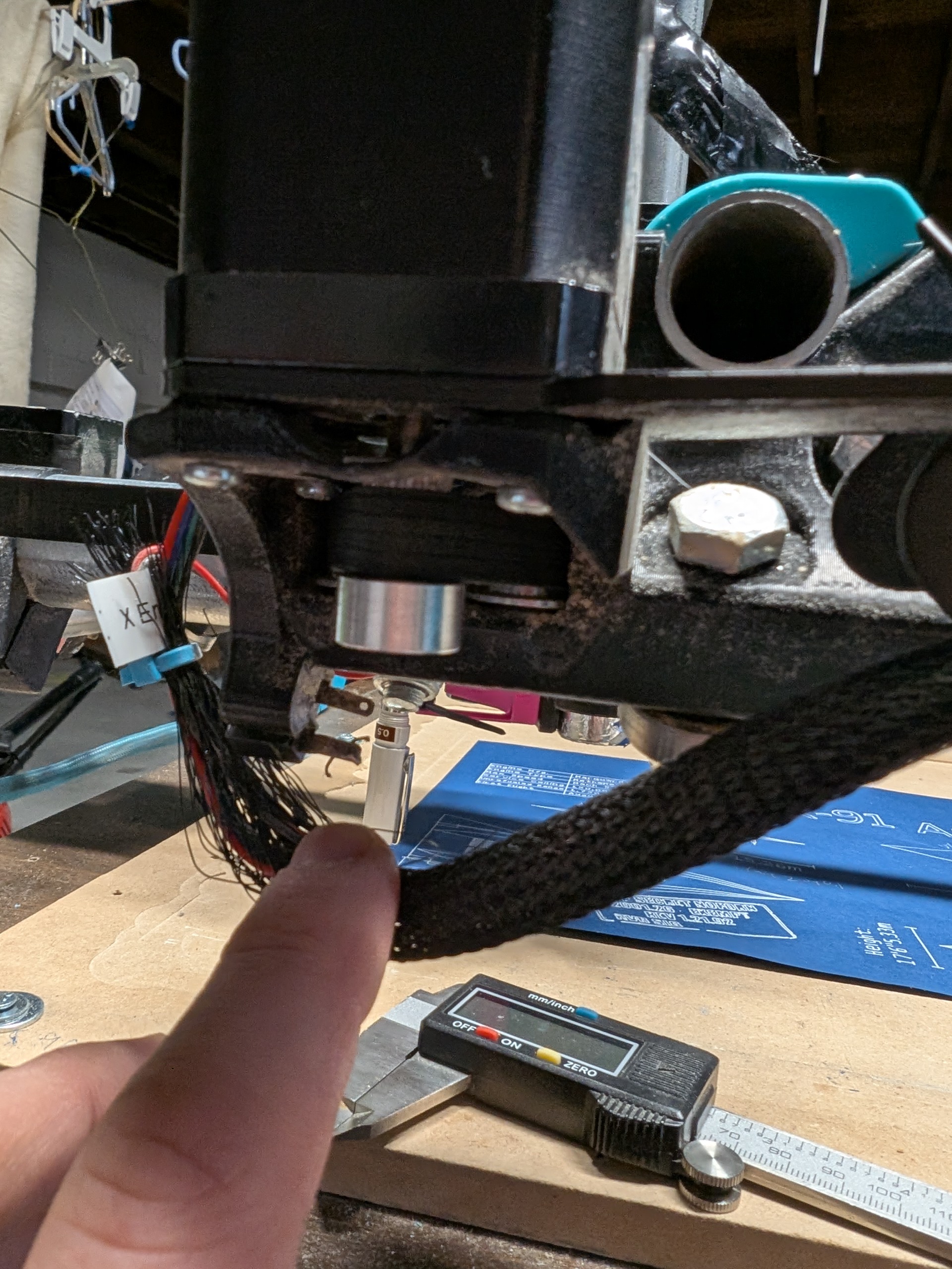
Yeah the pen as is, and an overall view of the machine.
Looking for anything crazy and the pen as high as possible in the mount.
Yeah the pen as is, and an overall view of the machine.
Looking for anything crazy and the pen as high as possible in the mount.
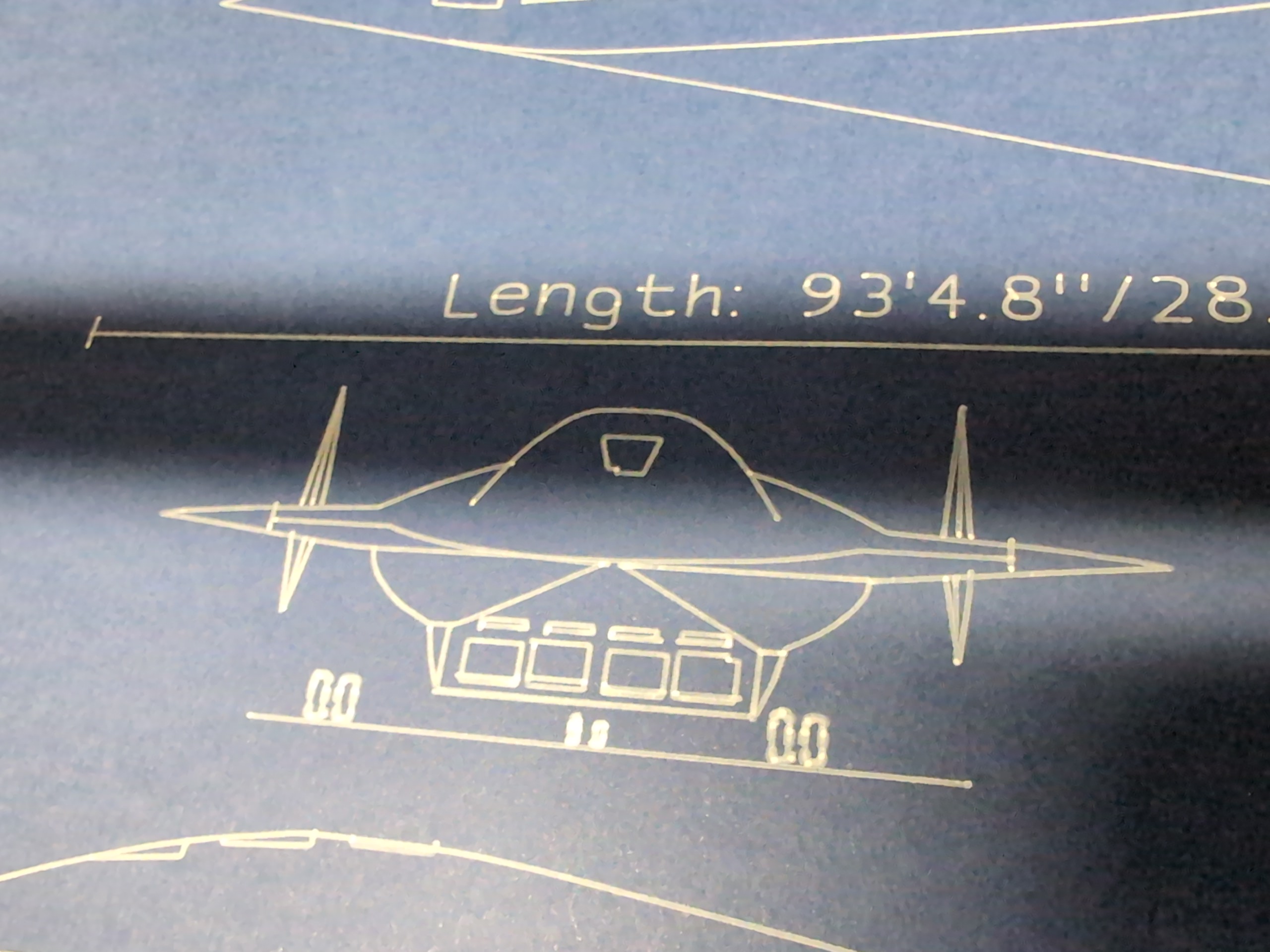
Here’s what I have. I ran out of ink in the Pentel pen so this one was done with the 0.5mm Stano technical pen.
I am sure what you have works but normally we simplify it.
The rest looks pretty good. My next suggestion for the pen lines is to try to wiggle the lowest end of the Z assembly tubes. Is there any free play in there, slop?
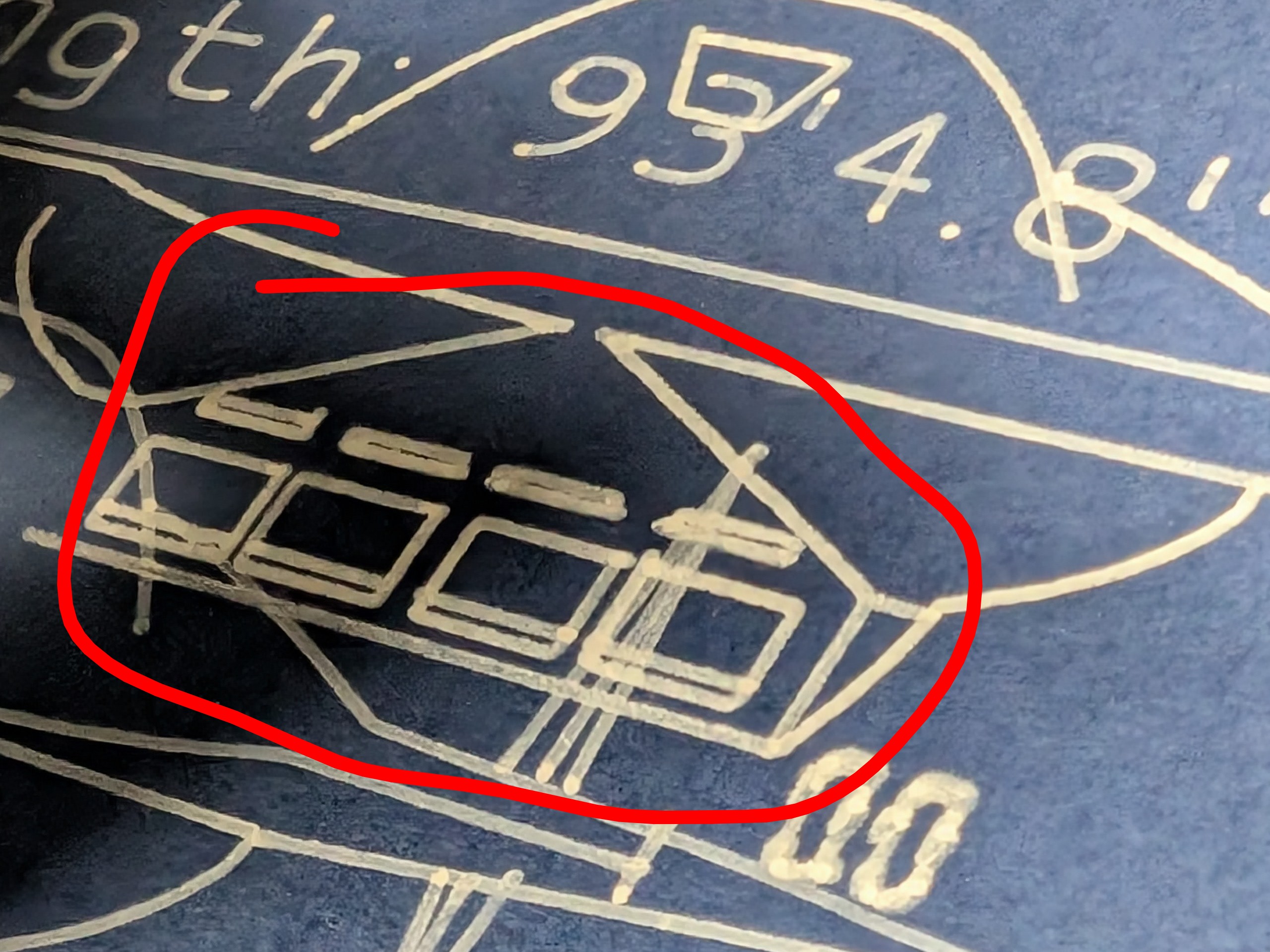
For giggles, I redid the tool settings in Estlcam for the 0.5mm pen and set Fxy and Fz speeds to 2mm/sec. The issues still seem to persist to some degree - it’s still going so these are zoomed in and dodging the gantry.
At this point my money is on loose Z-axis or core.
The pen has almost zero force so there should be no deflection. The pen should have no slop, the pen mount should only move in Z provided the pressure is light. Skipped steps would be huge and would not correct later.
Wait a minute.
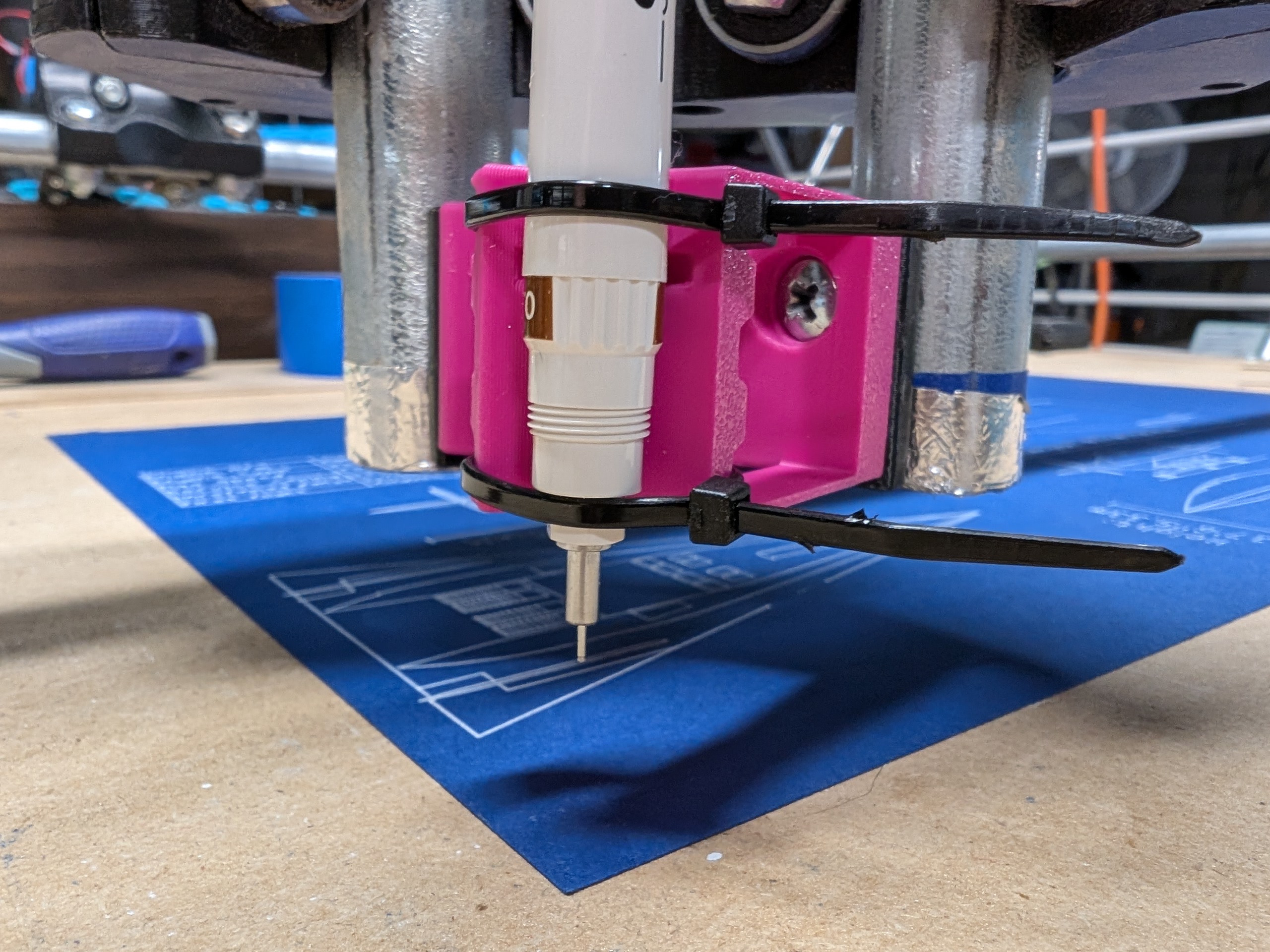
Is this pen mounted at an angle? Slide the pen down further so both zip ties are on the same diameter cylinder. This will hold the pen much better.
The barrel of the pen tapers from thin at the back to thicker at the tip, so the photos you saw were with the lower zip tie keeping it at 90 degrees. I took the barrel off to test with just the ink cartridge + nib, which itself is at an angle - any tighter on the zip ties and I’d crush the tank:
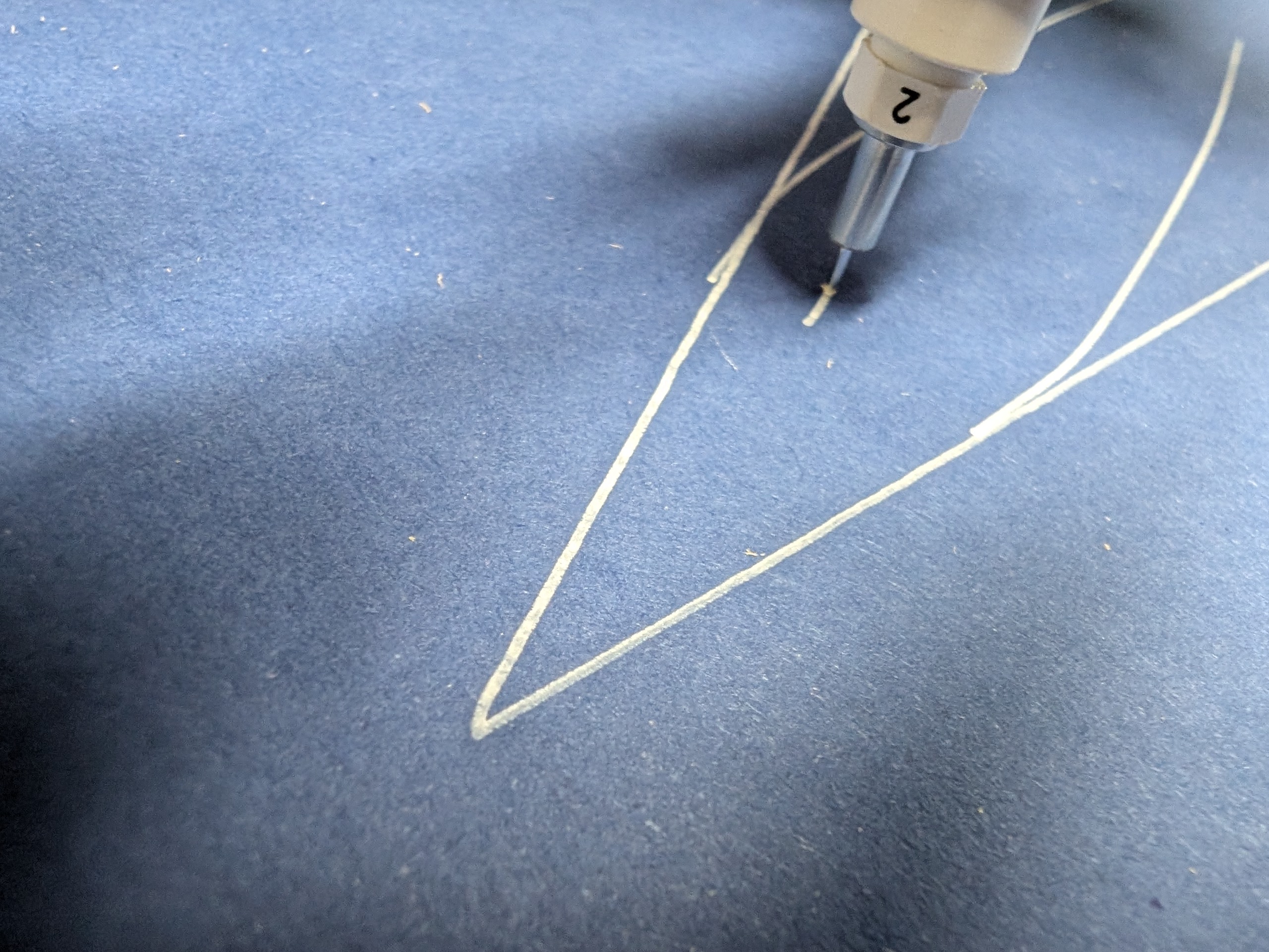
I used the same gcode with 2mm speeds and it seems like it’s already doing the same thing, additionally the point of the triangle looks like it got canted off, it sorta looks like a beak rather than the apex of an isosceles triangle:
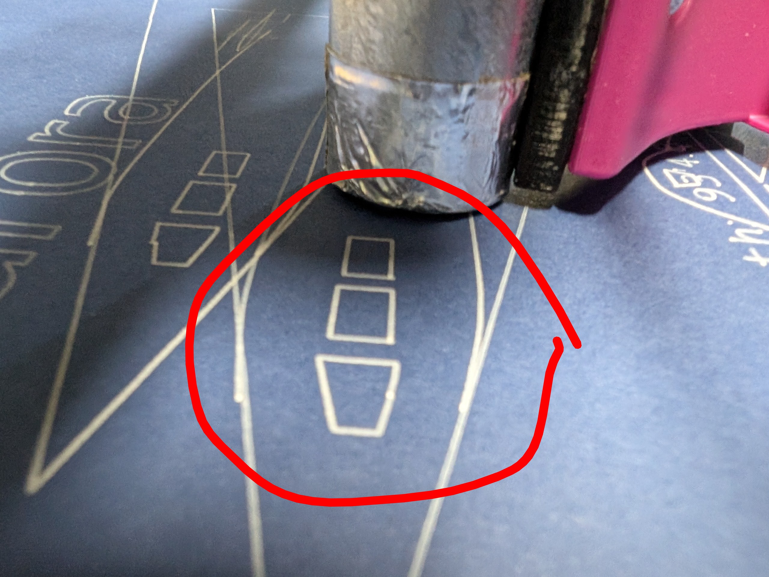
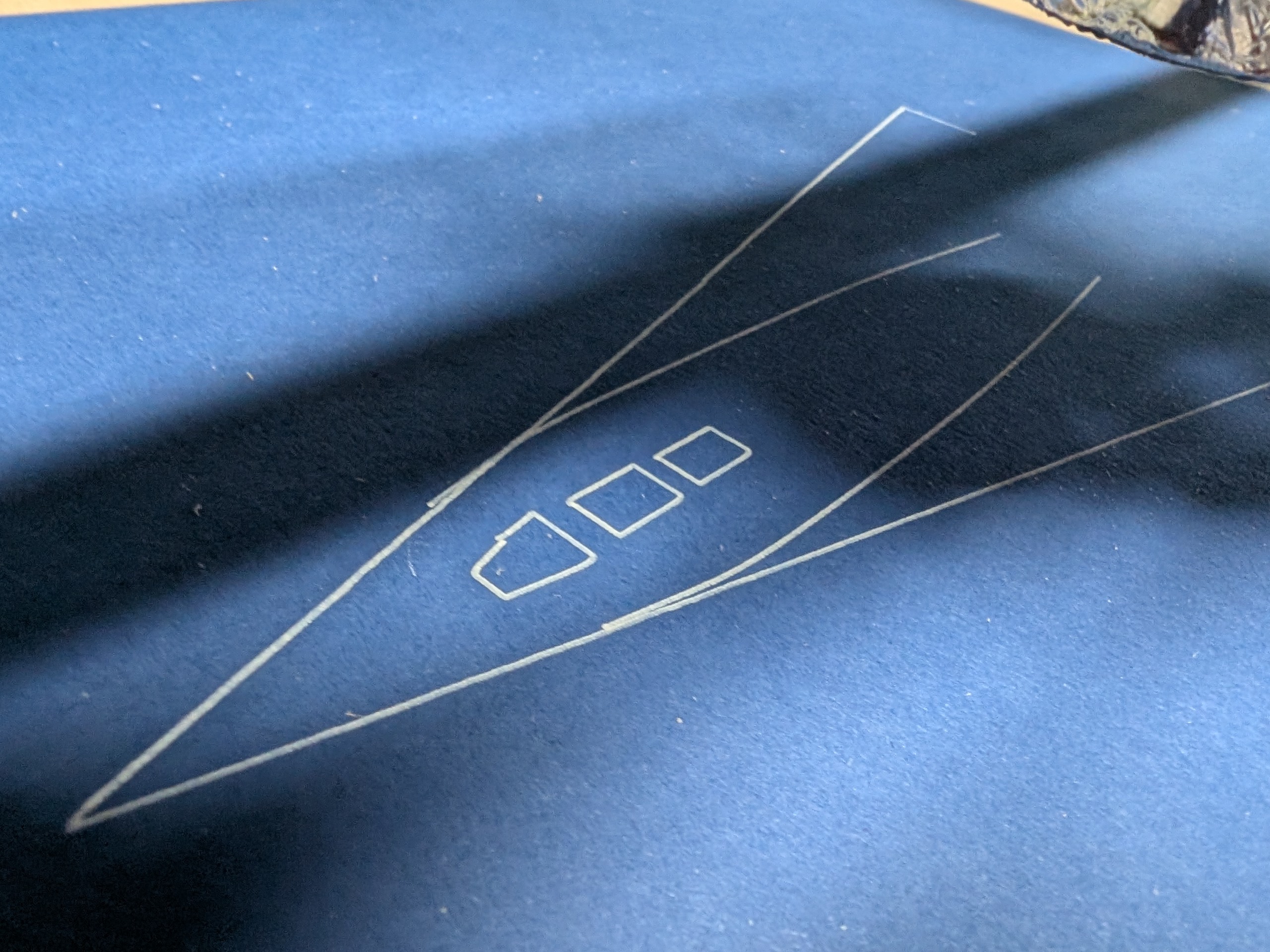
The rectangles and trapezoids are doing the same thing as before:
There’s some wiggle of the entire core when I try to move the entire core, mostly towards the back right. The Z rails feel like they have no wiggle at all within the core. Video of the movement: https://imgur.com/a/ZrjBQ86
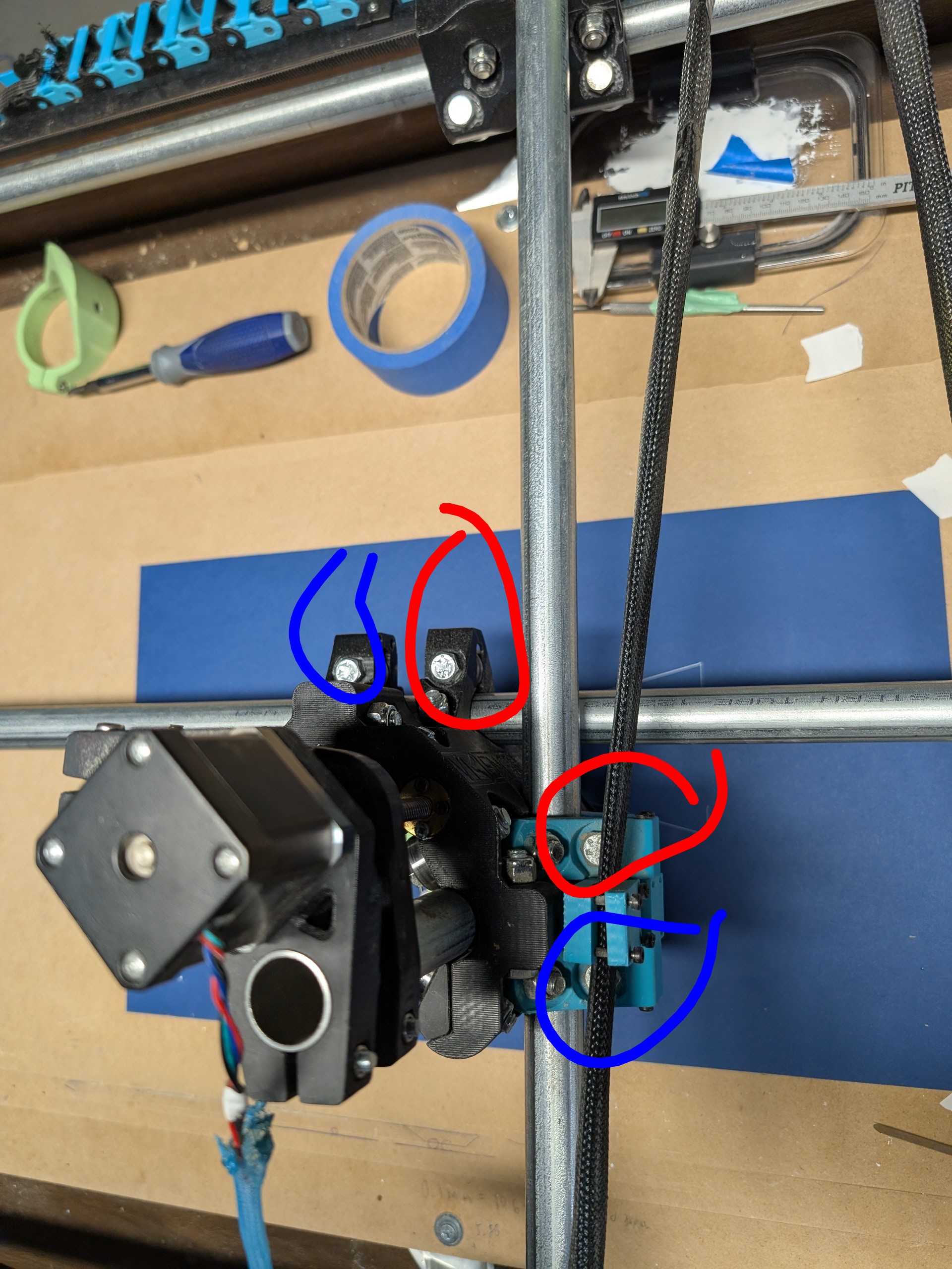
The core clamp bearings circled in blue have no spin when turned with my fingers, the ones in red feel like they have just a little friction on the rail but are pretty close to free spinning.
That shouldn’t happen. The bearings should be able to be turned with a finger, but just like that and not easily.
Definitely too loose.
The drawing is super far off. Far enough you should be able to see something not acting right.
Make sure all 4 of your steppers are powered up.
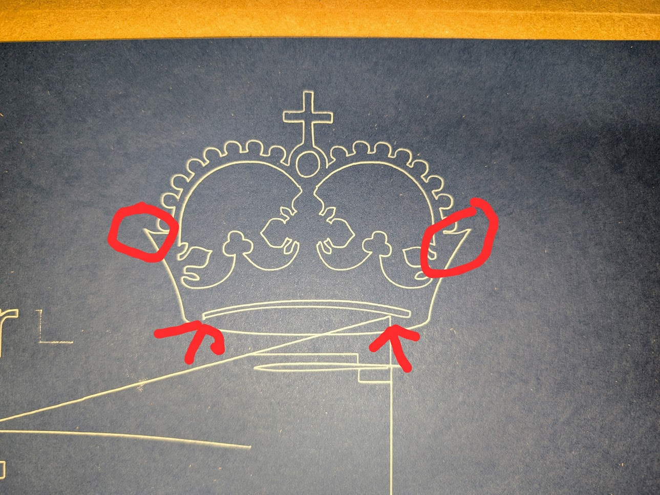
Try the test crown, just in case.
The steppers seem to be powered up. All of them feel warm when in use. The test crown comes out, but it looks like the right side and left side have some difference between them:
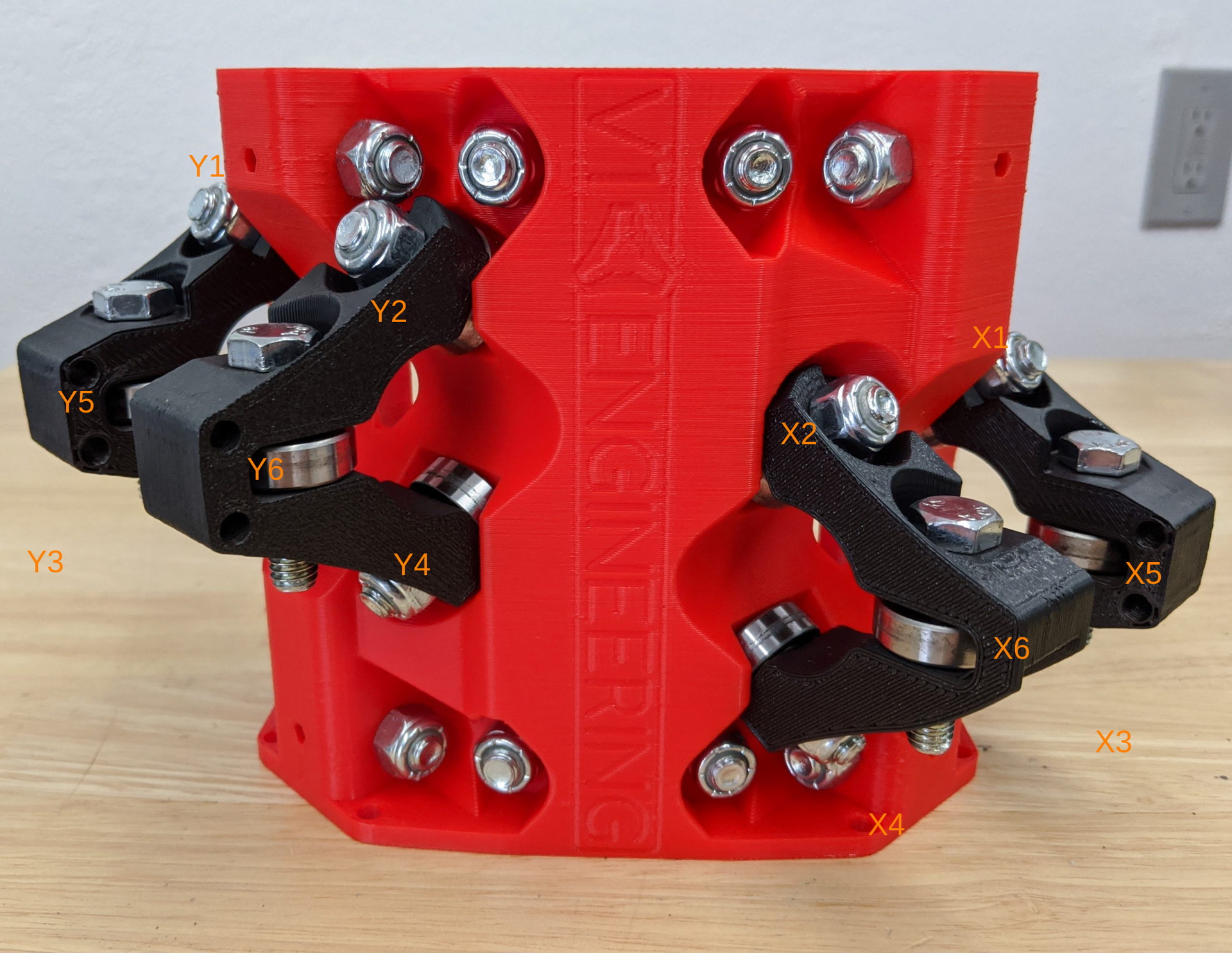
Regarding the core slop - which bolts should I be working on here? I spent the equivalent of days squaring these up more than once so I’d really like to get a rough “do this, then that” idea of how to address this. X5 and Y5 are the ones that are currently tight against the rail, X6 and Y6 are the ones barely in contact:
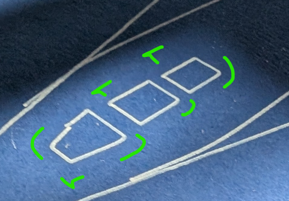
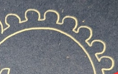
I don’t know how to fix the slop but you’ve definitely got some. These are supposed to be circles (cut off at the bottom where they attach).
xy 5&6 provide the tension.
If you run out there is a way to get more.
Unfortunately dual endstops make this trivial, if you don’t have them I would settle for no slop over a perfect rectangle.
You can also use the spacer block method to start extremely square without endstops as well.
Sorry, I meant squaring as in the part of the build where moving the gantry gave equal results - on the road at this point so I can’t quite recall. I’m using a Primo, so unless I missed something, it has dual endstops. Jackpot X/Y homing is the same thing you’re talking about, right?
As to testing against the crown, is it just a matter of loosening X5/Y5 1/16th a turn at a time and running a crown test, then measuring circle sizing to match the Estlcam version?
Whichever one has a super loose bearing give it a little 1/16 turn until it snugs up a bit. Jiggle the core to make sure the slop is gone. Keep going on each loose bearing until it is gone.
If you are using dual endstops this should not affect your squaring.
OK, I have the core wobble defeated. I’m still seeing some of the odd deviations - could this be an issue of improper belt tension? My current MO has been to plot the crown and measure the OD of the central gem and one of the circles on the plotted image against the one in Estlcam, then tightening all belts on an axis that was too short or loosening if too long. My concern with that is that if only one of x1/x2/x3/x4 or y1/y2/y3/y4 tensioner is the problem, this doesn’t narrow it down.
iIs there a calibration test image I should use? Maybe just four squares, one in each corner of the plotable size of my MPCNC?
That is not a true circle.
It should not be the belts, unless they are super loose.
Well, I am not sure how we got this far before someone thought to say it… Better check the pulleys.Make sure they are all tight.
If they are tight, lets see a good video of it in action so we can see where the issue is coming from.
Sorry - “Check the grub screws” is one of my mantras, but I’ve been away a few days helping my mom pack up for a move to a new apartment.
Do you mean if the pulleys are tight on the shafts?
If so, it seems they are tight - they have no vertical or lateral movement on the shafts, but I can detension the belts to check for sure.
I took a quick check and at least one pulley looks a little high compared to the idlers - should I lower it (and any other that are high/low respectively)?
Just make sure all the grub screws are tight.
Something is loose somewhere.
All the grub screws are super tight and the pulleys aren’t moving.
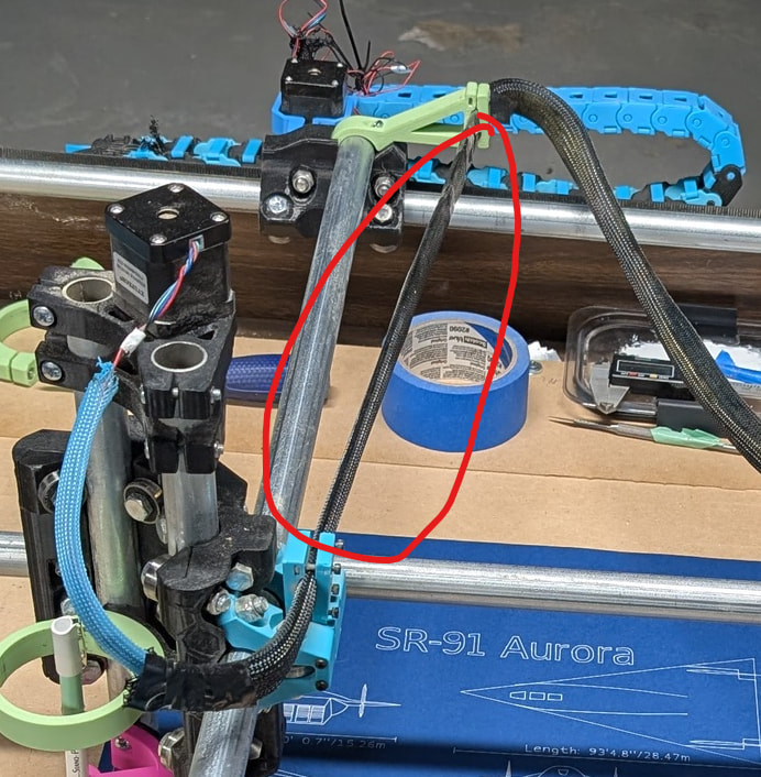
I did find some looseness in the rear X gantry and left rear corner - the corner part seems like I just need to put some vinyl tape on the vertical pipe to torque the corner part into place. The gantry I’m guessing will need bolts tightened, should I be tightening the ones in the bottom or on top of the rail?
https://imgur.com/a/OpAgLTn for video of the wiggly parts