I’ve got a gel pen in my MPCNC and am using it as a plotter. I’ve put together an SVG of blueprints to plot out, but I keep on having odd errors when it starts a shape.
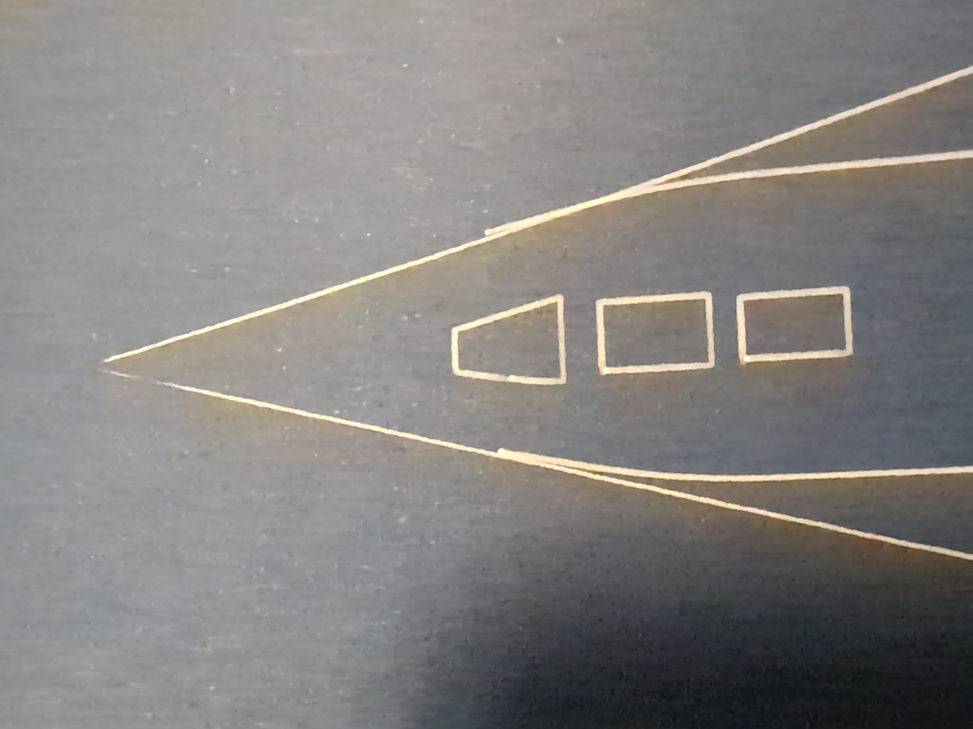
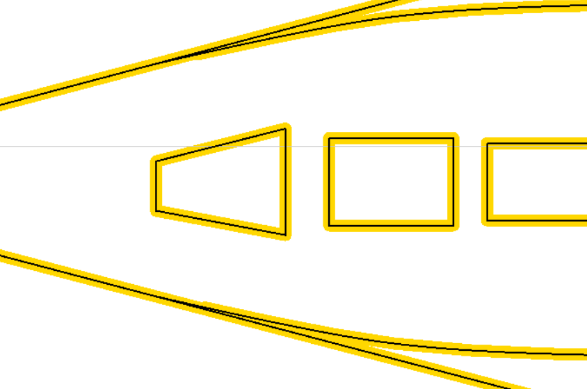
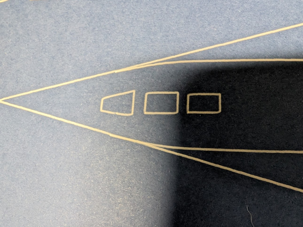
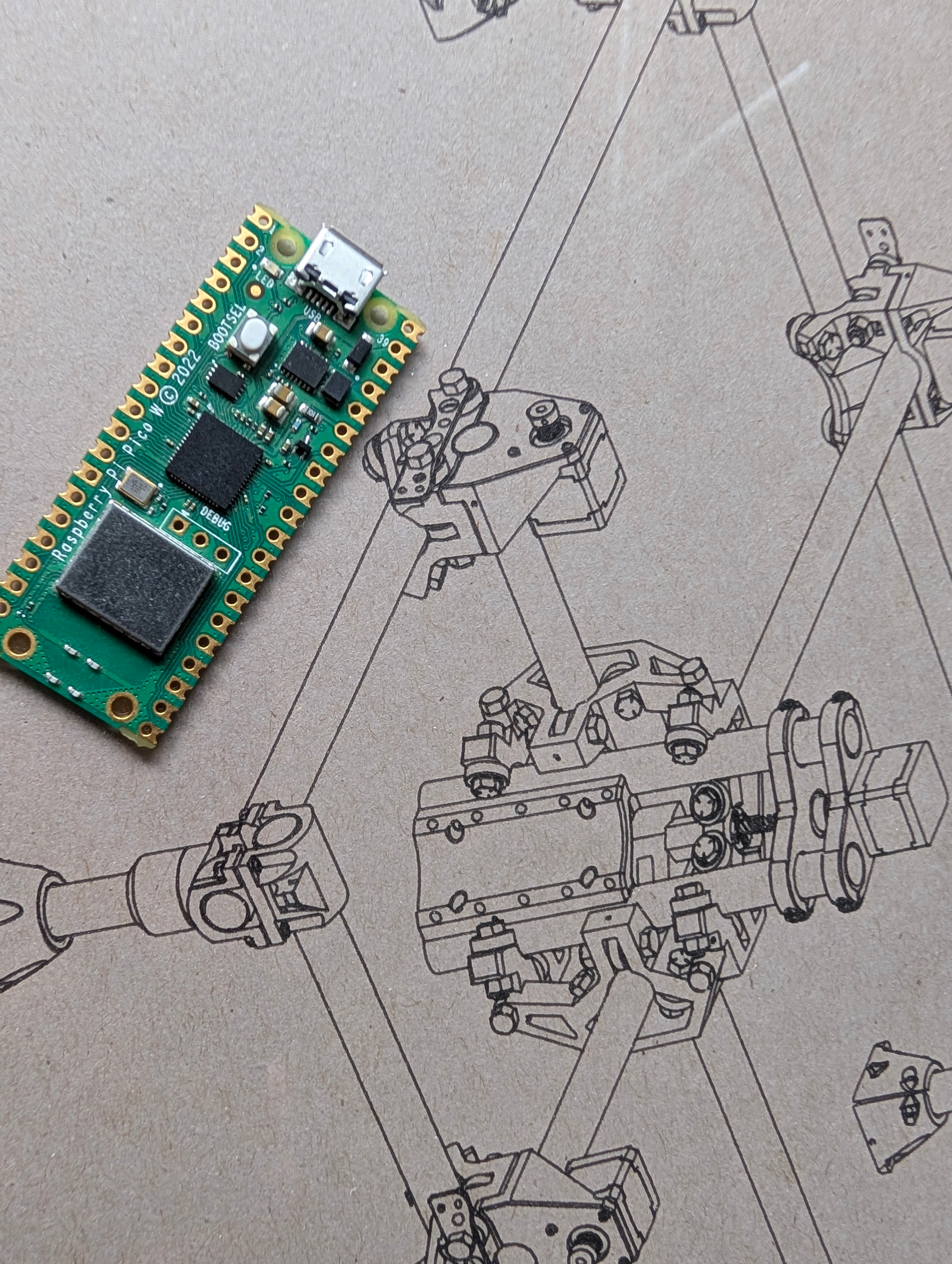
The curved bulges align well enough with the straight edges, but they’re offset by a mm or so. The bottom half of the trapezoid on the left has an offset for some reason, and the bottom left corners of the rectangles are offset as well.
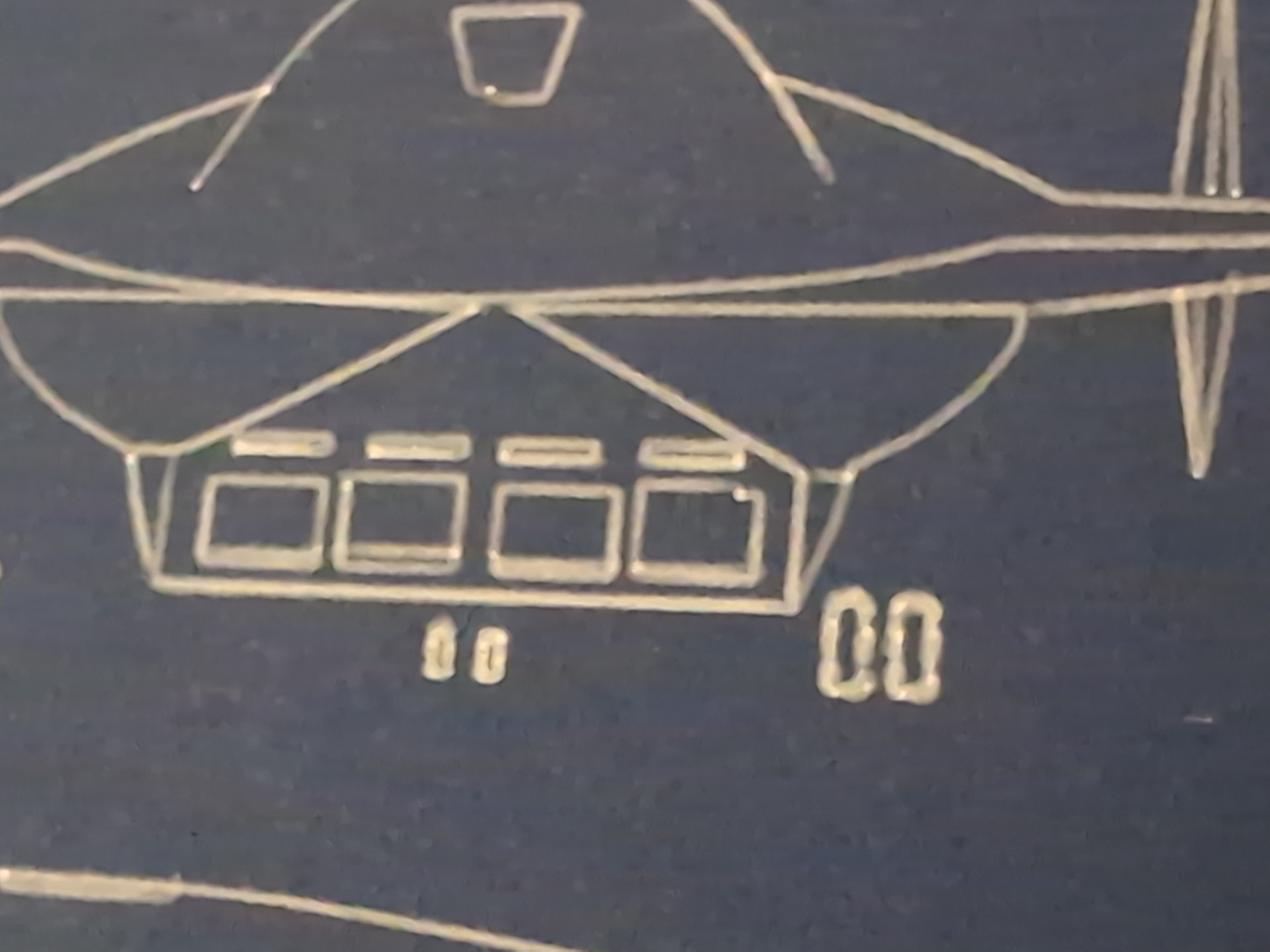
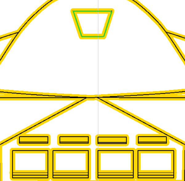
The bottom of the trapezoid here is offset as well, the corner of the rectangle on the bottom right is offset but none of the others are offset, and only one of the rectangles has the 2nd line drawn on it.
The pen is on a spring mounted holder so it always has enough pressure to keep ink flowing. I’ve tried the plunge angle at 90 degrees, 1 degree, 15 degrees, and 89 degrees - it seems to replicate the same issues every time. I checked my belt tension and made SVGs of 20/50/100mm square patterns to test calibration - they all come out fine.
I had nothing but success with another SVG I made - the lines all draw as they should. It’s a completely different SVG so it’s not exactly apples to apples, but I honestly don’t know how to fix the blueprints.
On the Inkscape front, I’ve gone over all the original paths and they are all either closed shapes with cusp nodes snapping to cusp nodes or cusp nodes snapping to paths. In Estlcam I’ve tried manually creating shapes with Engrave → Manual Shape Detection or by using Start Point to ensure everything starts on a corner, but I keep getting these errors in the same spots, draft after draft.
Could anyone please advise what I should be doing here, either in Inkscape or Estlcam, to fix?
Use the Preview tool to view the G-code paths. If the pen drawn paths don’t match the G-code paths it’s a mechanical issue. Either the pen is moving/flexing and/or steps are being lost. With no knowledge of the machining order it’s hard to know, but the equally offset lines in the first image looks like step loss…
Estlcam likes starting in the corners where direction change/acceleration might be causing those corner jogs. You could try setting start points in the middle of straight sections using Manual shape detection.
Have a look at my pen holder, then use the lightest pressure possible. We typically use 0.5mm for a plunge, or less.
If you are using a mechanical spring or rubber band style mount they have way too much play. Mine is a flexture and only deflects XY under far too much pressure. We use it at the *RRF with a 0.3mm pen and the lines are flawless.
I’ve been using one I designed that uses a cone-shaped hole holder in the bottom ring of the router holder with a sort of collar that holds on to a pen with screws, and uses springs to maintain constant downward pressure. It holds a constant downward pressure, and I wrapped painter’s tape around the pen to ensure it has zero left/right play.
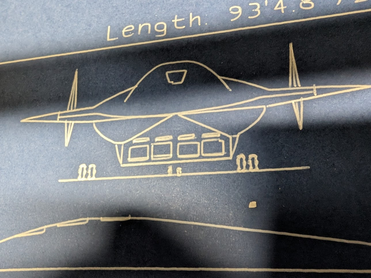
Tried with yours + no changes to the gcode. It’s set to plunge 0.5mm, Fxy and Fz speed are both 5mm/sec, and unfortunately the issues recur but in different amounts of offset, plus the corners somehow get a bit beveled:
The pen mount also doesn’t flex enough to account for surface height variations - other parts of the plotted results were dug so far in that it almost tore through the paper, others were on higher parts so that the pen was too low during moves. I can account for those in the start height for the engraving steps in question but it seems like lateral pen movement isn’t the only culprit here.
Should I be looking into a step loss issue and if so what’s the general process for that? Is it redoing gantry squaring or something different?
let’s see a picture of how you have this set up. The pen is usually some of the most accurate things you can do…provided a light touch. We draw lots of pictures at trade shows and we are drawing the threads on tiny M3 screws in ISO drawings with that 0.3mm pen.
The surface does need to be flat though. Overall deviation has to be under 2mm.
I’ve already surfaced and done some shimming to correct the variation. Last time I checked, I think it’s around .8mm higher on the right than the left, but I can retry and re-tram if needed.
As to pens, I’ve tried a whole bunch of different pens for this and it seems to reproduce on all of them. Just to narrow the range, let’s put it as down as occurring on a Pentel Hybrid Gel Grip (0.8mm tip), Zebra Sarasa (0.5mm), and Stanograph technical pens with thinned Ph. Martin ink (0.35 and 0.5mm tip sizes).
I’m using what I believe is a light touch - 0.5mm plunge depth, using a feeler gauge height at anywhere from 0.2mm to 0.4mm to ensure it doesn’t plunge anywhere more than what it needs to just leave a stroke. The spring loaded mount I put together at least keeps the pressure to absolute minimum.
Machining order is all automatic but I think I saw someone mention getting these done first - will try that with the Pentel and take the speed down to 1mm/sec to REALLY rule out going too fast.
What pen do you use for this? I’m happy to buy one that’s known to be correct for this, I just went into it from my own research and permutation. As long as it comes in white ink or it can be loaded with white ink.