Now that we understand this a bit more. I can go ask Bart if he has a strong opinion one way or the other.
On the bench, I would install a resistance substitution box an run it through a range of values. You could just try swapping up a few values and see what the serial looks like on the scope, and also verify motion still works.
Could it slow down overall communication speed or anything?
No, what would happen is at some threshold UART comm would stop working. You’re building a complex divider with the pullup resistor on the dev board (weak pullup), the leaky TMCs pulling you down through a 1K (strong pull down). Putting a 1K pullup in parallel with the weak dev board pullup now means you need the serial line drivers on the ESP and TMCs to have enough drive to overcome the pull up. It looks like they do.
Another test might be to see at what value your added pull up becomes effective. We’re now looking to find the mix of values that will always boot and which never miss comms to the TMCs.
Okay, I think I better try that in the morning. That is going to take a steady hand and maybe a microscope.
Thank you for staying calm!!
I will try my hand at soldering a through hole resistor on that very tiny pad. once I get some leads on there I can swap it out easy enough.
Thanks again. I will let you know as soon as I attempt it.
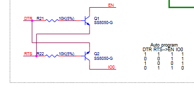
This also makes the terminal connected scenario more clear. When fluidterm is connected and driving the USB to serial chip, the hardware handshaking lines come into play. Fluidterm thus adds a strong pullup via the handshaking lines. That is able to overcome the pulldown of R8 through the disabled TMCs. Its a similar effect to your 1K strong pullup.
Why Fluidterm matters now seems obvious.
So if the ST_UART line goes into the first three drivers and when they are populated, that is 3-20k pulldowns. Does that help in balancing the R8 resistor?
3x20k resistors in parallel =6k
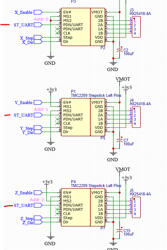
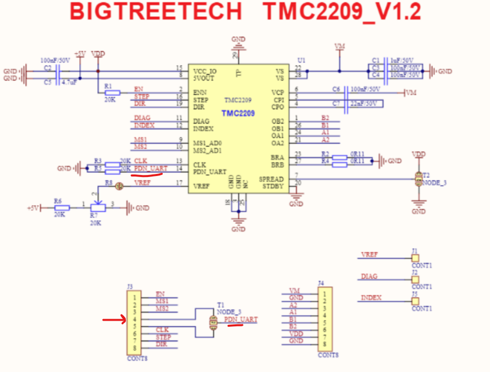
I think this is the ESP32 gpio0 (https://dl.espressif.com/dl/schematics/esp32_devkitc_v4-sch.pdf)
Where is my Brownie badge for hand soldering to a 0402 resistor pad…
edit
edit
So I tested a lot of things.
I think the 1k pullup is the best solution so far. At least to the extent of my understanding.
If I change out the R8, 10k no change, 14.66k and above the esp32 fully boots but there is no UART communication.
The 1k pullup makes the UART coms stop working at 5.86k and above. (actually at 5.86k only y2 and z2 work XYZ no go). Above that none work.
So maybe now I need to check the pull ups and the highest that works reliably?
So for the pullup, 7.5k works, 8.5k does not. (for the genuine).
So maybe 5k is a better option than 1k?
1K is a pretty strong pullup. I need to think about that a bit more, but the other test is to see if using the USB connected fluidterm ever stops being able to load firmware at the various resistor values. I think you’d be fine at 4.7K pullup, but would want you to verify that by test.
When using fluidterm and all of the X/Y/Z TMC2209s installed are you 100% reliable flashing with a 1K pullup? How about a 4.7K?
OK, so if I parsed that right… If you just vary R8 without any additional pullup, then you have to get it above 14.66K to have the ESP32 boot- but then you have no serial comm. On the scope shots I bet you see that it’s no longer possible to pull the serial level down far enough. Comm probably fails well below that point.
Then with the super strong 1K pullup in place, UART com gets flaky above 5.86K for R8.
The design objective is to:
- be certain Jackpot always boots reliably (5K ohm or less added pullup)
- Find a value for R8 (which is a current limiting kludge for the TMC leakage) that is high enough to not fight with the pullup resistor but low enough to ensure UART comm works after boot.
- Ensure fluidterm can always flash whatever ESP32 dev board is installed (Not too high a pullup ristance nor too low an R8 reistance).
1K seems agressive (too low a reistance) to me for the pullup. My gut tells me something like 4.7K is a bitter choice, but I’d want to see that tested.
1K for R8 Seems also too low a resistnce as well. Again, gut only, something along the lines of 2.2K or 2.7K feels like a better choice.
What happens if you test Fluidterm flashing behavior with a 4.7K pullup and a 2.2K R8? Does it always flash reliably? Does the Jackpot always boot when powered without the USB cable installed to a host?
If all those states work with those values, then they seem like a good set of values.
Edit to add: Did Bart ever elaborate on why 1K R8, and what else he doesn’t like that implementation?
Gotcha, I can do that.
Correct.
Bingo as well.
Agreed, seems a bit…open.
K, I can check.
Sounds like a solid plan!
No, I got a reply but no substance to it.
Thanks, having more eyes on that is great. I am understanding the system a bit but not enough to just know what is right. I tried a ton of values to follow the trends. I will test with the new info ASAP…I need to order more boards so I think I am going to risk the next full batch with whatever fix comes out of this.
You can scope pin 4 and pin 0 to see what the voltage across R8 is. The UART signals should be visible in your scope. I don’t think adding these resistors should greatly affect transients (rise times). And the signal traces on the boot pin look like the uart talk is very close to 0-3.3V. But you want to zoom in there and see that talk both ways is good.
I think the reason R8 is so small is in the case when a TMC driver is sending and so is the ESP. I think the ESP is supposed to win out, so having a much smaller resistor means that TMC X can’t keep ESP from talking to TMC Y.
Maybe I haven’t been burned enough by these things. But leaving the pullup and R8 at 1kOhm doesn’t bother me. Half a milliamp isn’t going to break anything. My only concern is that the resistor dividers all come up with reliable signals. But I think I need to draw them all out. What is the voltage when TMC X is transmitting, or X and Y, what if there is no Z. It gets complicated fast.
Why is this a concern? You think the pullup is strong enough to mess with the dtr/rts signals? Those are going through saturated transistors, not resistors. It should ground it very well.
I’m wrong about this. I am pretty sure.
There’s something about those TMCs and their communication bus that is interesting here and we must not be understanding properly. That must relate to why after 3 TMC2209s for X/Y/Z , the 4th through 6th get the mux treatment. I looked over the Jackpot schematic again, and I realized that the lower portion I’m quoting is a screenshot from somewhere and not actually a part of the design.
Jackpot doesn’t have 74HCT4066s nor the 74HC1G125. That’s noted as optional, but it is at least instructive about the UART communications.
The reference embedded in the lower part is not how the Jackpot is connected. My gut says that after 3 UARTs bussed together either UART comm or ESP32 boot behavior became unreliable and thus the addition of that mux. We’ve rediscovered the boot reliability issue.
The muxing seems like an attempt not to need another GPIO expansion to be able to talk to each TMC one at a time. It seems pretty messy.

It’s not just whether the pullup resistor or the drivers on the serial port of the USB chip are strong enough to yank the signal levels around. Also not a concern for stressing anything with the relatively small current at work here.
I don’t know what capacitance is present nor input impedance is for the GPIOs when running , so I’m worried about the timing of the rise and fall when doing the “reboot now come up in bootloader” dance.
That timing may be really slow and super robust, but I want to be sure the changes don’t break that dance. If it was a problem I suppose the answer to that could be as simple as just instructing users to pull the ESP32 off the jackpot to flash it- but that seems like a hack that shouldn’t ever need to be done just to get the system to flash. Most folks would only need the web flasher anyways.
You could be right that it just doesn’t matter- but I’d still like to see it tested. Then again, testing things to be sure they can’t fail is what I do- so it may be overkill in this case.
The esp needs to put settings on each one individually. They may have only three configurable addresses. Or they have timing requirements that get too tight for 6 drivers. I definitely haven’t looked into it. The skr boards are another possible design to look at.
AFAIK, Ryan is the only one using the boot pin. So this isn’t the reason there is a mux. I was going to suggest we swap pins around to avoid pin0. But at this point, it is the devil we know. It may be better to use it as a pin we can keep tightly controlled. Moving it to some spindle output would be easier today, but cause issues for users down the road.
That makes sense. I would feel better if we saw the uart bits up close. Before and after R8. I don’t even know what baud rate they are. Smaller resistor could affect rise times on those signals. But if it is 9600 or something, it won’t matter.
That is fair. We should definitely be testing flashing (and things we don’t think are going to be a problem) with the next RC board.
I don’t get warm and fuzzy feelings about trusting the testing for resistor values though. There are obviously a lot of variables in these esp boards. So the tests where it works at 7kOhm and not at 8kOhm make me nervous. I want to stay far away from those limits.