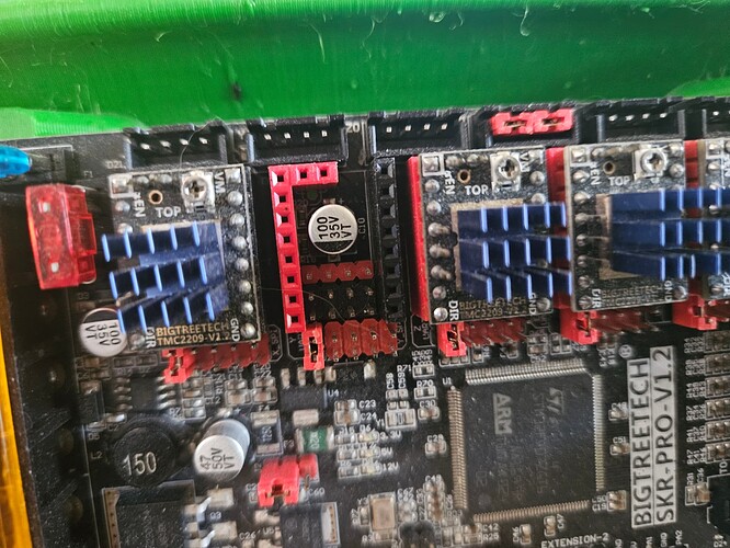
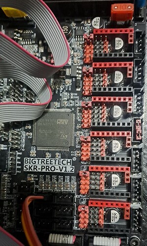
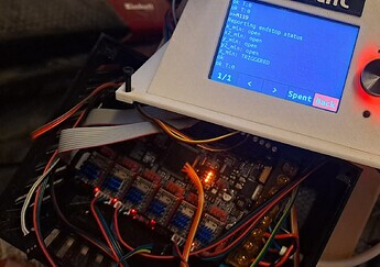
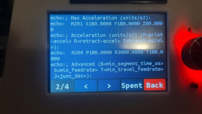
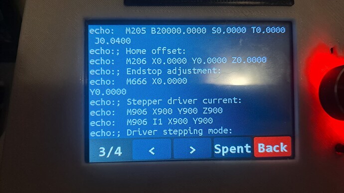
No, under the drivers. Like I say, grasping at straws, but somethjng is weird with your board to get those results
oook! let’s go deeper and deeper ![]()
Thank you, my friend, for being by my side during such a difficult time! ![]()
EDIT:
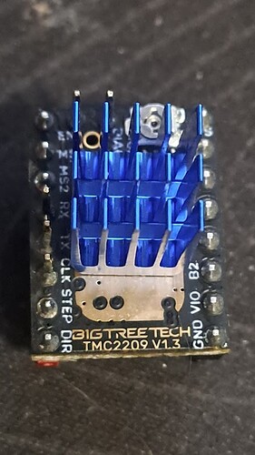
I noticed that my drivers are 1.3 and yours are 1.2
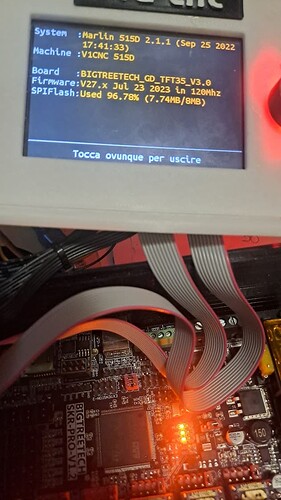
Did you confirm that the firmware actually changed (firmware.bin changes to FIRMWARE.CUR). Also did you use the filename V1CNC_SkrPro_Dual_2209-2.1.1.zip with a date code of Sep 25, 2022?
Sorry to be questioning this, but as @SupraGuy says, something is weird here, so we just want to make sure that we’re not overlooking something obvious.
Also, do all three yellow LEDS on the board light up? (12V, 5V, 3.5V)
Mine was made before the resistor issues were happening. I can’t see that being the issue.
This just bugs me. This should only ever happen if all the endstop signal pins are below the logic low theshhold. That is, connected to ground.
The signal pins should be connected to the +3.3V rail through a resistor. This resistor keeps the circuit from shorting out power when we connect a switch.
At some point the LEDs, also connected to the signal pins, got too low a value resistor, causing the LED to drain too much current, dropping the signal pin voltage below the logic low threshhold. Those SKR Pro hoards either do not read triggered at all, or only intermittently do. This is similar to the condition you seem to have.
All of the SKR Pro boards have a bug where if you connect the diag pin on the stepper driver to the board, the end stop switches do not work. (That is the pin you bend out of the way.)
Do you have a multimeter (just voltage should be OK.)
Dupont jumper wires would also be handy.
With power on, what does the signal pin voltage sit at? The LED by the motor socket should be on, and the voltage on the pin should be more than 2.5V. Voltage should be measured between the signal pin and ground. Be very careful not to short circuit ground to the +3.3V pin, as this will damage the board.
You can run 3.3V from the board supply straight to the input pin using a jumper wire. If this does not read “triggered” from M119 (except of course Z Min, which is opposite) I could only conclude that your SKR Pro board is bjorked.
The voltage supply for the stops is.3.3V according to the data sheet, and the end stops can take that voltage.
If this shuts down your board, it basically means your stops are shorted to ground somewhere. Hard to see that being all of them though.
I looked at the jumper that I used for one board Inhad with a bad pullup resistor and I saw that I used a 720 ohm one. I guess that’s another way to try. If you put 2 of the 1.5K resistors in parallel, that will reduce the resistance and increase the pullup on the logic circuit at a cost of increased power usage.
Hi, here I am!
-
I confirm that the firmware are updated correctly both on board and TFT (yesterday I updated them and checked them for safety both with standard firmware and with self-compiled firmware, same behavior)
-
When I power the board, all 3 orange LEDs light up correctly
Blockquote
- I have a pretty bad multimeter but I have it
- I have dupont jumpers and can make them if needed
@SupraGuy To avoid causing trouble, could you tell me more precisely where I should take the voltage?
Thank you, thank you so much!
Here I am again,
I measured the voltage between S and G and it is 2.29V with the LED on.
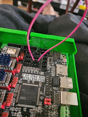
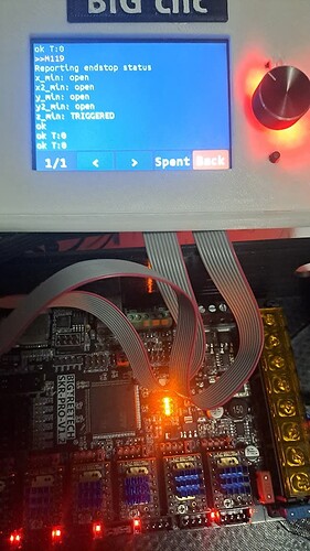
By bridging with a dupont, as in your photo, the LED lights up “more” but M119 has always been completely open (except z).
At this point, there are only two possiblities that I see as credible.
- Bad SKR board.
- Bad Marlin firmware build.
You note warnings from compiling firmware above, so one possibility is you’ve built bad firmware.
I suggest you flash the V1 SKR Pro firmware from the link below and try the M119 again with nothing connected.
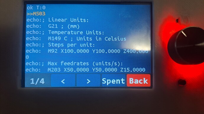
Show the M119 output with no endstops connected, as well as the M503 output as generated after you flash.
Based on that result, it appears you have a bad SKR board.
I had some very flaky behavior doing a Marlim firmware upgrade that required clearing the EEPROM. Apparently the memory locations where some parameters were stored changed and did not get cleaned up by flashing the firmware. I’d suggest running a “show eeprom contents” and save the result into a text file (so you have a record of what things were set to), then clear the eeprom and see if that makes a difference.
If it’s this (Possible, but I’m skeptical) then the M codes are:
M502
M500
Then reboot the controller.
Nothing… even after:
- M502
- M500
- reboot
the M119 returns all open, also after reinstalling the “standard” firmware the situation does not change.
All of this is pointing to a bad SKR board.
I’ll try to write to the seller, in the meantime if you have other ideas… I’m here! ![]()
Too low. With the jumper, it should go past 3, but if that isn’t reading triggered, the input lines on your SKR are probably bad.
Hi friends, here I am again.
Bigtreetech support, after making me waste endless time, came to this conclusion on the 2.29v value between S and G:
“Hello, this value proves that your power supply is insufficient and has nothing to do with the product.”
What do you think?
My power supply is ugly: 24v 60W but new and with everything disconnected, do you think it could be that?
No. The endstop circuit works off of the 5V circuitry, which is running on the 5V DC concerter on their board from your 24V supply. That doesn’t make sense to me.
They told me that a 10A power supply would be needed, perhaps thinking of a 3D printer even though I told them it was a CNC…
Final question:
Do I buy another card or buy another power supply?
If I had to change the card, since I can’t find it in local stores and I would have to order it on Aliexpress, are there any better alternatives than the skr 1.2 pro?
So with fluidnc you could have moved the input, etc. I highly recommend it. If you coukd get the board from ryan it is a great board at a great price. If you cannot. The tinybee is a great value. (I personally run it as i got it with a giftcard) ryans board comes with great drivers i do not have.
