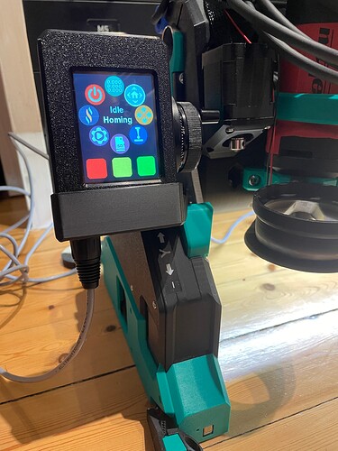
Just a stupid thought. There are esp32 boards available with usb-c and also the 2.8inch cyd is available with usb-c. Is it possible that they communicate via that connection.
Also I found usb-c to uart boards so using them on both sides should also work. And the cables could be cheap usb-c extensions and they are shielded already. Aliexpress
Another question is, is the connection right now only a problem when i unplug or plug in the pendant when the machine is running? Because i know you should not do this. Would it be a problem if i connect it without any protection? Just wire them straight together?
Sorry, @Fab_ster - We’ve taken you thread a bit off topic from your initial question.
Take a look at the post up above from @jono035, that’s what I’d advise you to make for the moment. I should really open a new topic to kick around the dual pendant/VFD interface module that was mentioned here.
Incorporate what is shown in that post up above, it’ll be better for you than what you had initially.
Would also be better than the stock setup.
That’s not how the UARTs are configured, so not without a bunch of work you’d need to do.
No, that’s not better.
There’s ESD concerns all the time, but leaving the pendant connected all the time is your best option.
@Fab_ster - I see you asked the same question on the FluidNC discord.
Have you built up your pendant adapter? How is your machine build going?
As I’m using the CYD Pendant that only requires 5V and not like the the M5 Dial 6-36V i will for now only use the resistors on the TX/RX lines.
That’s enough Protection for me right know as i know, don’t unplug shit while it’s powered.
I had no time the last couple of days but will start building again soon.
I also have to finish the table build for my lr4 before I’m able to do any kind of tests.
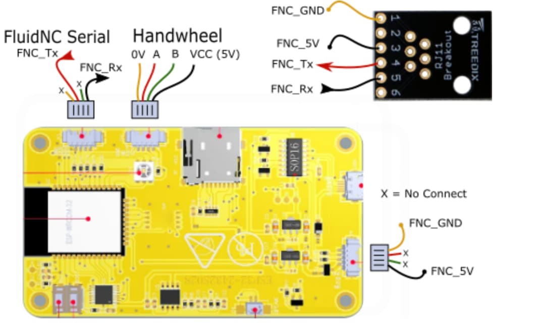
Another dumb noob question. in the FluidNC CYD Wiki it says that TX/RX should be connected to the upper left connector. Why not use the dedicated RX/TX pins on the lower right connector where the GND and 5V inputs are?
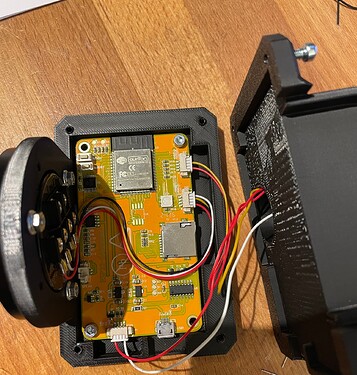
Had to wait for getting some Micro JST cables delivered. Encoder Pendant is done.
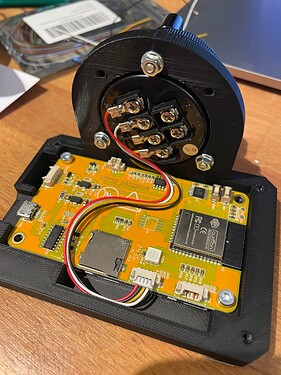
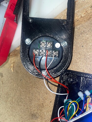
For the encoder i soldered on some ring terminals.
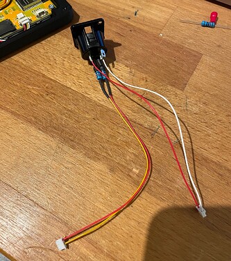
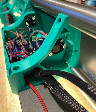
I soldered the 120ohm resistors straight to the XLR connector on the TX/RX Lines.
Don’t pinch those tiny cables when closing the Case!
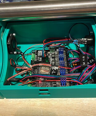
On the controller side i used a female XLR connector. There are two 120ohm resistors on the RX/TX lines as well.
The RX and TX lines get turned over on the Dupont connector on the Jackpot board.
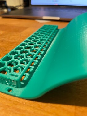
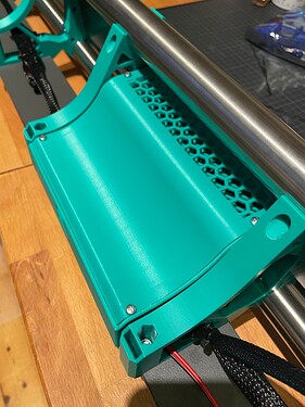
I integrated a slit for a filter element in the jackpot case lid so dust can’t enter. The 30mm 24V fan pulls the air out of the case.
Dang nice work!
I love that !
My Burly still wait to get all the Primo already printed parts (only 2 years now ![]() ) and the Jackpot pwb to take place, but for sure I want this wheel !
) and the Jackpot pwb to take place, but for sure I want this wheel !
@Fab_ster that’s great work, do you share your designs anywhere? I’d really like to make that jackpot case.
I will release all the files on Printables when my build is finished.
You can find all Files over at Printables.
Jackpot controller and power supply Case.
Have fun building it!
Thanks for the great work! I will definitely be printing the case today, looks like a great design! I already have the M5 dial… but I DO also have one of those encoder wheels, and that detent clicky-ness is pretty satisfying… I might just have to make one if I get bored enough lol
I really love thie design of this case and the concept of it! I’m working on the pendant for this CNC aswell, and I’ve gotten everything to work besides the encoder.
I’m using the capacitve CYD, and the touchscreen and jog works on it. Whenever I try to use the encoder though, the blue light flickers in response to every click, which seems to be a good sign. But the screen itself never responded to the encoder.
Could it be something with the code? I uploaded a pic of my wiring aswell. Any help would be appreciated!
I also noticed that OP is using the resistive version CYD, is there a working code for the resistive because I do have that screen on hand to test with aswell
Yes, that is the guide I am following.
Actually, I did not go into this blind. I have everything working except for the rotary dial. the OP is using a resistive CYD, which the wiring is different. I am using the capacitve, which works. The only thing that doesn’t work is the rotary dial. If anyone else has had this problem please let me know what you did to solve it. Thanks
