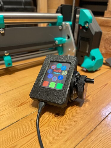
Not that I’m aware of but I’m happy to tell you what I’d do if you’ve got a goal for how bomb proof you want it.
I don’t think I’d bother with an isolated RS485 design unless you’re trying to achieve something specific with the isolation? The pendant is effectively floating anyway under normal usage so isolation will only realistically give you a little extra common-mode impedance/rejection at a LOT of extra cost/complexity.
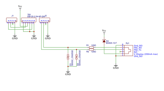
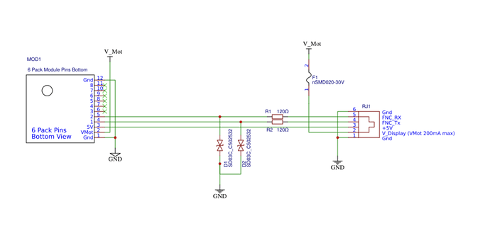
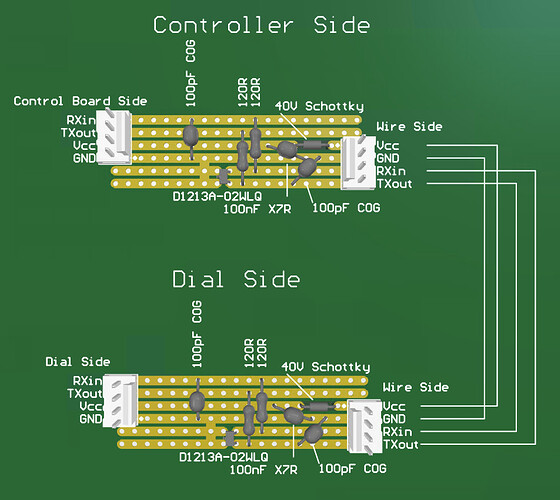
If you want to go full hardcore mode, I’d use an RS422 driver chip. Anything works but I’m partial to the TI parts, something like a SN65HVD1474. Those are neat because you can power them from 3.3V or 5V and their inputs are 3.3V compatible on 5V supply but there will be cheaper options. I’m a big fan of slew-rate limited drivers as well, but that’s a ‘nice to have’. Using it with an RJ style jack in 6P6C (RJ11 but with all 3 pairs) or 8P8C (ethernet) and 3/4 pairs works. 1 pair each direction and 1 pair for power. 120R terminations at each the receive end of each pair, I like doing those as 2x 60R resistors and a 100nF cap in the middle to 0V, but for 422 it doesn’t matter. Also 422 doesn’t ever turn off its drivers under a valid operating condition (unlike HD RS485) so no defined state termination is needed. If doing half-duplex I make one termination defined state (so something like a 220R terminator with something like 680R to +V on one side and 680R to 0V on the other such that the entire network still maintains 120R impedance but when open-circuit idles with just enough voltage to keep the transceiver in a valid mark or space condition, whatever the normal ‘idle’ for the line is).
You’ll need 3.3V or 5V power on both sides for the driver ICs but that could easily be an appropriate LDO off the full voltage. Just keep an eye on current draw as driving ~3-4V into the termination resistors is a notable amount of current, 30-40mA potentially.
If using multiple pairs for power, I put Vcc/0V on each pair, rather than Vcc on one pair and 0V on the other as that gives you the lowest inductance and highest capacitance per unit length.
I don’t usually bother with external ESD protection on those drivers as they’re already pretty meaty both in terms of ESD capability and input voltage range on the pins, but then I’m usually designing for fixed installs or I try to use scoop-proof connectors that have make-before-make grounds like the Harting industrial series.
If you don’t want to go that hardcore then for short runs I don’t see anything too bad about using the GPIO directly, but I’d definitely want a bit more protection/filtering on it.
Regardless of 422, GPIO, whatever, I’d add a ferrite bead to every signal (even 0V) near the connector and then either a direct to ground connection or an appropriate cap (100nF for power, 100pF maybe for signal) to a ground plane, well attached, 2 vias per pad etc. Sizing the FB and the cap depends on the signals you’re trying to let through, but at 10MHz anything in the 100R @ 100MHz range is probably golden. Having equal FBs for every pin helps with avoiding a common-mode to differential-mode transform caused by different impedances on each pin.
Then an ESD suppressor like the CD143A-SR3.3 I mentioned above.
Then potentially extra signal filtering if you wanted to have better control over the lower frequency parts of the signal set with an f(-3dB) frequency around a decade above the highest preserved content, although the FB and cap is probably more than enough for this at 10Mhz for a 1Mbd signal.
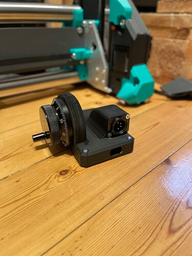
If I were using RS422, I’d probably stick with an 8P8C ethernet socket for my own use, I know not to plug it into an ethernet socket. For wider use I’m not as much of a fan of them because a 422 driver plugged into an ethernet socket will happily smoke the isolation magnetics by stuffing 5V DC down it. You can avoid that by changing the pinout but then that means you can’t use OTS patch cables. If you use shielded sockets then you can use shielded cables, too. The shielding on them is actually pretty crap due to the limited way the socket interfaces to the plug but that’s likely to get you a make-before-make ground connection and provide good passive ESD protection.
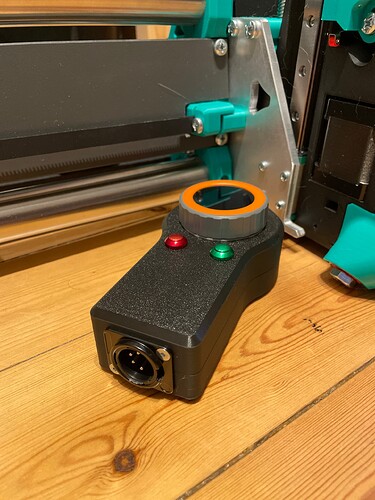
As for connectors, the venerable DB9 works pretty well here. They’re uncommon enough now that cross-mating isn’t a huge issue and they’re all shielded (somewhat poorly) but in a way that makes it all but impossible for the shields to not have at least briefly connected before a contact is made. Not scoop-proof, though. Same situation with the good old DIN connector, too. That’s what I used on my MPCNC. In both cases you can also get pre-made cables relatively cheaply that use shielded/screened cable, although none of it’s all ‘that’ great.
Lemo make some pretty good small signal connectors but they’re spendy.
Harting modular, Bulgin Buccaneer, an M12 automation connector, any mil-spec style connector if you want to be hilarious. Actually, I intended that to be a joke but a lot of those have cheap compatibles available via Aliexpress too, I noticed the other day. I found the SP16 and similar connectors on Aliexpress that look like a knock-off version of the Amphenol C16s or Bulgin Buccaneer series that I used to use and love when I was doing port automation equipment. Same thing for the Lemo connectors, automation connectors, all sorts.
So probably not as much help as I might have thought with the connector but perhaps looking at affordable pre-made cable assemblies and working backwards could be a good idea. The automation connectors are probably the best bet there, actually, as they’re pretty compact and commonly have right-angle molded versions available. Technically it’d be best to have twisted pairs for RS422 but in the range of 1-10m it really isn’t going to matter absent some REALLY gnarly noise issues.
![]()
