Okay, so I don’t have the incredible creativity of @bitingmidge (those fenders… just wow!), or the incredible design and remix skills of @DougJoseph (where do I even begin…), or the incredible engineering skills and generosity of @vicious1 (creating the amazing LR3 and then putting the plans online for free? Any thanks seem inadequate), but here is my humble contribution to the LR3 community.
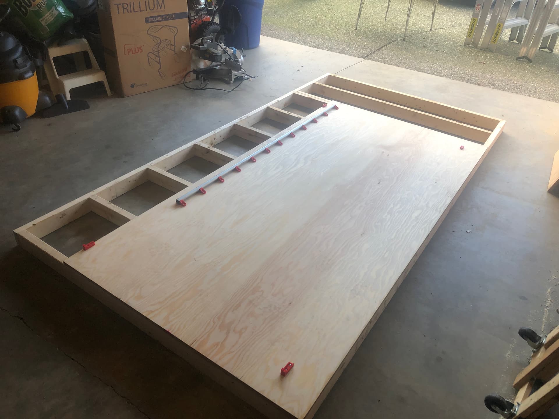
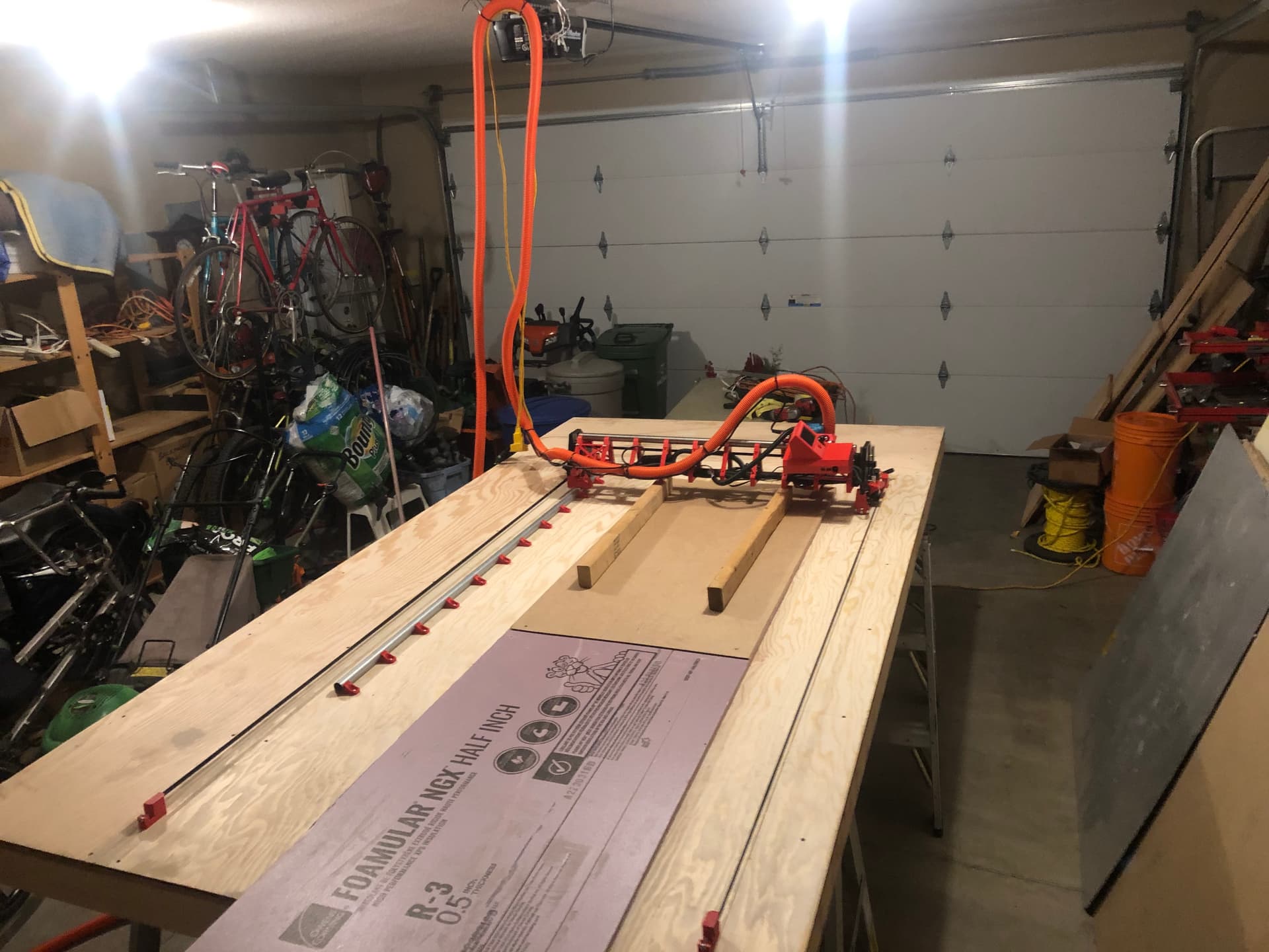
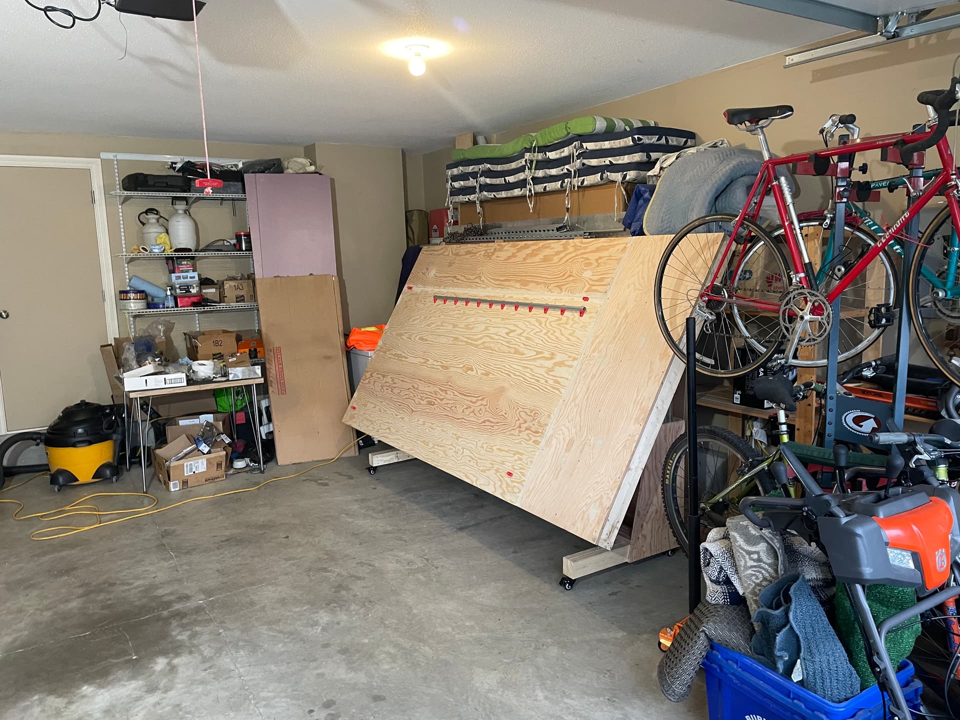
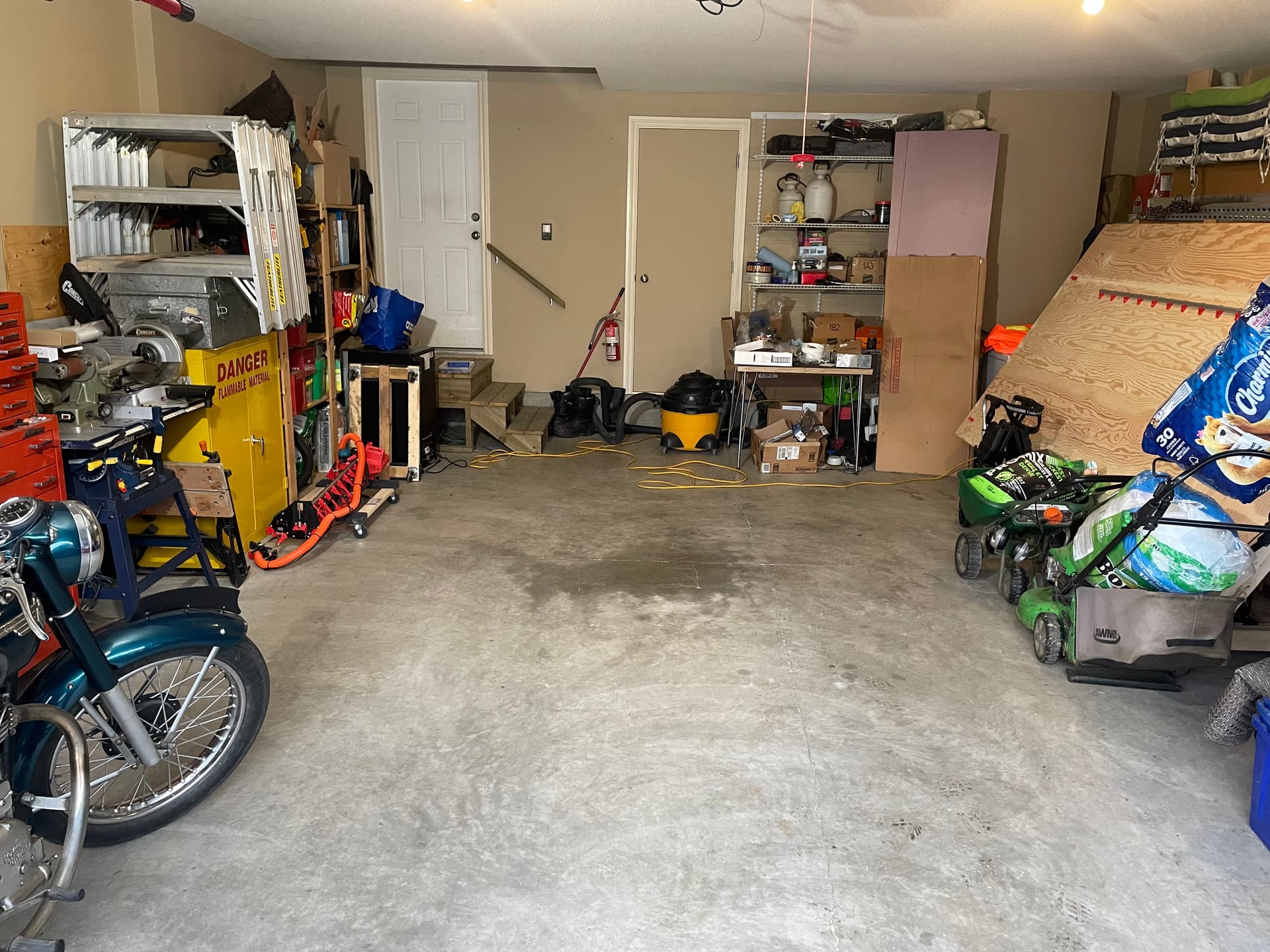
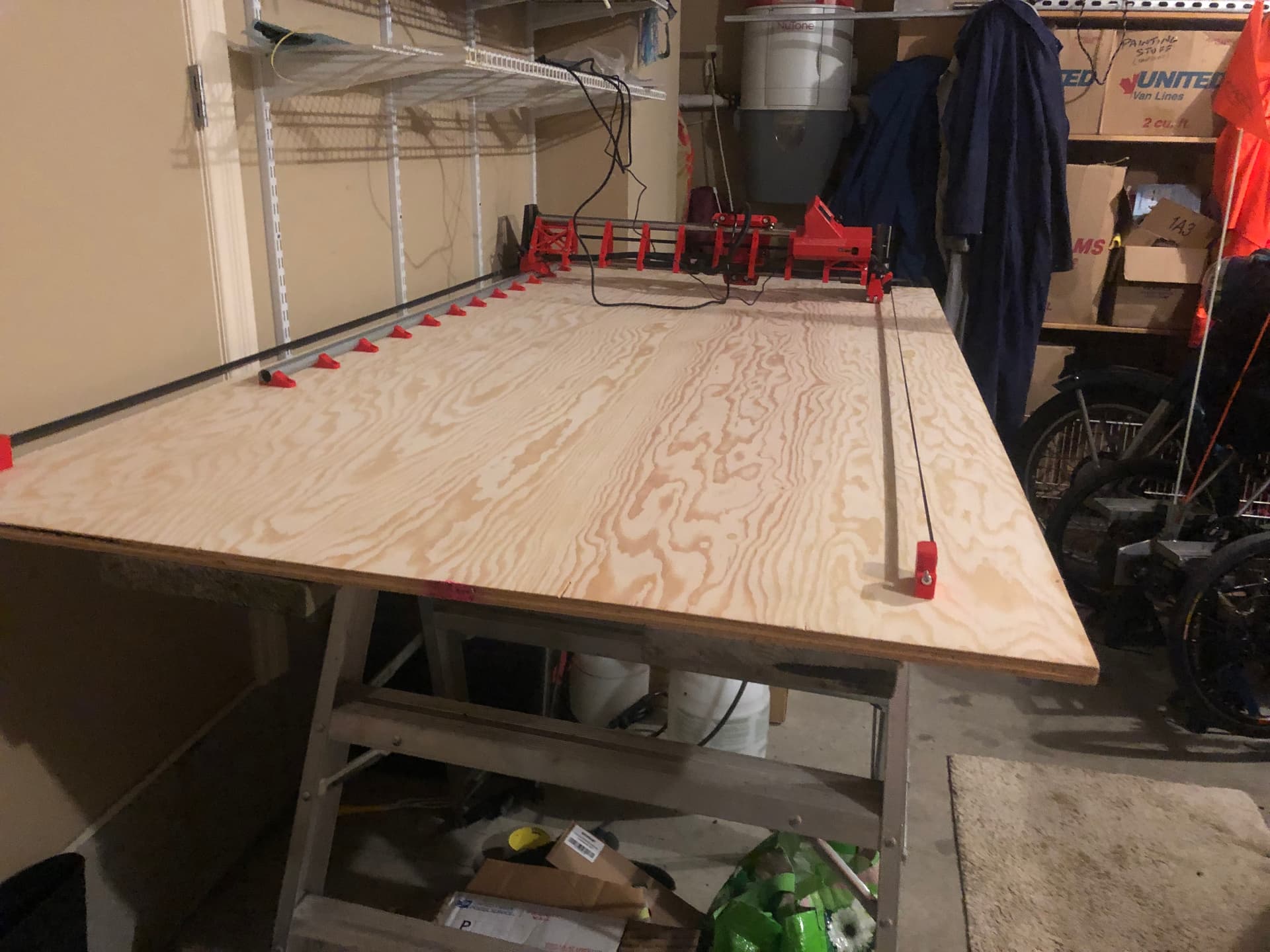
So my problem was that my full size (63" x 120"“) LR3 table took up almost my entire garage, and my wife was not happy losing her indoor parking space on a permanent basis. It was built from 2x4s and 3/4” plywood, and weighed a ton (well, around 200 pounds). I was supporting it with a few sawhorses, and trying to move it off the sawhorses and lean it against a wall was an adventure that I didn’t want to attempt more than once.
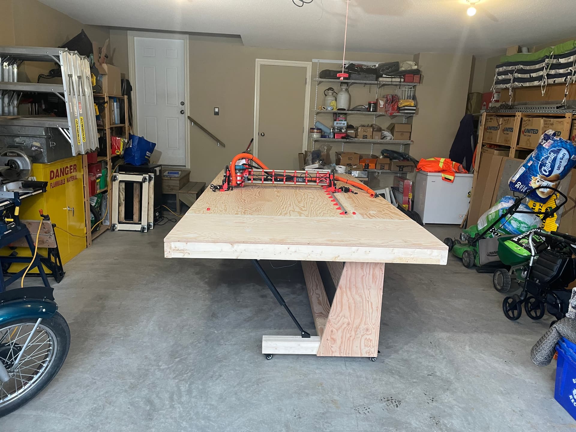
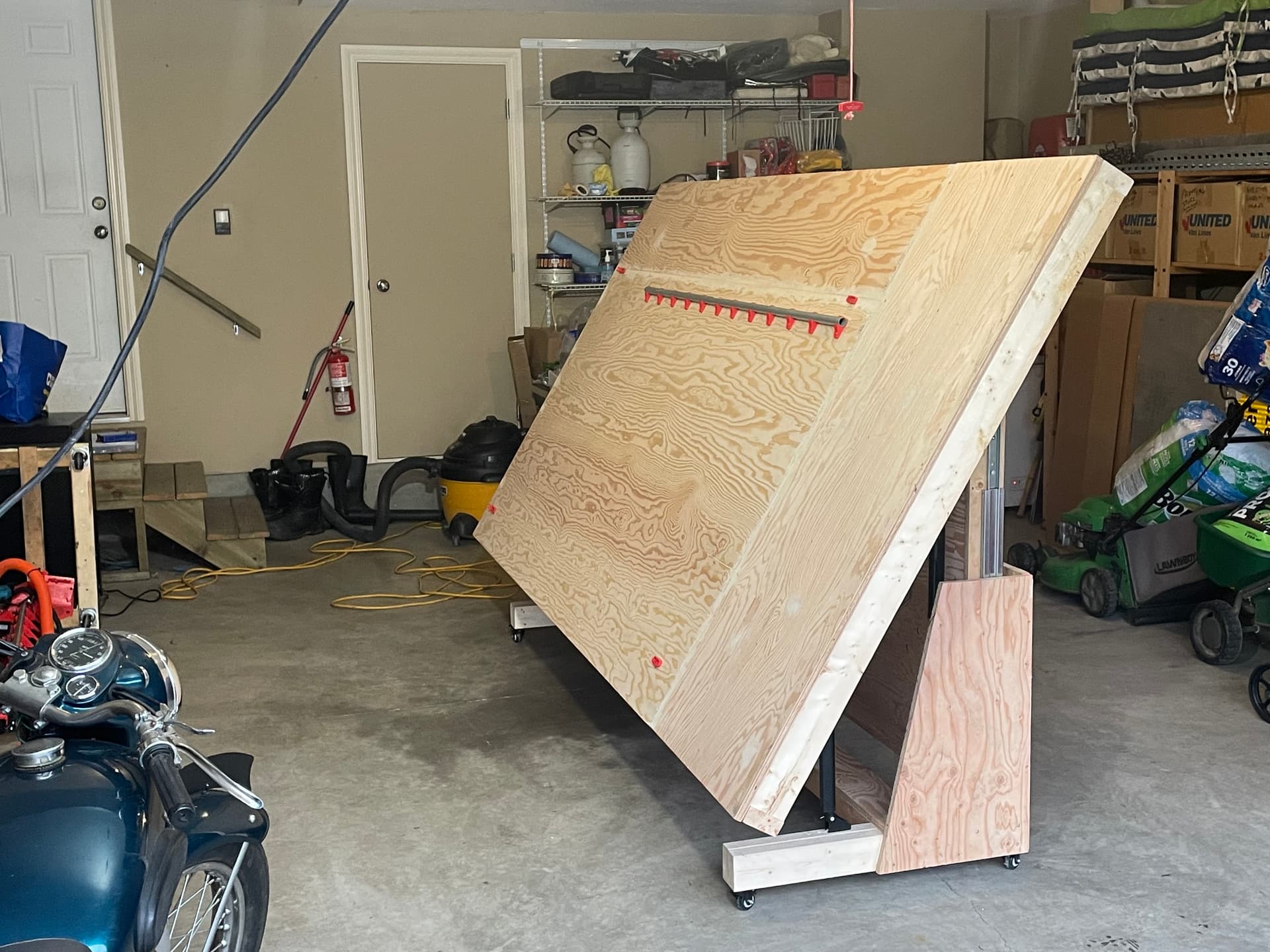
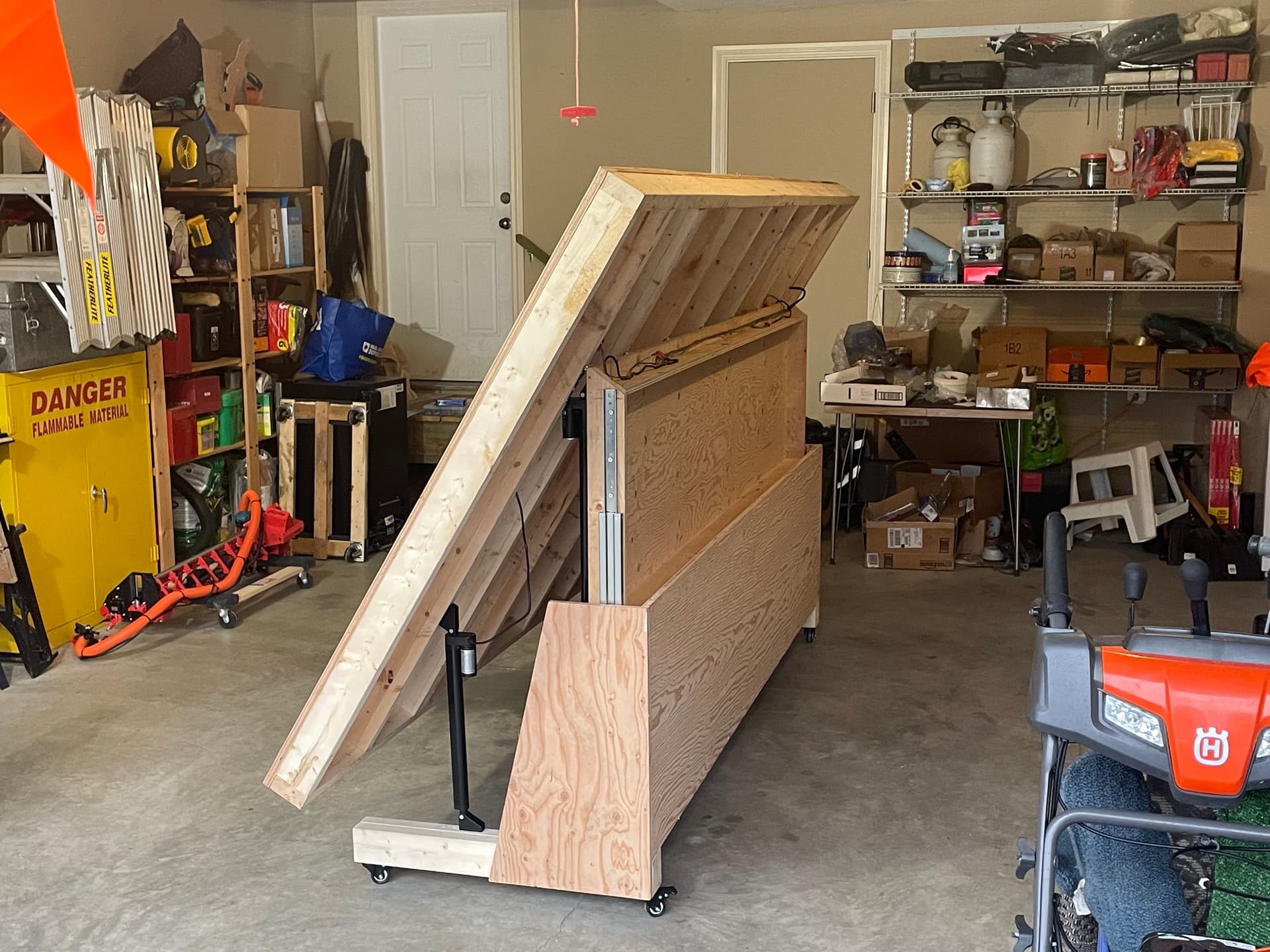
So my solution was to build a table base that could allow the table to tilt on an angle so that it took up less floor space, and then could roll off to the side of the garage. As my Fusion 360 skills are sorely lacking, I designed most of it in my head and on a few napkin sketches, and with a bit of trial and error, I came up with a (mostly) successful prototype.
It uses two 20" linear actuators for the vertical lift, and two 14" linear actuators for the angular lift.
I’ll post some details of the build in a future post, with Bill of Materials, dimensions, cost, etc. if anyone is interested. Hopefully this idea will help out members of the community that are short of floor space and don’t have the free wall space to build a hinged table on a wall.
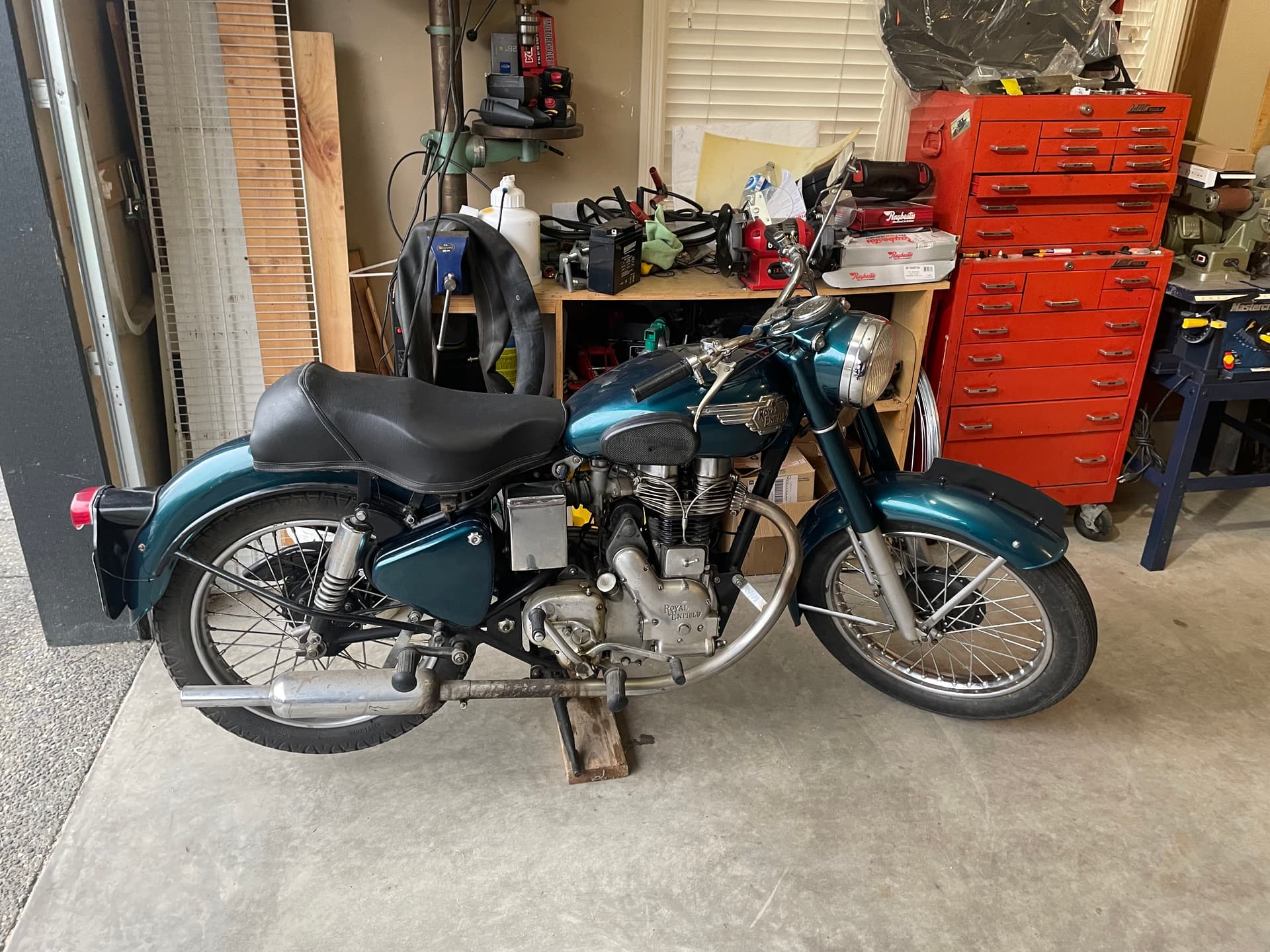
BTW, in case anyone was wondering about the motorcycle in the above pictures, it is a 1955 Royal Enfield 350cc single cylinder.
¾” lag screws (x16) for attaching actuators to plywood/lumber
#12 x ¾” wood screws (x16) for attaching sliders to plywood
#8 x 2 ½” wood screws (x 12) for attaching lumber feet together
#8 x 1 ¼” wood screws (x 20) for attaching plywood pieces to lumber and plywood
#10 x ¾” wood screws (x 42) for attaching hinges to plywood/lumber
1 bottle carpenter’s glue
Note: links are for Amazon Canada and Home Depot Canada (prices are in $CDN), but US and other countries sites should have identical or similar items available (probably at a lower cost)
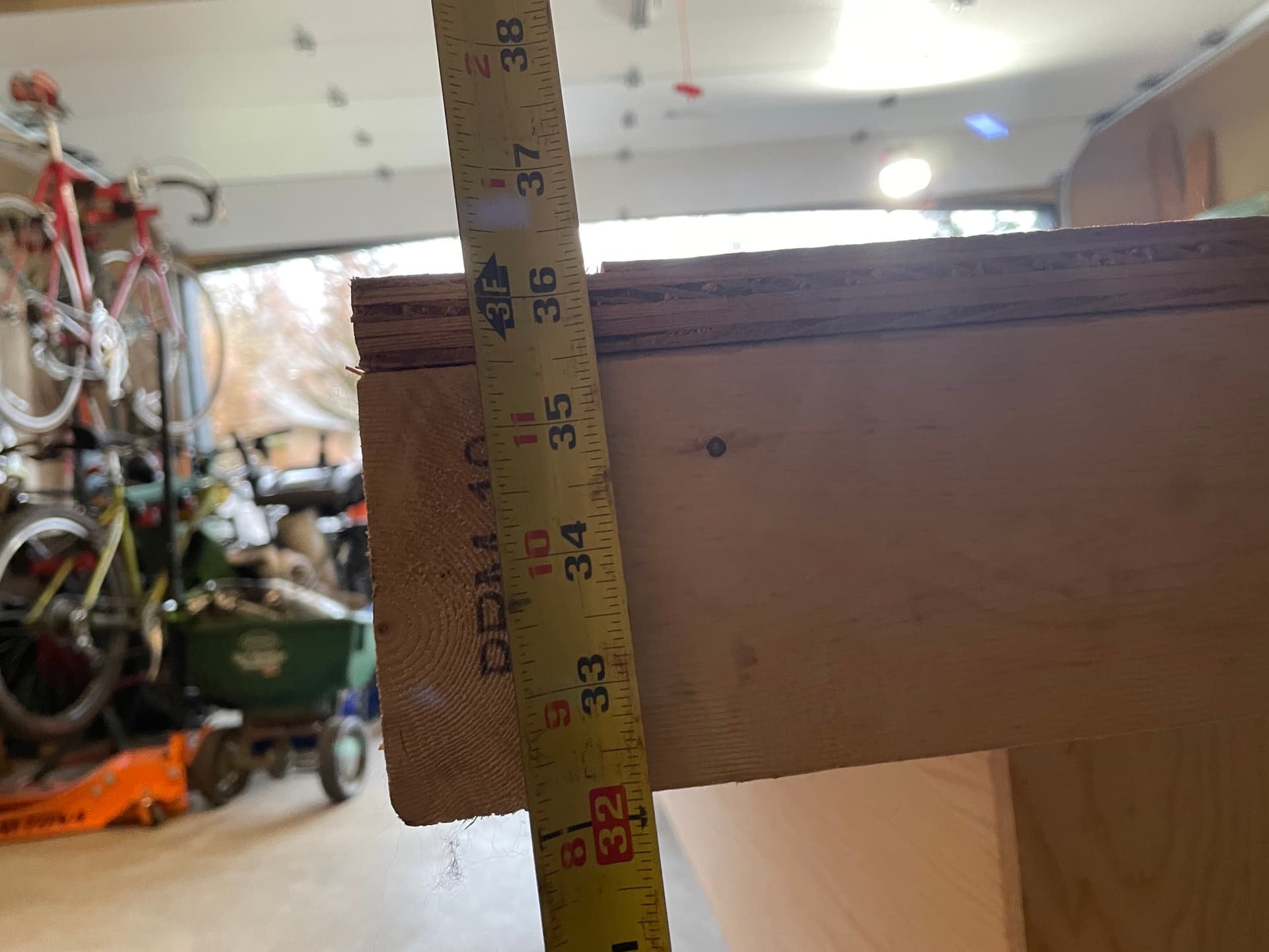
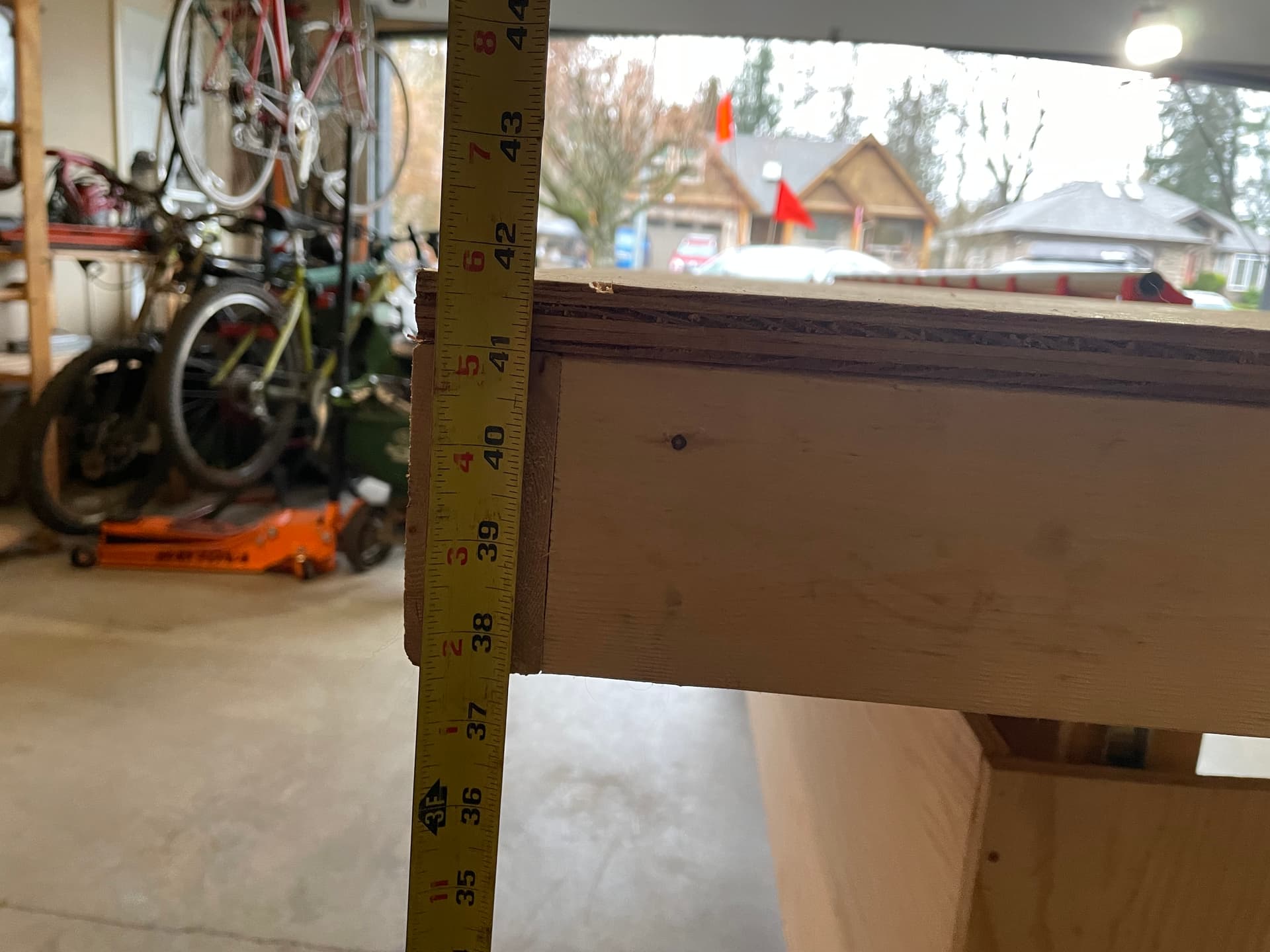
AT the lower end of the range, it is 36" high (32" to the bottom, so if your table thickness is not 4" then total height will vary). Perfect for loading heavy materials onto the table.
The time to lift and retract is a respectable 64 seconds fully up and 61 seconds fully down. So only about a minute to tilt the table and move it out of the way, or to get it flat again after storage!
If you are talking about the fact that the CNC is inset from the table edge by quite a bit, that is because I originally built the “Little Red” CNC on a single sheet of plywood for testing and troubleshooting purposes.
The CNC will be expanded to a full size “Big Red” version shortly, so when I built the full size table top, I simply re-used the existing plywood, and it ended up that the rail was inset by about 15". It will be moved to the edge when I get my longer struts cut.
Awesome stuff! I was just looking for something like this that would allow me to put a full sheet LR4 in a workshop with limited space. A few questions if you don’t mind:
Is there any design reason for the folded table not to be fully vertical? Or is it because with available hardware that was the max and it’s ok for your use case?
In order to get it fully vertical, the pivot point would need to be in the center of the table surface. This leads to a couple of issues.
Firstly, the unsupported (upper) section would be the same size as the supported (lower) section, so when horizontal, weight on the the unsupported section would have a lot of leverage, and I felt the resultant forces may be too much.
Secondly, I wanted the horizontal base to be shorter on one side, so I could get it closer to the wall when stored. If it pivoted in the center, I would need those legs to be much longer on the back side.
Thirdly, with the shorter legs on the back side, I needed to keep more weight on the front base legs to keep it from tipping if excess weight was placed on the back section of the table surface (again, leverage). This required placing the tilt actuators on the front legs instead of the vertical section. This placement excludes the possibility of titling completely vertical.
Note that placing the tilt actuators on the legs also requires preventing the angle from not going “over center” when the tilt actuators are fully retracted, otherwise they won’t push the table outwards when extending. This required a bit of trial and error when placing the lower bracket of the actuator to the base leg.
Sadly no. This was mostly designed in my head, with a couple of “napkin sketches” along the way. As my table size is different than most, any plans would have to be adapted to fit other user’s tables.
Probably the best I could provide is some additional photos of the build to provide some visual details. You would have to reverse engineer things from there, and adapt to fit your table dimensions.