Wait a minute…I don’t think the genuine has a cap on the boot pin. Is that slowing us down?
They are so small you can;t tell…
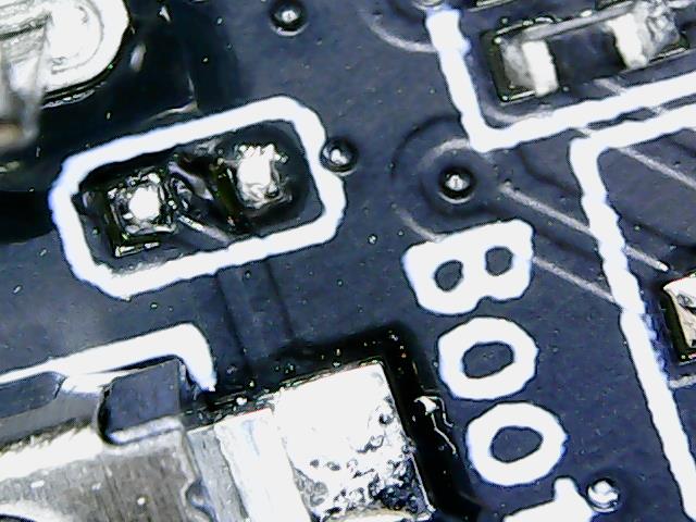
boot side
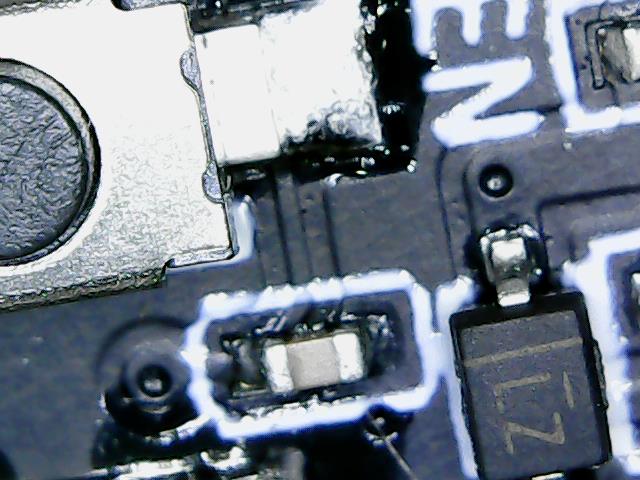
En side
Until you zoom in.
Boot has the cap removed.
Definitely something interesting going on there, I wouldn’t have expected to see a significant difference in those pins.
I wonder why IO0 is jumping high there… That might just be when code starts to execute and it’s being configured as an output. That would make sense with EN reaching ~1.5V which is likely its threshold voltage.
The faster rise speed on the EN pin will just be the single 100nF cap instead of 2x. That’s almost perfect step response for a 10K/100nF cap.
Ah, interesting. That’s a bit of a smoking gun, there. The schematic being correct for the layout but there will be a separate BOM document to check that shows whether parts are actually fitted or not.
Okay so I will pop it off and see what happens.
Is that this one with the question mark?
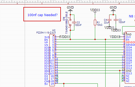
I need to pop that tiny little booger on a booger off 100 boards now. That is gunna suck.
I also need to dim that LED.
Small, sharp side cutters will make quick work of that 
Drop of really dark fingernail polish…
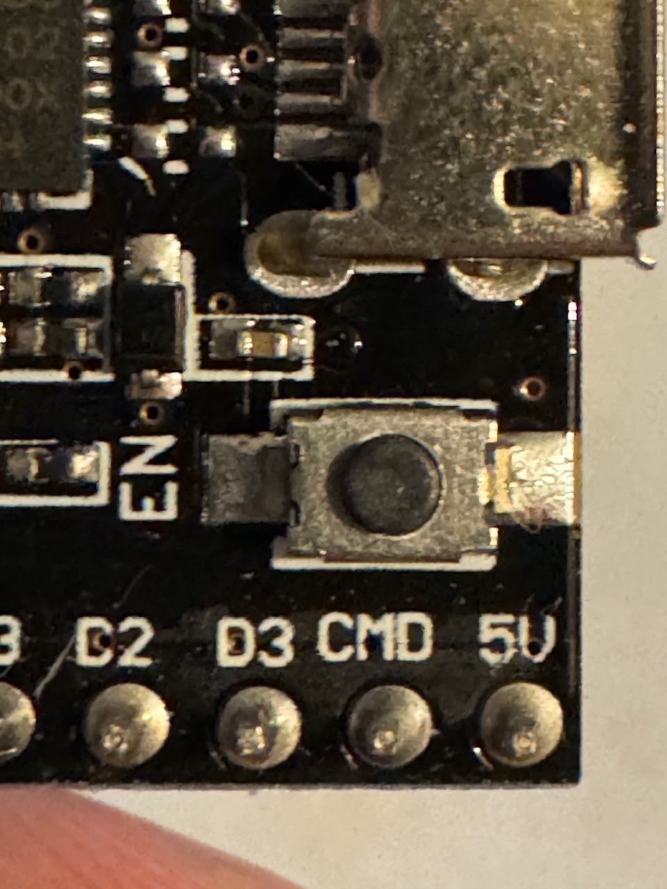
it is really close to the button but best believe I will try that. probably even a tiny screwdriver.
I just checked a couple my clones are all missing that boot cap, but the pads are there as well
Yeah, that’s a nice trap to be aware of.
This is one of the ambiguities that you run into with schematics. The schematic often refers to the layout, specifically, not the actual final assembly.
With version control systems, we typically have a tracking number for the schematic which will be correct for the layout, we’d have another tracking number for the layout/unpopulated PCB. There would then be another tracking number for the BOM which would be linked to yet another tracking number for the assembled PCB.
There are good reasons for doing it like that, in that often it follows the workflow: Schematic gets made first, then layout, then after testing the assembly gets finalized (which is where you’re at now).
So in your case, you’d have a BOM that matches the final assembly and would not contain that capacitor.
You CAN do this with schematics, but given that you’re giving BOMs to the contract assembler, it needs to be done on the BOM as well, so often it’s only at the BOM level anyway, with the schematic remaining as a single schematic that needs the BOM to be correctly interpreted, etc.
The EN needs one, the Boot is the tricky one that doesn’t
OMG that is amazing.
ah…sorry, I misread your picture earlier. I thought you were looking at the EN side
I am going to try and figure out what they are on the jackpot and match them. I will post my math up here when I do it.
China goes on Holiday soon If I want to order another batch I need to do it in the next day or two. Also need to fight with the pricing to see if I can get it to Mouser prices at least.
Oh and the UART pads on the back
OMG the Jackpots are going to be freaking amazeballs now…I did not think they could get any better,