A few conversations in the Discord seem to suggest it should be fine with only the 4MB partition

2 Likes
Ouh oh…that is not good. I must have messed something up.
Did you ask the Fluidnc guys? Maybe they have a work around.
Not normally. The chip doesn’t actually ‘know’ how much flash it has, it just starts at address 0 and executes various jump/branch codes from there. Unless there’s something really funky with the way the chips lay out the flash space (which is somewhat of a throwback to older 8/16 bit designs, mostly), then the address block that the flash is at should just be one big chunk. Compiling for 4MB and flashing onto an 8MB will just mean that all the firmware will fit in the first half and be jumping back and forth. The other way round doesn’t necessarily work because the flashing tool will try to flash and verify the extra 4MB, which won’t work because it doesn’t exist.
Edit: Some workflows (the old Atmel micros, for instance) have checks where you have to specify the correct chip model and it will get verified before flashing, but I don’t think that’s the case here. I think the flash is external on these so is part of the assembled module, not part of the chip itself.
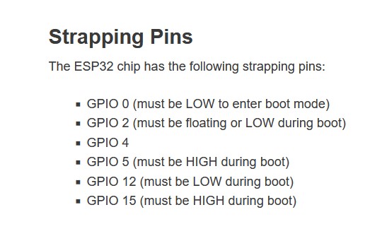
This seems to point to one of the several boot pins is floating somehow that should not be?
Maybe a poor choice of a component. That $ss thing is really sitting wrong with me. It seems odd. When the big batch of Genuine Espressif boards gets here we will really see if it doesn’t happen with them.
1 Like
Time to bust out the scope again when you’re back in on Friday.
Okay I am out of ideas.
The new boards $ss seems to be perfect, they flash perfect in the web installer, and work perfect.
The one issue I am worried about is that they do not boot right on USB only. I tested all the pins any that should be high are and any that should be low are.
I put it on the scope checked a bunch of pins and they seem identical to the Espressif ones other than they do not start spitting out data on pin4.
If I have it on USB no jackpot no SSID, Use the fluidterm (ctrl+r) to reset it and it boots fine. Put it on a jackpot and it is perfect with or without drivers. (something is just barely wrong???)
I checked all the pins for resistance to ground. On the V1 board the pins are ~11M, and on the Espressif board they are ~12M. That seems okay (but why is there a difference?). The Enable pin though…that one is different. On the V1 board, it is 11k, the espressif is 80k and keeps counting up higher and higher.
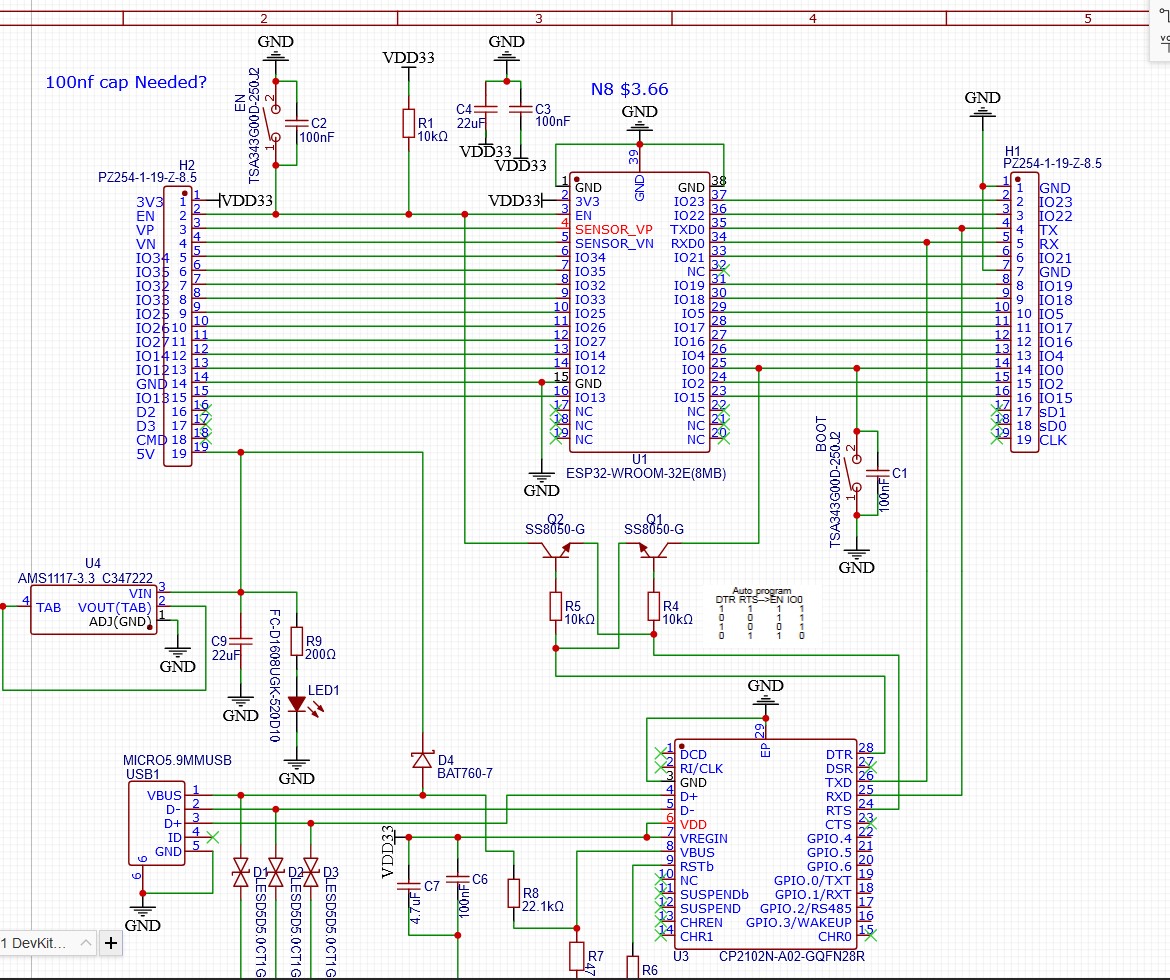
Espressif - https://dl.espressif.com/dl/schematics/esp32_devkitc_v4-sch.pdf
The only thing we changed on the enable line is that one cap, so I soldered one on…no change.
So close I would have no issues using these with the JAckpots but I want to know what is going on before I do that.
That’s unlikely to mean anything. I wouldn’t personally read much into using a resistance tester on a powered or un-powered board. Instead I’d be looking at the voltages during operation. The ‘counting up’ you’re seeing is probably a capacitor charging… It’s a little strange that it’s that different given how similar the schematics are, but it’s also not really a ‘good’ way to test anything so I wouldn’t read too much into it. Ultimately the strength of the pull-up doesn’t matter unless it’s changing the voltage because the voltage is what the microcontroller will be making decisions based on. If the pull-up was too weak, you’d see it taking a long time to reach the correct voltage or you’d see ‘dips’ in the voltage when the microcontroller changed state or similar. If the pull-up was too strong, you’d see things like the reset button or an external reset circuit being unable to pull the voltage low enough to reset the micro etc. The best way to look at it is to look at the behaviour.
Are you looking at those pin starts on boot and triggering the scope you can see if they’re changing at all during startup? Sometimes it can be issues where a circuit isn’t staying under control during the boot process. I’m not sure why that would be happening here given that they’re so similar, schematic wise, but that’s kinda the thing with troubleshooting: If everything looks fine but doesn’t work, either something isn’t what it looks like or the evaluation that everything looks fine is incorrect. Either way, you’ve gotta start poking around at things and just trying stuff until you find something. Ultimately just scowling at it and saying ‘Why don’t you work?!’ doesn’t do much.
1 Like
It might be a real pain to do, but one thing would be swapping the modules between a V1 board and an Espressif board. If the issue chases the module, it may be something subtle with different versions of the module itself. If the issue stays with the board, it’s something on the board itself.
2 Likes
Yeah, as @jono035 says, you’re just charging up the cap with your DMM.
Are these the newest (V4?) release of the Espressif module? I know the latest versions have a bunch of minor erratta fixes.
Are these still using the AMS1117-3.3? Honestly, if so the first thing I’d swap would be to put a better regulator on one of these and see if it then works correctly on USB.
1 Like
Potentially, but ultimately I’d probably investigate that further first rather than replacing it. A scope probe on the 3.3V rail on startup will show you if the regulator is having any issues. If it’s failing to hold regulation, it’ll be pretty obvious by dips/overshoots on the 3.3V rail. If the 3.3V rail is solid, there’s not really any way that the regulator is likely to be influencing anything else.
1 Like
Why would the serial monitor trigger it to work right?
Trying the scope on en, 3v3, io0 and io4. zooming in to look closer.
If it’s startup regulation (when you first plug in the USB cable), that isn’t the case when you restart with the serial monitor. You then reboot while power is steady, the system is happy.
That’s just a crappy theory, and the right thing to do is to put a scope on it as we’ve described.
2 Likes
To add to that. Same thing happens when powering from the 5V pin.
Lemme grab a couple shots. 3v3 is super solid.
Well, that’s the important part of troubleshooting: The ‘I wonder…’ or ‘maybe it’s this…’ part. 99% of the ideas will be wrong, but if you knew which ones without testing them, why wouldn’t you just go straight to the right one!
There’s a lot of difference between a cold and warm boot. With a cold boot, the voltage rail might still be rising or might not be stable yet. In bigger designs there might be other timing things going on with loads appearing on the rail that coincide with startup. There might be registers in the ESP32 that have random content and are being initialized incorrectly.
With a warm boot, you’re really just taking a circuit that’s at steady-state and resetting the program counter to the initialisation point. It’s often no different to triggering an interrupt in the firmware etc.
‘Same thing’? Sorry, I struggle a little to follow comments like this where they rely super heavily on the context from other comments. Can you just summarize the issues you’re seeing and when they do/don’t occur?
1 Like
The way I’m reading this is if you power up by connecting just USB, the module doesn’t make it all the way up to presenting an SSID in AP mode.
You then tried just powering the board with a 5V and GND pin (Bench PS?), and the same thing happens?
But with all the boards, if you put them in the jackpot and power up, they boot just fine and happy?
My guess is the extra pullup on the Jackpot is needed and that if you were to jumper in the same pullup resistor in a breadboard setup they will boot fine and happy.
2 Likes
Definitely seems plausible.
It’s also potentially worth trying plugging into the external 5V power supply with it already on if you’re turning it on and off at the supply currently. Some of them have a pretty slow turn-on ramp up.
Also might be worth trying to take a look at the values on the components, if they’re visible. It’s not unheard of for assembly problems to lead to the wrong passives being fitted, so all 10Ks being 10M or something weird like that, although I’d have expected that to be visible in the Enable pin state.

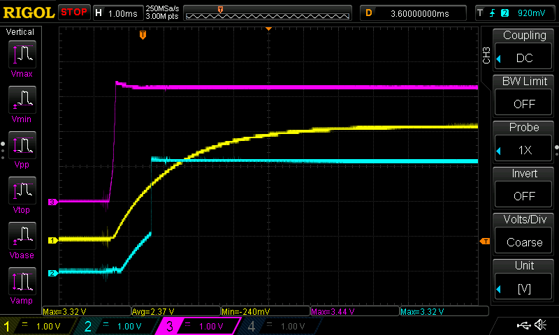
Interesting. Top is V1 bottom is espressif.
Purple is 3.3V
Yellow is Enable
Blue is io0
What pin am I missing on boot?
3.3 is looking good to me, maybe even better on the V1?
Enable is identical
Maybe io4 is the one to watch edit- nope io4 is way later.
What’s the timing there? Is gpio0 being pulled high too slow compared to genuine?
Can you verify whether it’s in boot loader mode?