For fine tuning you can use the same gcode/method as for squaring, M666 and save with M500. The process is similar, just replace Y with Z.
I think it is best to first try to get as close as possible by adjusting the end stops manually, and then fine tune in the software
1 Like
Hi guys,
I have a dilemma; during drawing the 4 corners with the squareness test from (G-Code Test Pattern Generator) I noticed that the pencil touches some area’s of the surface while traveling. My assumption is therefor that my “bed” is not flat. So I would like to do a surfacing action with a dovetail bit to make it flat.
Also, I know that my gantry is not perfectly perpendicular to the bed surface. I used a piece of scrap wood and a stack of playing cards to get both Z-endstops nearly identical in the center of the table, but it’s not perfect.
I now could use advice which action to perform first;
- Should I first tram the LowRider (using the instructions from @DougJoseph; https://www.youtube.com/watch?v=NkXW_XVOLD4), and then modified for the SKR board. But then I have the “risk” of tramming against a non-flat surface
- Should I first flatten the bed surface with a dovetail bit. But then I have the risk of making grooves because the router bit is not exactly parallel with the surface.
I trammed, then surfaced
2 Likes
Level the Z first. If your bed is really bad use any straight edge you can to find the most flat spot side to side (X- and X+). Use that to level the Z (endstop offset in firmware), and lightly surface your table. Then you can tram your router if you really need to (you need a milled flat spot to swing the tool). Then do a final surface of your table.
The amount of times you check these things and how many you do are totally dependent on the type of projects you do and how “perfect” you want your machine.
2 Likes
Thanks for your advice. I will do that.
I have found with 3d printing that making sure everything is as good as it can be, prevents a lot of frustrations down the road ![]() So, I’m willing to put some time in this.
So, I’m willing to put some time in this.
Hi Guys,
Another question regarding tramming with the Marlin software;
I have written a small gcode to prevent me from typing commands in the small tft screen;
; Manual tramming gcode
; x max 1045
; y max 1823 (half = 911,5)
G28 ; home all axis
G0 Y911.5 X100 ;move to halfway table, 100 mm off X-edge

G38.2 Z0 ;touch to table
G4 S30 ;wait 30 sec to note values
G28 Z ;home Z

G38.2 Z0 ;touch to table
G4 S30 ;wait 30 sec to note values
G28 Z ;home Z
etc. In total 5 times at X-min + 100mm and 5 times at X-max - 100mm
My idea was to use the G4 wait command to go into the menu and note the Z-value. But I now run into the issue that while “printing”, I cannot access the X - Y - Z coordinates.
Some screenshots;
during operation;
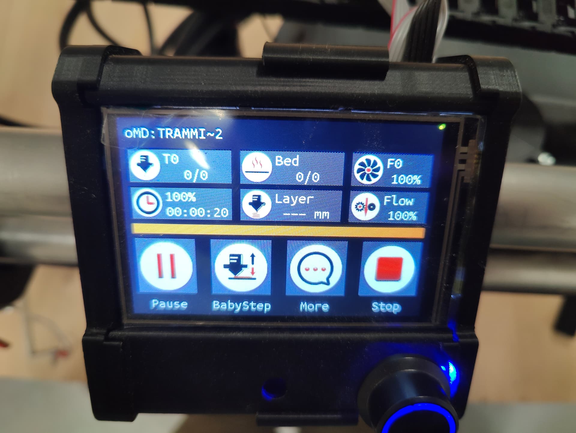
The “More” menu;
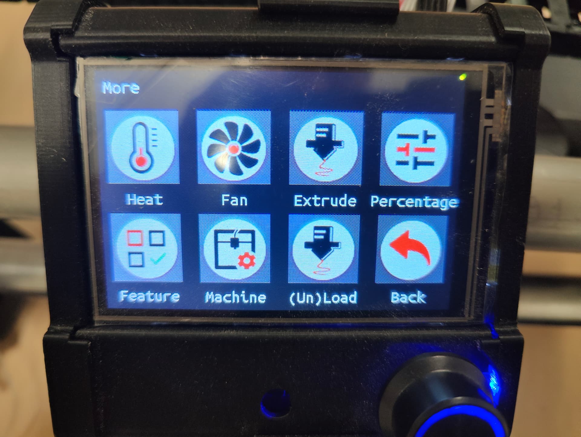
In more: “Machine” menu;
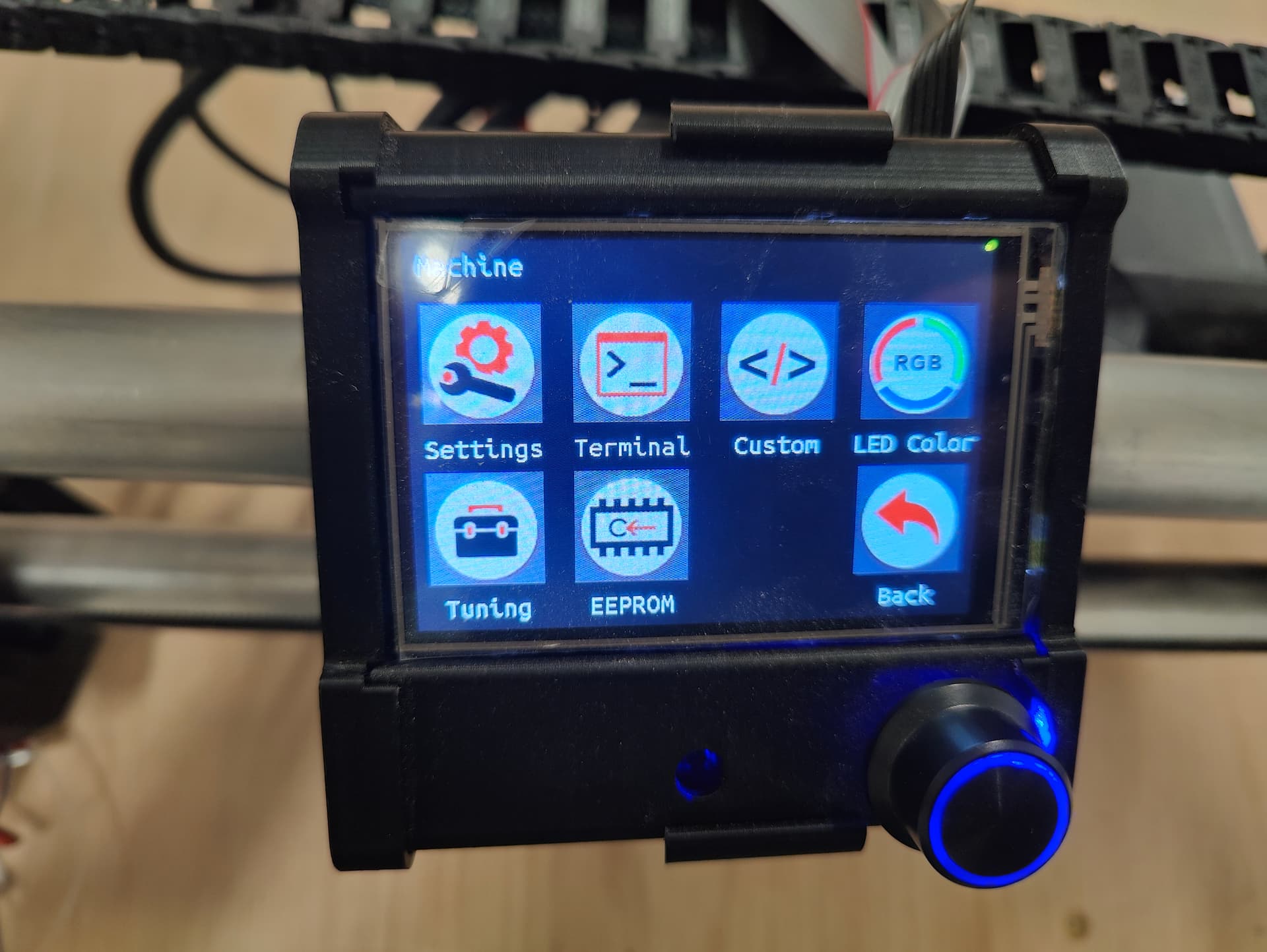
The screen that i’m actually looking for with the X - Y - Z position in the top (this one is in “Move”, which is not available during operation);
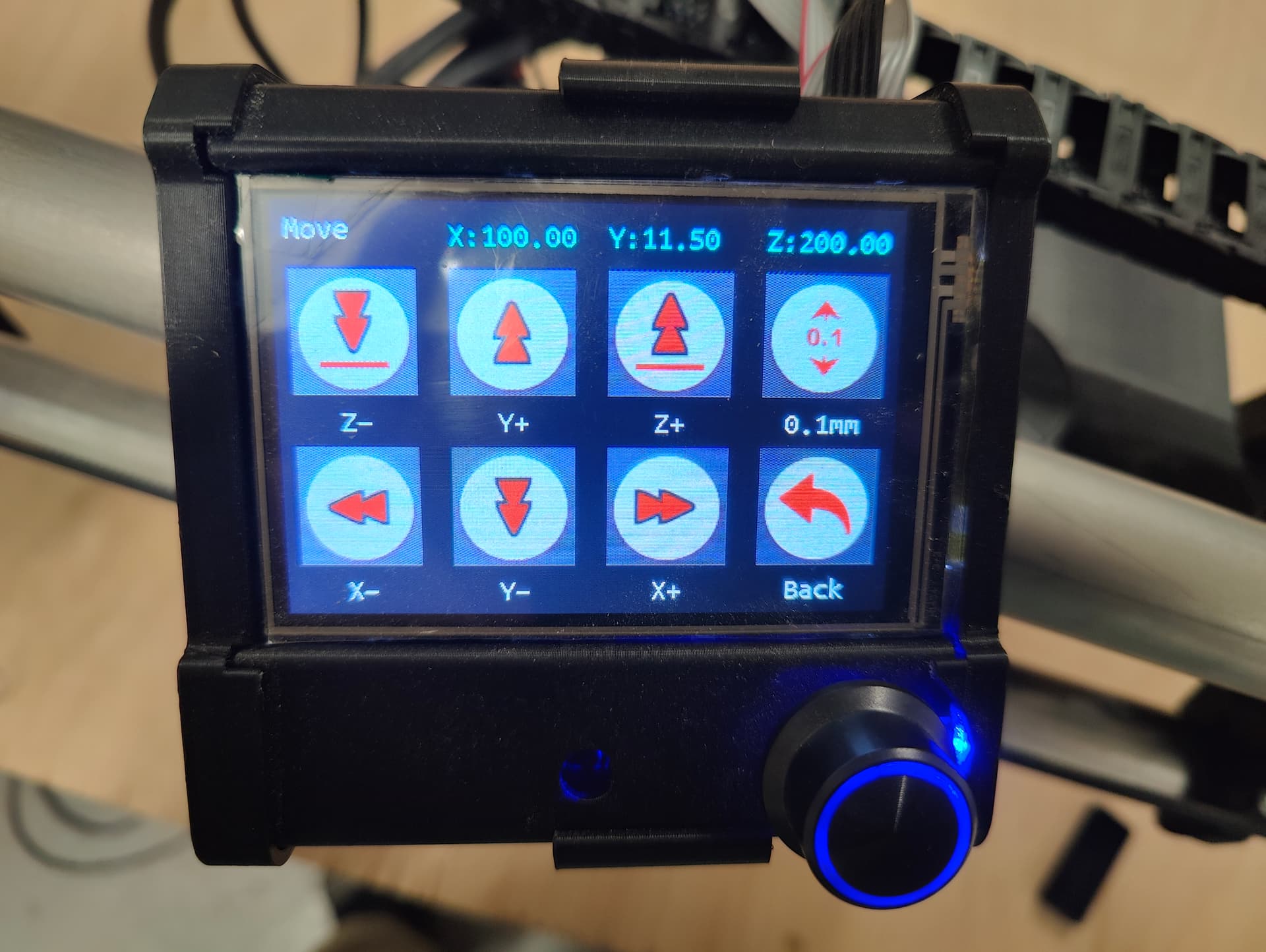
I think i’ve seen all sub-menu’s that are available during operation, but not yet have seen the coordinates.
Does anyone know if it’s possible to show the coordinates?
Also another, less important one; In the print menu, file names are cut-off at ~6 characters. More then half the screen is not used. Can I modify the number of characters that is shown from file names?

Thanks again!
I’m pretty sure that the coordinates are not shown during a print job. But to be honest, I’ve never looked.
One thing to consider is that the position of the machine could be constantly changing during a print job, sometimes hundreds of times in a few seconds. Several commands may be cached in the controller, so the position being processed by the controller may not actually be the current location of the machine.
For example, if the machine starts at X0 Y0, and a print job contains a G01 X2100 Y1400 command immediately followed by a G01 X10 Y1200 command processed, then the controller processes the first command and then assumes that the machine instantly goes to X2100 Y1400 and moves on to process the next command. The machine may think that both commands are finished, even though it has barely left the X0 Y0 starting line.
I know that doesn’t directly apply to your application, as there is a fixed location at each pause in the print job. But it may explain why the programmers never bothered to display coordinates in real time during a print job.
If you need to access the Move menu to determine the Z location, you may need to break the print job into several files, and then get the information at the end of each print job. Personally I would simply enter the commands manually on the TFT screen, but I’m old school (and old…)
It’s definitrely possible, as my LR3 with SKR Pro v1.2 displays the full file names. My Ender3 does not.
I’m pretty sure that there is a parameter in either Configuration.h or Adv_Configuration.h that will allow this, but that would require recompiling your firmware. If you are familiar and comfortable with that process, then you could go that route. I think the parameter is LONG_FILENAME_HOST_SUPPORT
You can also investigate the M20 L command and the M33 command.
Thanks for your quick reply!
Regarding the tramming: i think i will follow your advice and type in the commands one by one. It should be a limited amount of times that the tramming will be done. So a small annoyance.
Regarding the file name length: for now i have to make sure that the file name length is short and there are not to much files on the card. Maybe in the future i will try compiling a modified version. First i want the machine to be useful.
1 Like
I think that you may not understand what tramming actually is, or you are using the term incorrectly. Tramming doesn’t require you to map the Z height at different locations on your spoilboard.
Leveling the gantry does require measuring the Z height at spots near XMin and XMax. An adjustment of the Z endstops or programming a software offset is used to make sure that the gantry is level (same height above the spoilboard at each end of the gantry).
Tramming is used to ensure that the shaft of the router is perpendicular to the spoilboard. While you should ensure that the gantry is level before tramming, the tram is affected mostly by minor angular offsets in the printed core and router clamps.
The tram is checked by installing a (printed) tool with an extended arm onto the router collet nut. You then rotate the collet nut/router shaft throughout a full circle and check the distance between the arm and the spoilboard at different points along the arc. You then use a shim (masking tape) on the core or router clamps to correct the router angle
The actual Z height of the router bit is immaterial during tramming, the difference in height at points along the arc curve is what you need to measure.
1 Like
I’ve heard “tramming” to describe building a mesh for Z height, adjusting the Z endstops so the gantry is square, and for shimming the router so the bit is perpendicular to the spoil board.
Of course it is very possible that I’m using terms incorrectly. I’m still very new to this field.
In this case I’m using “tram” because the actions I’m performing are the same as described in this video; https://www.youtube.com/watch?v=NkXW_XVOLD4, where it’s called tramming.
Anyway, the goal I have is that the distance between the routerbit and the table is the same at Xmin and Xmax. And there I now run into an issue. I have don several runs of touchplate probing with the G38.2 Z0 command and I’m a bit confused regarding the corrections.
commands I’m using;
home all
G0 Y911.5 X20 (move to position at Xmin)
G38.2 Z0 F50 (probe to touchplate)
M114 (report current location & note Z-location)
Home Z
Repeat 4 times, same at Xmax at X1025 (20 mm off edge)
Calculate difference (Xmin - Xmax)
M666 Z[difference]
M500 (safe to EEPROM)
Results I got so far
| Run # | Xmin value | Xmax value |
|---|---|---|
| 1 (single measurement) | 95.2175 | 94.8150 |
| 95.2175 - 94.8150 = 0.4025 | M666 Z0.4 … M500 | |
| 2 (single measurement) | 95.3800 | 94.6575 |
| 95.38 - 94.6575 = 0.7225 | M666 Z - 0.7 (without spaces in Z) … M500 | |
| 3 (single measurement) | 96.0975 | 94.4025 |
| 96.0975 - 94.4025 = 1.695 | M666 Z1.7 | |
| 4 (avg of 5 measurements) | 95.5030 | 95.7850 |
| 95.5030 - 95.7850 = - 0.282 | M666 Z - 0.28 … M500 | |
| 5 (avg of 5 measurements) | 91.9655 | 90.8725 |
| 91.9655 - 90.8735 = - 1.092 | M666 Z - 1.09 … M500 | |
| 6 (avg of 5 measurements) | 92.6750 | 90.9885 |
| 92.6750 - 90.9885 = - 1.6865 | M666 Z -1.69 … M500 |
As you can see, I’m not getting closer to 0 difference.
2 questions;
- Should I calculate Xmin minus Xmax, or Xmax minus Xmin?
- Is there a fixed off-set I should consider in the calculations? I have read somewhere that I should subtract 0.2 from the correction, somewhere else I think 0.4.
Thanks again for your help!
1 Like
The changes are making a difference, but there are issues.
Two things you need to do.
First-lube your Z leadscrews and make sure they are moving smoothly top to bottom, no binding. Check this by moving the axis by hand.
Second-Immobilize your touchplate. If you are using the V1 touch plate tape it down. Get your hand out of the equation. The table needs to be clean and free of dust and debris, and that touch plate needs to not move. fractions of a mm are tiny.
Make sure to do your probing very slowly, the faster you do it the less accurate the numbers due to acceleration.
When you do get it close, under a half mm, please remember that this is over a full machine width. So a 0.2mm difference over 1220mm is more than good enough for most all work.
The most important part is the readings are consistent between tests when you do 5 in a row that number will be under 0.1mm difference.
Thanks for your reply.
The lead screws are lubed very well, so I expect that will not be the cause.
The advice regarding taping down the touchplate to the table is a good one. I think that was a part of the issue. After taping it down, I got better results, but still some differences within the measurements.
But I now did notice that the Z-switch blocks are not in the same place that they were before;
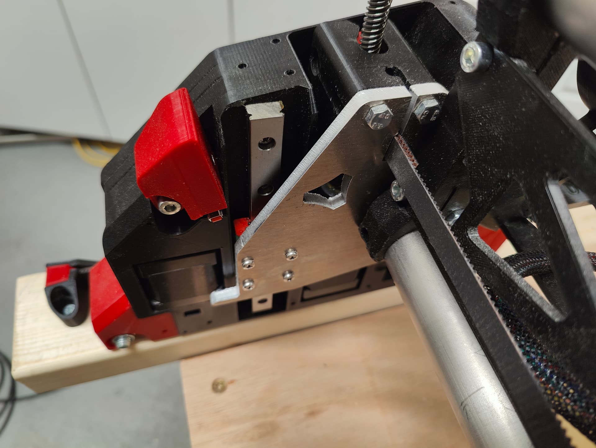
During homing to Z-stop, I noticed the red block was moving.
I have to move them down and fix them more thightly tonight and then try again. It is a balance between tightening enough and not to tight to make the printed 6-sided hole round ![]()
Definitely should be tighter. The nut should not spin. The only time they spin is the first initial threading. If you cross thread it they spin, after that you can literally crush the nut into the part. With that said, you want that part tight, but loose enough that it can move if you screw up.
Ok, so I got another brainfart. I was adding the necessary correction to the previous (cumulative). After a while, I found that the M666 command without additions, shows the actual correction. This made clear that the new correction overwrites the previous. I now got the machine very close to 0 difference (within 0,03mm between Xmin and Xmax). Good enough for me.
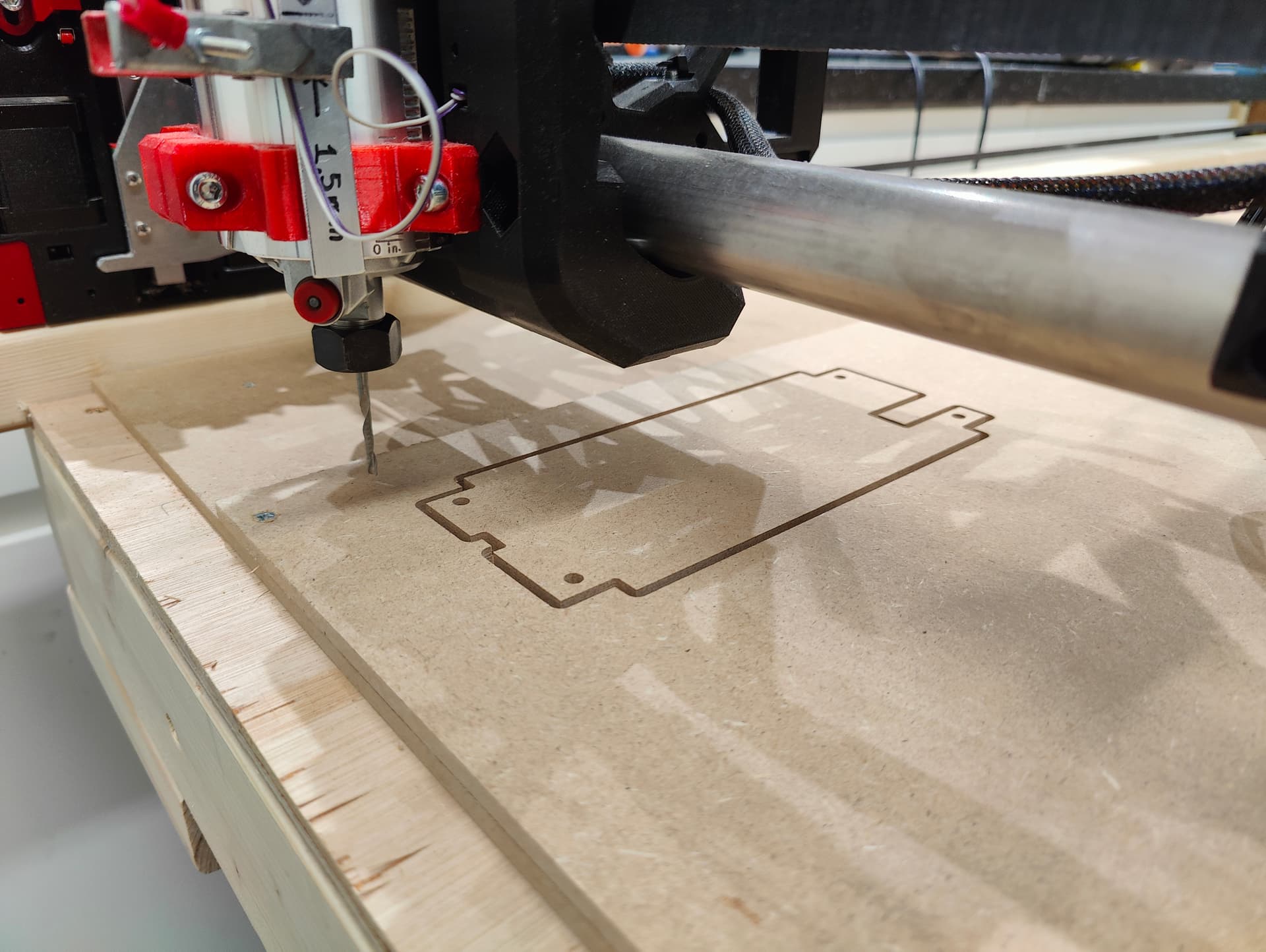
I did my first real test cut today; a very small part of the strut plate to see how it all works, and if I need to modify something in ESTLcam. I’m very happy with the result for a machine i build myself. ![]()
One new question; in 3D printing, there is a benchy test model that can be used to check for all kinds of defects in the machine. Is there something simular in CNC (aside the crown image) ?
4 Likes
Not really. You can just check the dimensions of your parts. Be warned, there are tons of way to mess up the part in CAM, and not from the machine itself. Practice practice practice and like you just did, test parts!
You are well on your way to a great machinist already!
4 Likes
Hi All,
Just an update on the progress from my side; I milled the strut plates from MDF (Whoehoe, its first real part ![]() ).
).
But when I wanted to install them, the size was off by almost 20 mm. The screw holes and bracket holes where also too small. I’m thinking of a few possible causes;
- Wrong belt type installed; checked my order; I think it was the correct one (GT2).
- Part not designed with correct size. I used this generator.
- “Something” wrongly configured in EstlCam. This last one is my first suspect
To test the first possibility, I send manual commands to move on all axis;
| X-distance send | X-distance measured |
|---|---|
| 0 | 0 |
| 500 | 500 |
| 1000 | 1000 |
X-axis; Perfect (as far as possible to measure with a tape measure).
| Y-distance send | Y-distance measured Left | Y-distance measured Right |
|---|---|---|
| 0 | 0 | 0 |
| 500 | 499 | 499 |
| 1000 | 998 | 998 |
| 1500 | 1498 | 1497 |
Y-axis; Off by 3 mm on a distance of 1500 mm. De “offset” is evenly spread over the distance (1 mm per 500 mm).
| Z-distance send | Z-distance measured Left | Z-distance measured Right |
|---|---|---|
| 200 | 0 | 0 |
| 150 | -50 | -50 |
| 100 | -100 | -100 |
Z-axis; Perfect.
While there is a small fault on the Y-axis of 3 mm over a distance of 1500 mm, this does not explain the part being 20 mm too small. It also confirms in my opinion that I installed the correct belt type.
So the treasure hunt continues ![]()
If in the meantime someone has tome tips where to look first, that would be nice ![]()
And if someone has an idea what causes the 3mm offset on the Y-axis, that would also be appreciated.
I’d be taking that out by tensioning them 3mm more, unless you think they’re already tight enough. In that case, you could adjust the steps per mm, but given that your X is good, I expect that your tension is just less on Y… +/- your measurement error.
1 Like