Hi all,
As so many others, I also was really interested in building my own CNC machine. I have seen something similar a few years ago on a RC model plane meeting and since then it kept itching.
A few years ago I started 3D printing, first with a Anet A8 and then a upgrade to a Ender 3 Pro. I really like that some idea in your head can transform into a visual in design software and it is even more satisfying when you can hold your idea physically in your hand.
In the first part of 2024, I saw a YouTube video about the lowrider v3 and was immediately hooked. I have read a lot and was in the process of ordering all parts for that. But then I noticed at the bottom of the parts list that V4 was mentioned. Then I found the forum regarding the V4 notice and it was a nerve wrecking wait with a lot of teasers on the forum .
Once that V4 was released with its build instructions, it was mentioned that first, the 3D printer should be checked for skew and dimensions. That send me trough a rollercoaster to get my stock Ender 3 Pro upgraded with Klipper, which opened the way for even more improvements. So I spend a few weeks calibrating my machine. Then the fun really could start with printing all the parts for the lowrider.
In the meantime, I spend a lot of hours on Amazon and AliExpress to get all the non-printable parts. First I meant to order everything directly from V1, but the customs fee was absolutely absurd (I think it was more then € 100 extra). The piping was purchased at a scrap metal shop.
There was even another builder in my country that offered to cut the aluminium XZ plates (@vSeccelen ; Nogmaals super bedankt !!).
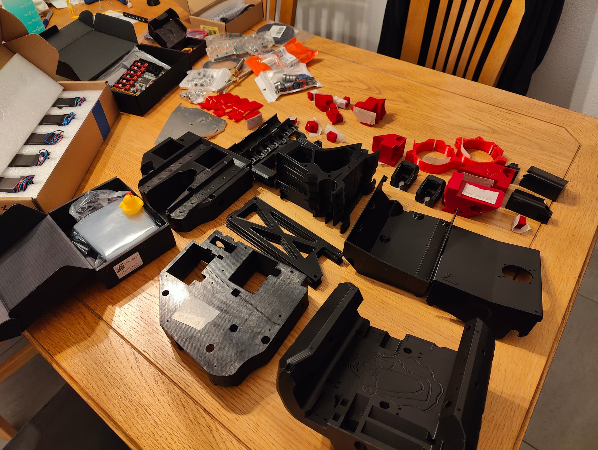
For now; some pictures of the parts that I have collected. Will upload some more posts soon.
p.s. I’m making feedback notes on the build instructions to send to Ryan as a first-time builder, maybe this can help Ryan to improve instructions for other first-timers.
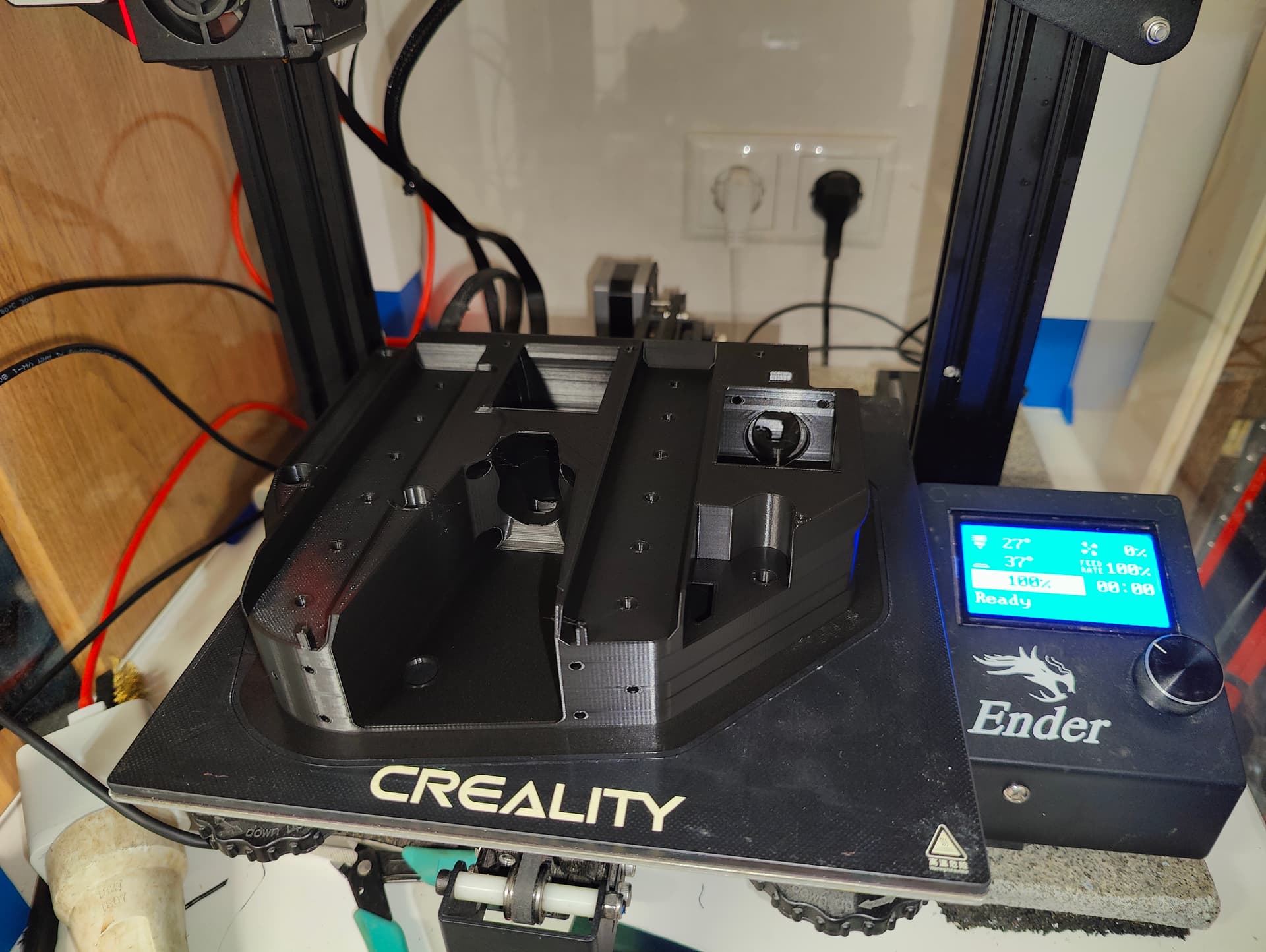
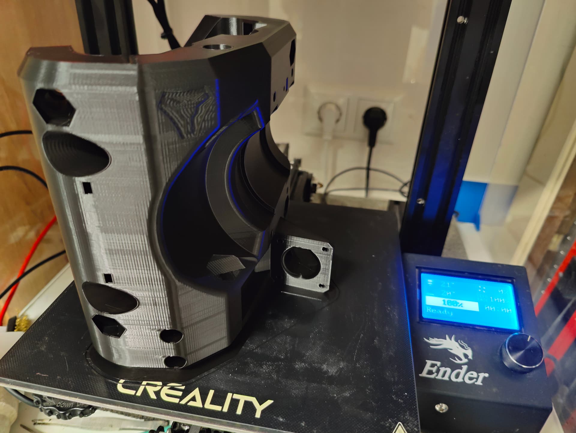
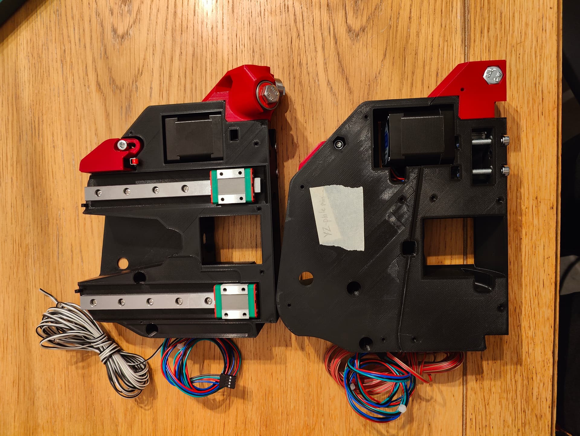
After printing all the parts (my printer never had to work that much, it is still crying ) the assembly of the side YZ blocks could start. This is a really nice activity in the evenings. All parts fit flawlessly. A lot of credits to Ryan (@vicious1 ) and the beta team for the design!
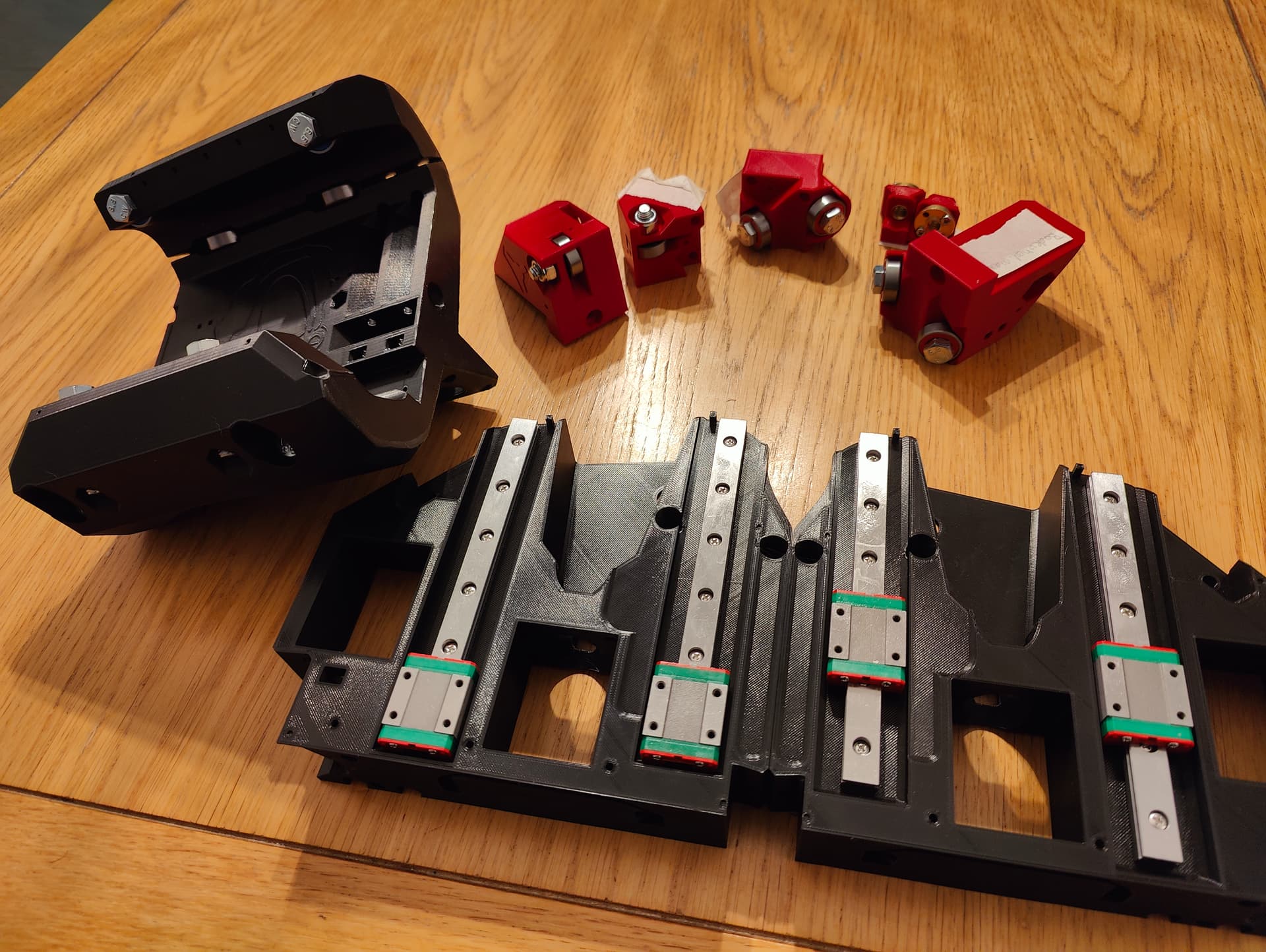
As you might notice, the bearing blocks I first installed are the wrong ones. That’s the risk of ordering parts myself instead of ordering a full kit with V1. So unfortunately there was some extra costs and some waiting time involved for the correct blocks to arrive.
Some advice for future builders; I found that it was best for all lock-nuts to first screw a screw completely in and out before installing them to loosen up the plastic part. Ryan advices to perform this action with the large nuts, but the small ones also benefit from this. The nuts that were not pre-screwed, were so tight that they damaged the printed part when tightening.
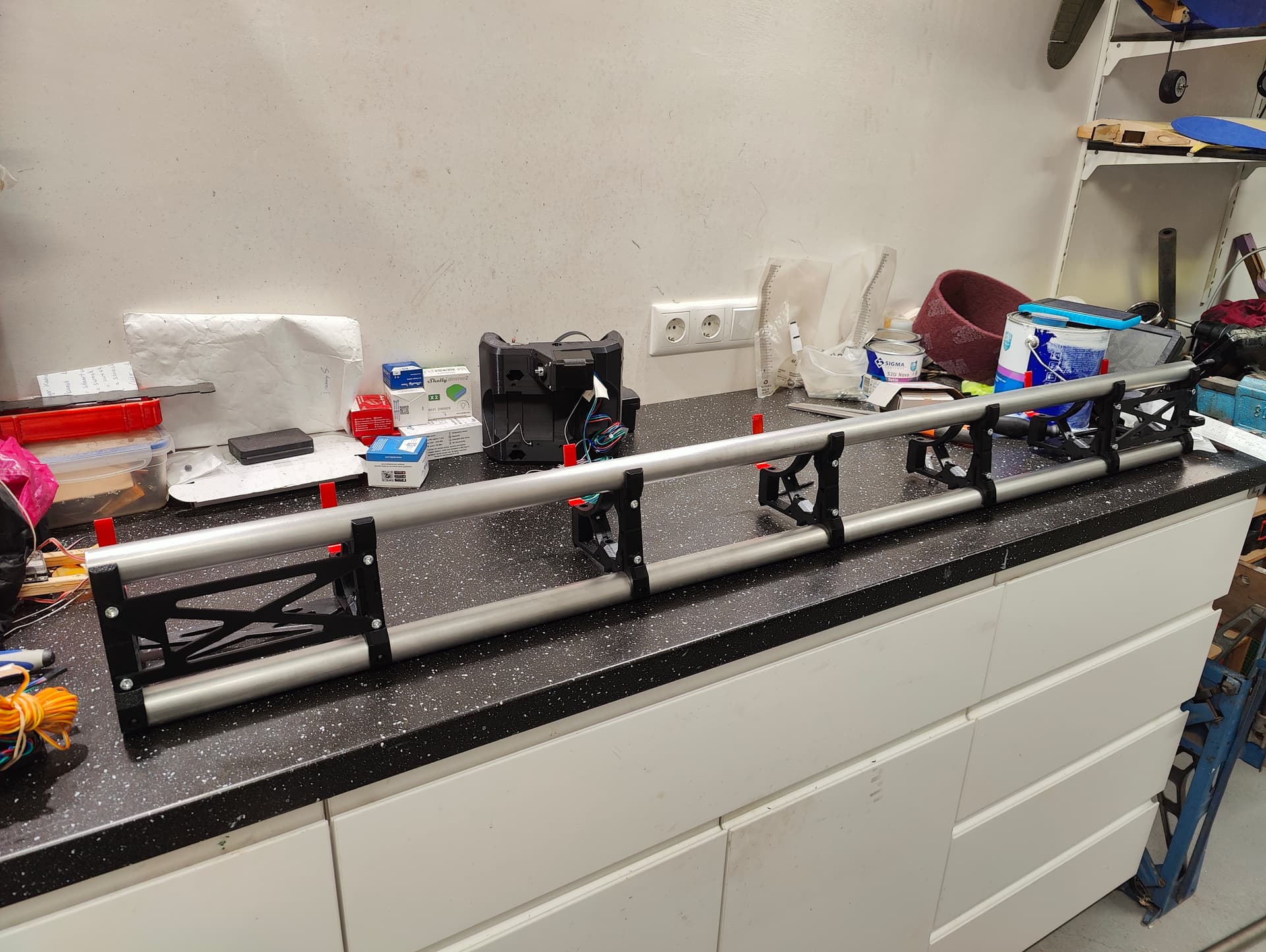
Forgot to mention this the previous post, but I’m building a size of 1830 x 1220 mm (in empirical; 6 x 4 feet). A full size machine of 8 x 4 will cause me to use a trailer each time I need a new wasteboard. At the DIY stores over here, they sell the 2440 x 1220 mm boards (full-size) and also the 1220 x 610 mm boards. I intend to use 3 of these smaller boards side by side as wasteboards. In this way, the waste boards just fit in my car and I don’t need to use the trailer. The projects I’m now foreseeing are not bigger then the 1830 mm.
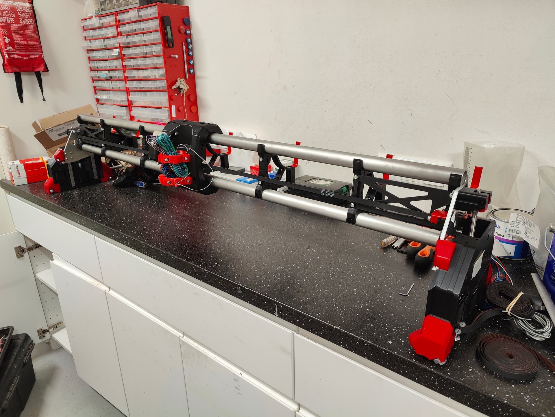
Hope you all had a nice Christmas. I used some off-time to further build the gantry. No real issues here, only tip here for others is to install the hose hooks as late as possible. I snagged my sleeve on the and broke one with that action.
The project is advancing nicely. I still have to think about how I want to build and use the table. I really like this idea;
The foldable legs and collapsible wheels make it easy for moving it around (like outside for dusty cuts) and when not in use, it can be mounted to the wall with the gantry above it to take little space in my small garage.
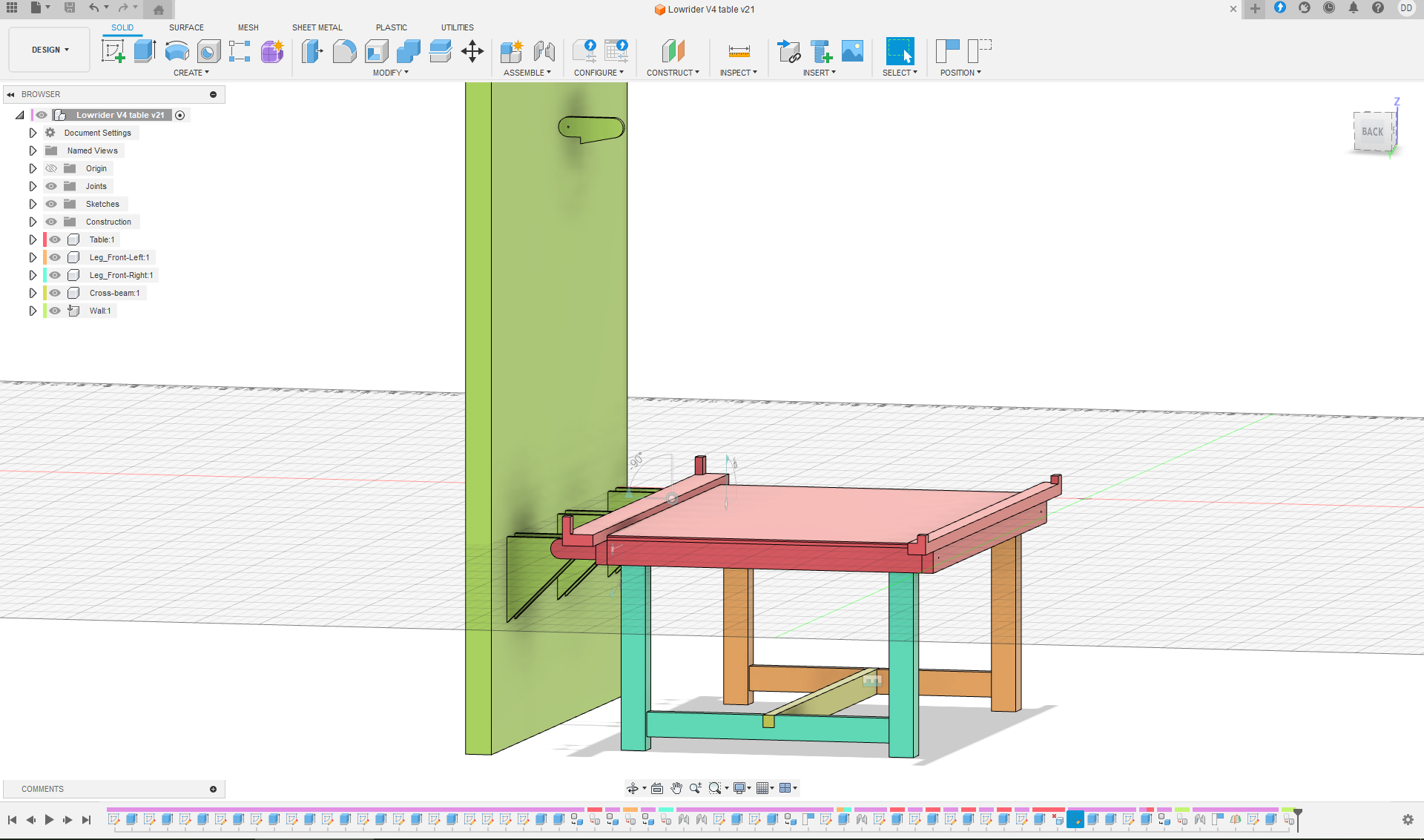
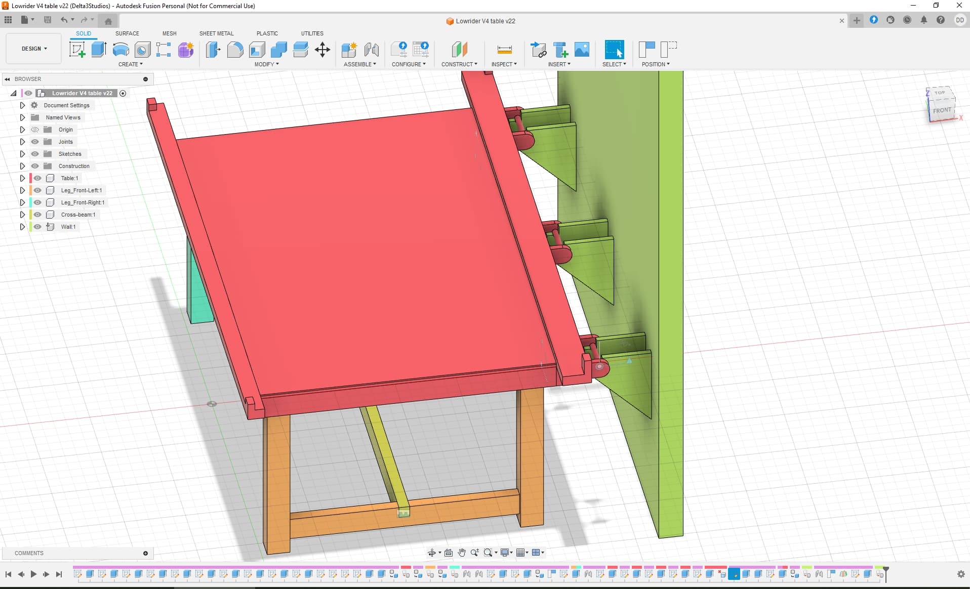
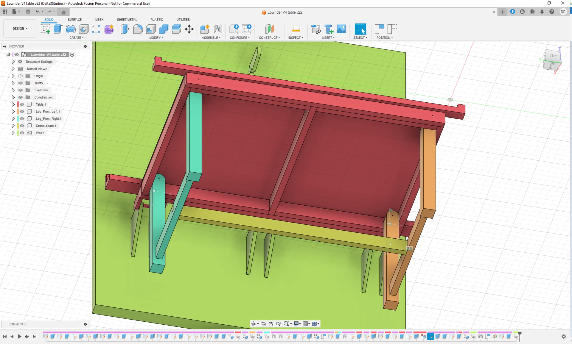
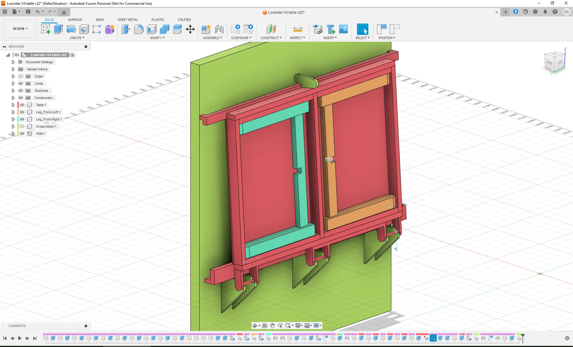
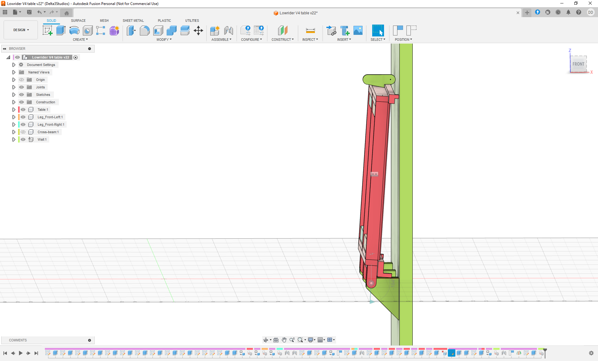
As promised, I spend some time in designing a table that is wall-mountable / stowable. Below some images. I would appreciate if someone has some feedback on this if I forgot something. Some details on the wall mounts are still missing. I will see how I mount them during construction.
And when I’m not using it, I want to be able to stow the table against the wall. The Lowrider gantry will be stored below the table on the wall (not yet put into the design).
p.s. my first design in Fusion 360, so don’t be to harsh
Thanks for this nice overview. I have looked at the designs. They are nice, but I think they all have quite a big foot. So no disregards, but I think I stay with my own design :-). I do like the idea to add a shelve below the worktable that is used on the lowrider 2 table. I have to think about if and how to implement that one.
I understand about the footprint. I like the idea of using conduit along the long edge as a pivot or hinge pin though, that’s something I’ve thought about doing if was going to make a wall mounted tilting table.
very similar to my table. I build a similar folding table to mount on wall (doubles as my table saw extension for full sheets. then I built a torsion box table top that sets on that table when using LR4. great minds…
I’m still in the progress of building the table, but it is already proving an convenient work area. Can’t wait to put the rotating wheels under it so i can move it around more easily.
I wouldn’t call myself a great mind, just lucky that i found this idea online and am able to combine it with a great machine.
Did you by any chance put some pictures of your table online? I noticed that you have posted a lot of posts, so did not yet watched them all.
Hi all,
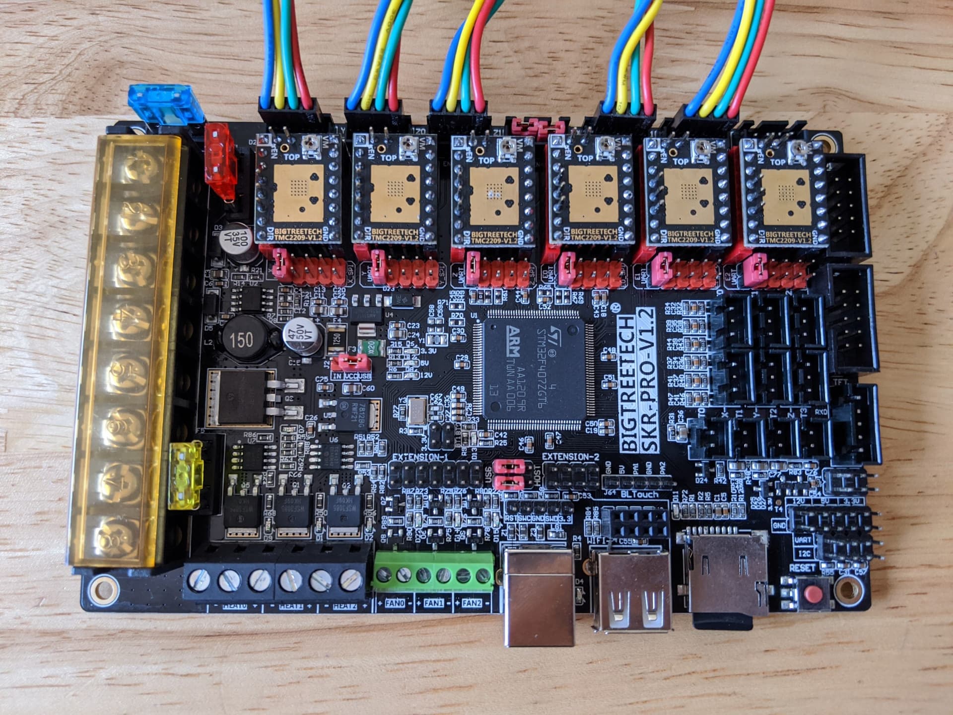
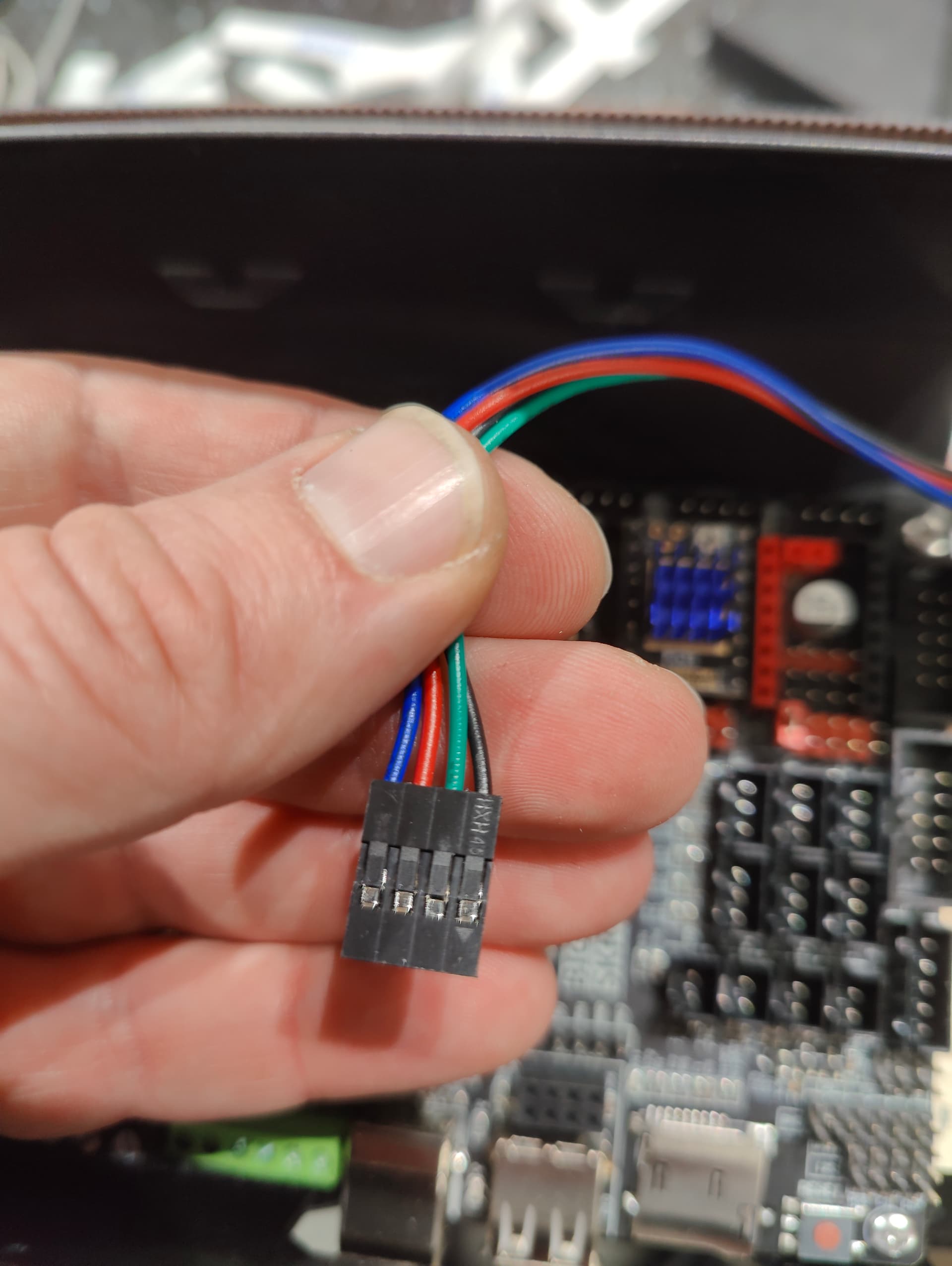
I have a question regarding stepper motor wire colors.
When I look at the images from the SKR instruction site (SKR Pro instruction), the wires have colors blue, yellow, green and red.
Is there someone that can inform me if I have to change the position of the wires? Which color should be on what position?
Can I damage the board or the stepper motor if wires are not at the correct position? I have read that if stepper motors are running the wrong way, the connector should be rotated, but if the wires are mixed up, maybe that will not help?
One additional question;
On the LowRider4 docs, positions are described as “Y-min” and “Y-max” (same for Z), on the SKR instructions, positions are described as “Y1” and “Y2” (same for Z).
Is my assumption correct that Y-min = Y1, Y-max = Y2 etc.?