DIY Coffee Roaster

There’s no harm to slowing down the motor with the motor controller, the issue is that you lose significant amounts of torque with an open-loop controller like that, it’s basically just applying less voltage to the windings. As long as the motor doesn’t stall, you’ll be fine. Given that you’ve already got a gearbox there, I’d say that’s the most logical way to address it.

I would look at putting a taller chimney on in some way, even if that’s just cardboard/wood/whatever. Having the top be open is great for getting chaff out of the coffee while it’s roasting, which a mesh lid will instead catch and potentially clog. Either way, I’d give it a try if you’ve got a sieve that’ll fit, just be wary.

Yeah, I would definitely do a few roasts by hand and get an idea of how the whole thing works out that way. I would think more agitation is probably better, to start with, so keeping that speed and keeping the beans in is where I’d be going.

At work we used to cut up heatsinks and V-slot extrusion a lot. I had a large cardboard box from something that I put over the top and cut slots just big enough to go over the V-slot extrusion once it was clamped in place and then a little hatch to reach through to operate the saw. Basically clamp it all down, put the cardboard box on top, reach through and run the saw remove the box and line up the next cut. Worked great. Slightly slower to use but so much time saved from cleaning aluminium splinters out of my hair/clothes.

An idea for added height with visibility. You can use the glass for gas lantern. My roaster uses this currently. The biggest are 5 in diameter. They also make borosilicate glass tube that would work. The flex in the sifter may be a concern attaching glass to it.

I was thinking about the chaff not lifting out & after @niget2002 comment on mesh I ordered this 11”x24” roll of stainless-steel mesh today. The flour sifter circumference is a little less than 20”, so that probably will give me a 10” vented chimney.

1 Like

This sifter outside diameter is about 6.3”. I will see if the mesh works. I am trying to keep my cost of extra stuff down to about $100. I’m at about $82 now.

1 Like

I think a mesh tube around the top is a good way of doing it. It should be quite easy to work with and Hopefully can be bent so that it just sits on top, even.

I should be able to use a hose clamp like this one to bend it to shape & then maybe not need it after getting it to shape.
RELIABILT 4-in to 6-1/2-in dia Stainless Steel Standard Pipe Clamp 121920 at Lowes.com

This design is actually coming together a lot quicker than I thought. Seems like I have only been working on the actual design of this for about a week.

I guess it is a lot more difficult to calculate the gear ratio on planetary gears. I am printing a new planetary gear with a sun gear of 10 teeth & and 3 planets with 30 teeth each which according to ChatGPT gives me a ration of 3:1. My current design has a sun of 21 teeth & 5 planets of 18 teeth and outer ring of 58 teeth which I was thinking was close to 1:1, but ChatGPT says it is a 3.76:1 which is more reduced the design with the smaller teeth for the sun. It is apparently the combined effect from rolling between the sun gear & the outer ring. Guess I did learn something today.

I found this page that will give you several teeth combinations for a target ratio based on minimum / maximum teeth counts.

Planetary Gear Generator

I did not count the teeth on the ring before as this openscad script calculates that based on the outer diameter you give it. Looks like I might have a 5:1 ratio with this new print of a sun of 10 teeth, planets of 30 teeth & ring of 50 teeth, so worthwhile printing after all.

Have you seen this:

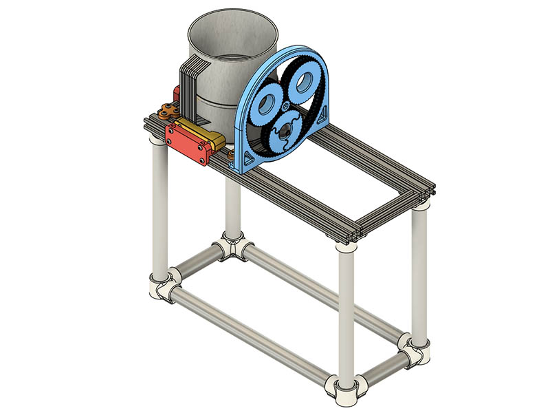
I would guess that your difficulty is that the center of rotation for the planets is fixed if you want to drive the handle directly.

So your turns ratio should be S / ( R + S) where S is the number of teeth on the sun and R is the number of teeth on the ring gear. The number of teeth on the ring gear is 2xP + S so if you want it in terms of planet teeth that would be R = 2P +S so the turns ratio is S / (2P + 2S).

The radius of your crank needs to be equal to the reference radius of your sun gear + reference radius of your planet gear. So we can say that Rsun + Rplanet = Rcrank.

The diameter of each gear is the number of teeth multiplied by the modulus, so the number of teeth on each gear is the diameter divided by the modulus. S = 2Rsun/m while the number of teeth on the planet gear is 2Rplanet/m.

Subbing that all in above gets:
2Rsun/m / (22Rplanet/m+22Rsun/m), which simplifies out to Rsun / (2Rsun + 2Rplanet). We know Rsun+Rplanet = Rcrank so that works out to the gear ratio being Rsun/2Rcrank.

So if we test that with Rcrank = 100mm, Rsun = 50mm, that would give us Rplanet = 50mm and they’d both have the same number of teeth. That would give us a ratio 1/(2+2) or 4:1, so 4 revs of the sun to 1 rev of the planet carrier, which is what it should be according to a calculator. Likewise, Rsun = 25mm gives us Rplanet = 75mm and a turns ratio of 1/(21+23) or 8:1, which also works out according to the calculator.

So you should be able to get any gear ratio you want pretty easily by varying Rsun and then defining a gear modulus to match, or by selecting Rsun such that both Rsun and Rcrank-Rsun result in integer numbers of teeth for the modulus you’re using (2Rsun/m = integer, 2(Rcrank-Rsun)/m = integer).

Working the other way, if you wanted a 10:1 ratio, you know Rsun/2Rcrank = 0.1… So if that’s a 100mm radius crank, that’s a 20mm radius sun. If you’re using module 5 gears then that’d be 2Rsun/m teeth or 8 teeth. Rplanet = Rcrank-Rsun so 80mm or 32 teeth. Rring would be 2*Rplanet+Rsun = 180mm so Nring = 72 teeth. Throwing that in to the calculator, that’s 10:1.

I started writing this before your edit with the online gear calculator, which is probably a better way to approach this, lol.

2 Likes

Thanks for the detail explanation. That helps me to understand it a little better. I know ChatGPT sometimes has errors, so it is good to have a formula to double check it. The Crank radius is 54mm. My 7-hour print came out well overnight & I put a tape marker on the sun & a planet to manually check the ratio. It came out to 6:1. Using your formula as a starting point, I worked on a 10:1 ratio. I could probably go to 10:1, but sun gear would be pretty small at 8 teeth. I asked ChatGPT for a spreadsheet formula for this and got:

A1: Center Distance (mm) → 54
A2: Ratio → 4
A3: Module → 1

A4: Sun teeth = 2A1/(A3(A2+1))
A5: Ring teeth = A4*(A2-1)
A6: Planet teeth = (A5-A4)/2

N_s = 27 teeth
N_r = 81 teeth
N_p = 27 teeth

This assumes a module of 1, but the openscad script from Gear Bearing by emmett - Thingiverse

calculates that module tooth geometry from tooth count, pressure angle, clearance, and pitch diameter which came out to 1.97mm from my variables according to ChatGPT. I modified that script some to make it simpler for me to edit.

With a sun gear of 10 teeth, 3 planets with 40 teeth and ring teeth of 92, it comes out to 10:1 with both ChatGPT & your formula, so I am printing a 10:1 planetary gear today. Tomorrow or Friday I can test all 3 ratios with the motor to see which one works best.

I added a little debossing to the one gear for it to stand out when rotating. I will have to come up with a little better graphic if I print it again.

1 Like

You could always throw a stepper motor on it and then run whatever RPM you wanted without losing torque.

That probably would have been the smart thing to do especially since I have a few laying around. Is there a simple way to run them stand alone?

I probably will use an Arduino board or something similar once I have it working, but I wanted to make it simple to start with.

I suspect you’d have needed gearing for the stepper, anyway.

There are standalone stepper controllers that would do that. I have one like this:

It works well enough. I use it for forward/reverse and variable speed for basic stuff where I’ve wanted something to just rotate.

There are also modes where you can do X rotations forward then reverse, or move forward while a trigger is held and then reverse back to the start, all which could have interesting options for other tasks.

I was looking at those sort controllers after @niget2002 mentioned using a stepper. They do look pretty handy. I will definitely have to consider one of those.

1 Like

Oh that’s neat. Never knew this exsited. this will help me greatly with other projects. Awesome!!!

I’ve run them with an ESP32 and a spare stepper driver from an old 3d printer that had replaceable drivers. I used push buttons for direction, start/stop, and speed up/down. No pictures though.

I probably have the parts to do all that but didn’t want to mess with that right now. If I had seen that stand alone stepper driver controller before I would have ordered that.

On another note, I decided to see how much it would cost for a 304 stainless steel 3d print of a simple funnel. It started out at $379 for a 90mm tall funnel 2mm thick. I got it down to $247 at 50mm tall and 1.5mm thick. So, I won’t be doing that. I used PCBway for the quote. Shapeways was over $1000, but used 316 stainless as it didn’t show 304.

I think this stainless-steel funnel will probably work. I might have to add some metal spacer on the heatgun to raise it up a little except the metal spacer would be resting on a plastic part of the heatgun & might melt it.

Amazon.com: Canning Funnel for Kitchen Use, Wide Mouth Funnel for Mason Jars, Large Canning Funnels for Filling Bottles : Home & Kitchen

The motor & controller came in today & will try that tomorrow. I was looking at the accessories that came with the heat gun & think I might not need a funnel. This will spread it out about 3”. A conical spread would probably be better, but this might work.

I don’t think a cone will actually ‘spread’ it out, anyway, as the air is leaving the nozzle with a certain velocity. You could just blank off the bottom with a bit of plate and cut a hole for the nozzle and it’ll likely to do the same thing. If you actually wanted to spread it out, I suspect you’d need to do something like the above or pass it through a diffuser anyway, which will then get f’n hot!

As long as there’s enough bean mass in the way then I think that’ll diffuse it inherently, anyway, and then as long as there’s enough agitation things should get heated evenly. I think that’s one of the advantages of the fluid bed method, it should be relatively forgiving of that kind of situation.