You haven’t even finished the plotter!!! ![]()
![]()
1 Like
I definitely wouldn’t use random aesthetic coated metal for food stuff, especially not with heat and agitation involved. Whatever that gold is, you’ll be drinking some of it.
I think anything steel will hold up to your purposes perfectly fine, it’s more whether it’ll rust if anything wears through and more than likely it’ll end up seasoning in slightly, or could somewhat easily be seasoned enough. I agree that stainless would probably be a better option. The heat you’re talking about is a couple hundred degrees, not thousands, though, so I’d have no issue with steel or even aluminium. Zero chance you damage aluminium with a heat gun ![]()
I would say do a few roasts with the setup before trying to modify it and get a feel for what’s important. Do the bare minimum to make it usable and then go from there… Fluid bed roasters are kinda finnicky anyway, so I don’t know that I’d put a ton of effort trying to make one super nice before getting a feel for how consistent it is, first.
The flour sifter I have is listed as stainless steel, so it should be. I’m going to get this setup enough to test it without putting any bells & whistles in it. I just have to build a simple stand & clamp it down. I will probably hand crank it for the 1st batch test. Think I do want to use a motor of some sort to drive it eventually rather than a drill as that would give a more consistent movement & be easier to deal with. Anyone have suggestions for what type of motor to use with this?
I took that design as far as I could and put it aside since I could never get the accuracy I wanted.
1 Like
If you’re going to use a drive motor eventually, I’d be focusing on whatever makes that easier instead of driving the handle, unless you want the backup capability of pulling it off and manually turning the handle. In that case, a 2nd sifter might be worth the investment! ![]()
I think my approach would be to bend the handle out straight, cut it off and then stick a shaft coupler on it. A piece of plywood or whatever with a hole for the handle, band clamps around the body of the sifter to the piece of wood, mount a 30-60rpm gearmotor via the shaft coupler on the far side of the piece of wood. I’d probably file some flats onto the shaft as well, as much as possible.
Without having used one, I’m not sure how much force I’d be expecting in terms of keeping everything moving, so this is done under the assumption that it’ll be low enough force that there’s not much resistance when using the knob.
If I were trying to cobble this together now, I’d probably sacrifice an old battery drill (I’ve got a couple of 12V Bosch ones lying around from previous use but they can be found cheaply on FB marketplace or whatever) and just tighten the chuck directly onto the straightened shaft. For speed control you can just use the trigger and cable ties to get it ‘about right’, I’ve done that plenty of times for makeshift setups and it works ok. Just clipping the battery in and out would give control to start with, although newer drills may not start in that case. Alternatively you can open the drill, make a hole in the case to pull the wires for the motor out and hook them up to a cheap AliExpress motor controller powered by a 12V wall wart. I’ve done that a few times for makeshift rotary devices like making a tumbler, rotisserie, makeshift live-tool lathe, that kinda thing.
Dunno if any of that helps, just some random thoughts about how I’d approach it.
If you do want to stick with the unmodified sifter, I’d maybe try print something that clips/hot glues onto the bent part of the arm rather than driving the knob directly. That seems easier, to me at least. If you want some inspiration for an easy way to drive that, I’ve had good luck using hex bolts through a hole and printing a close fitting hex cavity for the head to stick in. Or even the same approach with a nut on a machine screw and then a jam nut to stop it turning.

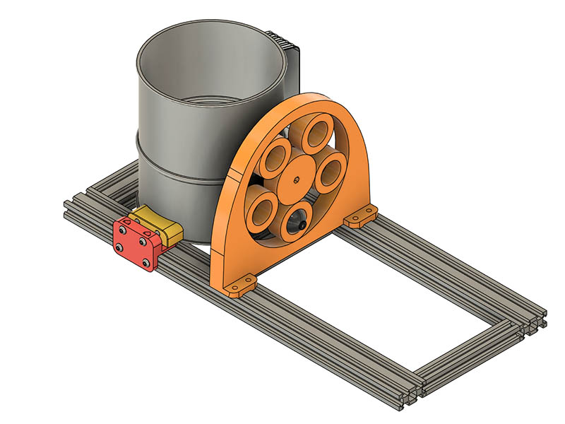
I found a couple of little motors in my supplies to try when I get to that point. I will consider straightening the shaft plan B. I think the planetary gear system gives the design a little more character. I designed the clamping system for the sifter today, using a CNC clamping design as a starting point. I show this photo with 2 clamps but could add a 3rd if that is not enough. I will 1st test it with 2 and also to see if it gets too hot for the plastic. I could print the push clamp part in ABS to give it a little hotter tolerance.
3 Likes
Right, I follow you.
A sheet of aluminium foil over some cardboard works well as a radiant heat barrier and insulator if you do need to keep the plastic cooler. I’d guess you might end up with a fair bit of radiant heat coming off it.
Thanks for the tip. That might be all I need. I have the top frame all together but used 3d printed V-slot 1040x140mm lengths for the cross ties until I am sure that is the size I want before cutting the extrusions. I am sure I could not get away with plastic ones there. I have been researching looking for a stainless-steel funnel to put over the top of the heat gun to spread the flame evenly. i found some that might work that are used for filling mason jars, but they are about 2” or so at the small end. About 1.5” would be better. That actually might be a good use case to get 3d printed out of stainless steel since it does not use a lot of material. I didn’t price it yet though.
Think I have this modified planetary gear with support ready to print & plan to print it tonight since it looks like a 7-hour print at 20mm thick.
You can get thin stainless steel sheet that you could always fold into a funnel shape. If there’s a funnel that comes to more of a point, like one for filling bottles instead of jars, you could cut the tip off to the right shape for the nozzle to go in.
Given that it’s not going to be in contact with the beans, anything that’ll hold up to the heat without doing anything nasty could be used, as well. Wrapping some aluminium shim stock or something around the nozzle to pack it out to fit in the 2" opening, perhaps?
The 7-hour planetary gear print came out well & fits like a glove. I also change the 4 brackets holding the 2040 cross ties to the long 2040 sides. They were pulling apart when I tightened the flour sifter clamps. I also added another flour sifter clamp on the end & widened the one on the flour sifter handle side & cut a little gap in that one. This planetary gear system seems to work quite well now even at very high speeds. Here is a video of the 2nd test.

3 Likes
I’m looking into motors now. I was looking at the motors used on filament winders and they seem to use the jgy370 motors which is a similar torque that I need. Now I need to decide on what RPM to use. Seems like 1 - 2 rpm per second would be sufficient & that would be a 60 - 120rpm per minute. Seems like I saw somewhere that you shouldn’t go +/- 20% the rated speed of these motors. Does that sound right?
I decided to order a 150rpm from Amazon since it was hardly any difference in price with alliexpress.
Here is the one I ordered.
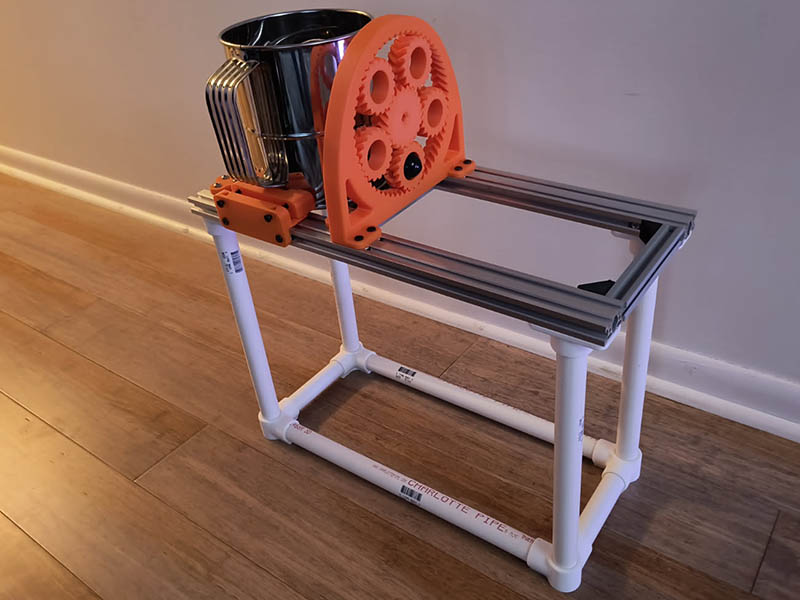
I was in my shed today & realized I had a lot of PVC around from another project & decided to see if it would work for a stand. After trying the drill test again, it seems sturdy enough and should be far enough away from heat. Now that I have a stand, I can try some heat tests to see if the plastic clamps are affected.
I looked at some ductwork at Lowe’s today to see if that would work for a heat funnel. I am not sure that is a good material to use though.
2 Likes
Ductwork would be galvanized steel. But I don’t think you’re talking hot enough for the galvanized materials to be an issue. I only know it’s bad if you’re welding it. Claude says galvanized steel becomes hazardous above 500F when the zinc starts to off-gas. So maybe you’re getting closer than I thought.
Does the heat need to be diffused? I would think just mounting the heat gun under the sifter and pointed up into the base should be good enough.
It would probably get close to that temperature. Google search shows 2nd crack between 438 to 450F (225-230C). The heat from the heat gun will probably getting hotter than that.
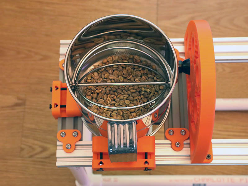
I might also have to modify that flour sifter after all. I put 6 oz of green coffee beans in there this morning to see how well they turned. I really should have done that 1st thing into the design. Turning it too fast will definitely throw some beans out which I sort of expected. Even turning slowly, the agitator catches the beans sometimes and they go flying. If I can get the agitator bent just a little bit so it doesn’t actually scrape the bottom screen it would probably work better. I needed a flour sifter with this defect. The crank shaft going straight through is 5mm with a 5mm nut holding it on. The internal agitator is attached somehow to that shaft and will not slide out. I really don’t want to give up the planetary gear. I am rotating the planetary gear 180 degrees & changing the mid V-Slot brackets to allow for it. Think I need to do that to have room to put the motor mount on.
Here is a photo of the inside of the flour sifter with 6 oz of green beans. That is about 3x the amount I can roast at a time with the popcorn popper.
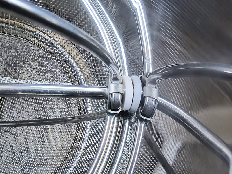
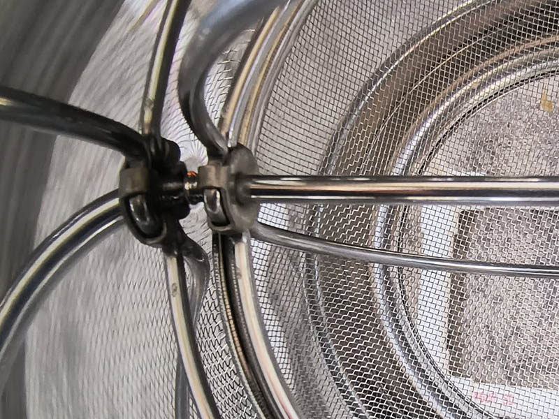
Here are a couple of photos showing the inside connections of the agitator.
I’d just put a mesh lid on top to keep the beans inside and let them bounce around.
1 Like
Thanks, that might be the perfect idea. While walking today, I was thinking that 150rpm motor might be way too fast since this agitator hits the beans 4 times per revolution. How much slower can you run those motors with the speed control without harming the motor? I was trying to think of some type of lid to use but wanted to be able to see the beans. I had forgotten about this video where a guy did something similar to that on a popcorn popper.

I just got some of these 2-3 rpm motors to try for a curing chamber. I’m not sure if they would work for this as well. They also are available in higher RPM ranges.
Can’t you just re-design your planetary gear for a slower turn?
That’s not a bad idea and think it will work. You have all the answers for me today. Looks like I can do a sun gear with 10T & 3 planets of 30T which will only increase the outer diameter to 210mm from 178mm which is doable. According to ChatGPT that gives me a 4:1 Gear Ratio. I think that 150rpm motor I ordered would put the speed of the crank at 37.5rpm with no adjustment of speed. That might be a good speed.
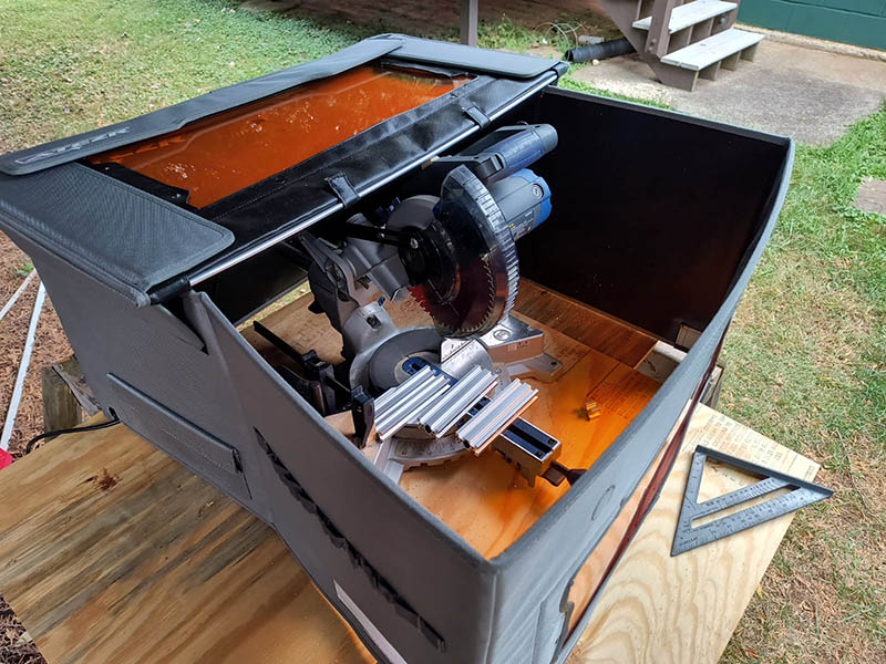
I finally cut the 140mm lengths V-slot today. I have a Kobalt 7 1/4 miter saw I use, but it always messy. Today I decided to use the cover on my laser engraver to keep all the metal in one place & it worked quite well.