And good! I would MUCH rather see this! I honestly have no desire to cut and sell aluminum plates. But it was mentioned offline and if someone REALLY wanted it but didnt want to do it them selves then I would entertain it! I would much rather just stick to doing the custom laser work on the wood struts ![]()
1 Like
I propose a “twist test”.
Hypothesis: securing the braces and/or strut to the X tubes will produce a resistance to twisting forces in the gantry beam. Additionally reinforcement of the strut to tube should serve to reduce deflection of the beam in Z, though given that the horizontal strut cannot be connected to the tube, no additional resistance to deflection on the Y axis should be expected.
Methodology:
By lifting the toe of the XMin side YZ plate with the core at a preset position, and Y also consistent, or Y belts disconnected, we should be able to measure a difference in the amount of lift between a non-reinforced, and a reinforced gantry on the same machine at the X Max side. Ideally, any lift of the toe at X Min will produce a comesurate lift at X Max.
Corroborating evidence: currently, on my 32" beam, I am able to lift the X Min side toe by several centimeters before the X Max toe lifts from the rail. I have not yet reinforced my gantry.
My proposed reinforcement will be use of silicone caulking between the face strut plate and the X rail tubes, on the theory that the weaker link (compared to screws in the braces) over a larger area will produce equal or greater reinforcement, and have the ability to be removed if this introduces an unwanted twist in the beam. This also allows a further reinforcement of the screws later if further reinforcement is desired.
My expectation is a significant reduction in the amount of twist that the weight of the beam will naturally allow.
Alternate testing: Since Doug has managed to insert screws onto his X rails, he can perform this test in the “after” state as-is. I would suggest that removal of the screws would be very nearly the “before” state, and would validate, but not quantify any increase in twist rejection, since additional friction as the holes in the tubes reach the edges of corresponding holes in the braces is to be expected.
6 Likes
Am intentionally cutting Struts with wings with small gap near the Pipes for this reason. Planning to use epoxy or something that can reliably bond to braces and final Strut materials (JB Weld or something AI suggests).
IF, fastening braces to pipe is demonstrated to be helpful, then maybe… Just fastening the end braces, but not all braces would be good enough to help with twist rejection. Just fastening the end braces would be easier to not mess up than trying to perfectly align all the braces, maybe using slightly undersized #6 self taps would help. Maybe this, maybe that… I should to go cut stuff, and closely observe what the machine actually does.
1 Like
I’m currently remaking my touch plate probe wire, as per shown in the Printables listing and video below. My reason for remaking it, is the first time I made it wire that was too heavy gauge, and it did not matter then because on LR3 I was not routing it through wire management tunnels like on the LR4. So, now I need the wire to be closer to the recommended gauge.
Thinner wire: check.
Crimp on connector for stainless steel: check.
Crimp on Dupont connector to the Jackpot: check.
Disk magnets: check.
Super fast prints for parts: check.

3 Likes
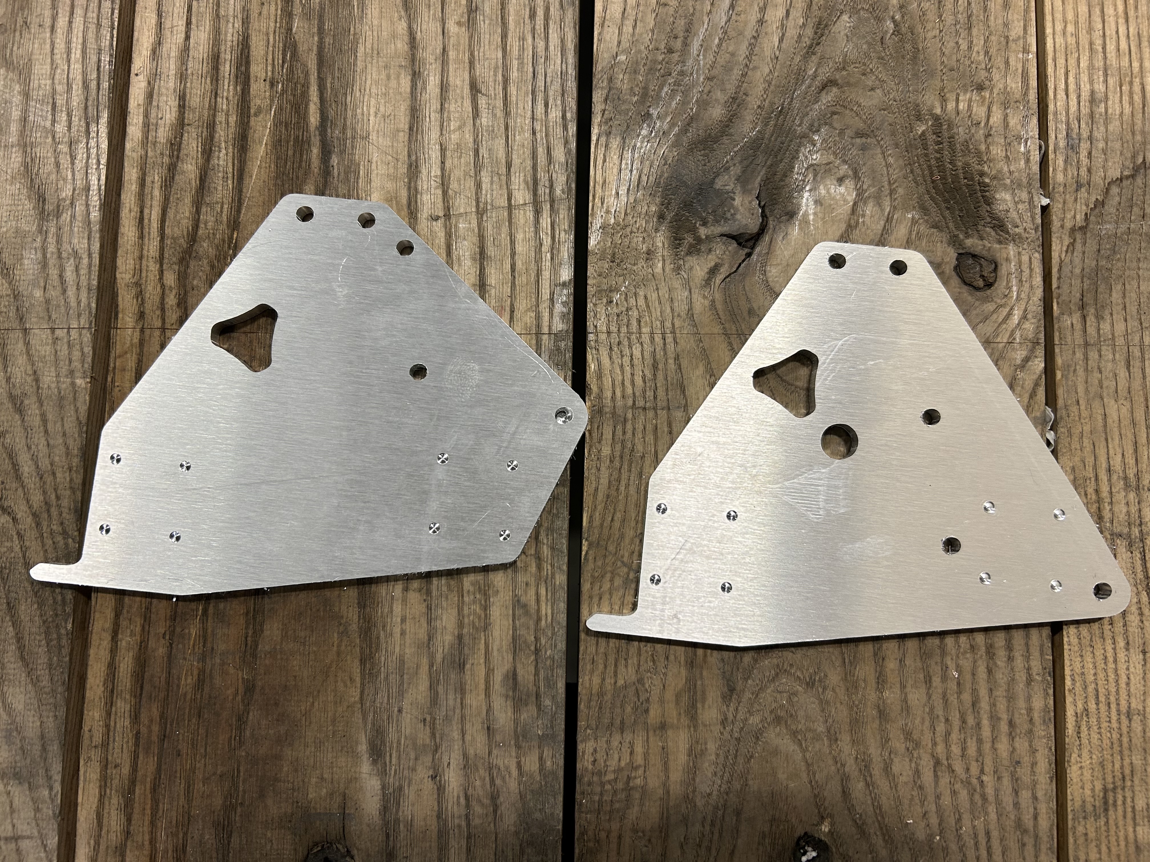
Thanks for your aluminum milling vid Doug! I was able to get these cut today using the speeds and feeds suggested in your video. Almost have all the printed parts done as well so it’ll be time to cannibalize the ol’ V3 before too long.
6 Likes
That is so cool that you were able to do that! I’m still so thoroughly impressed and pleased that both the LowRider 3 and LowRider 4 can do these kind of aluminum cuts. I just cut some more 1/4” thick aluminum today using my small RC3 LowRider 4 build.
2 Likes
I got the following completed:
- side assemblies
- core
- gantry
- assembly of all above main components
- belt tensioners & belts
Next up: running wires, testing motion, & running dust collection hoses, etc. Whew! ![]()
3 Likes
@DougJoseph, I appreciate all the mods you create and share.
No pressure, but I am selfishly curious if/where a LR4 update to your LR3 Kinematic tool less quick change accessory holder ranks on your todo list. Maybe @jamiek or someone else has already look into this? Am happy to have a go, but I don’t want to duplicate other people’s efforts (especially when they’re more proficient than me). Cheers!
1 Like
I will try to work on that either tonight or tomorrow! ![]()
My thinking is to use Jamie’s improved version of mine, but adapt it for LR4 if possible.
4 Likes
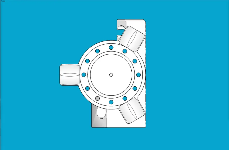
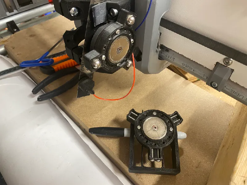
OK, @azab2c —
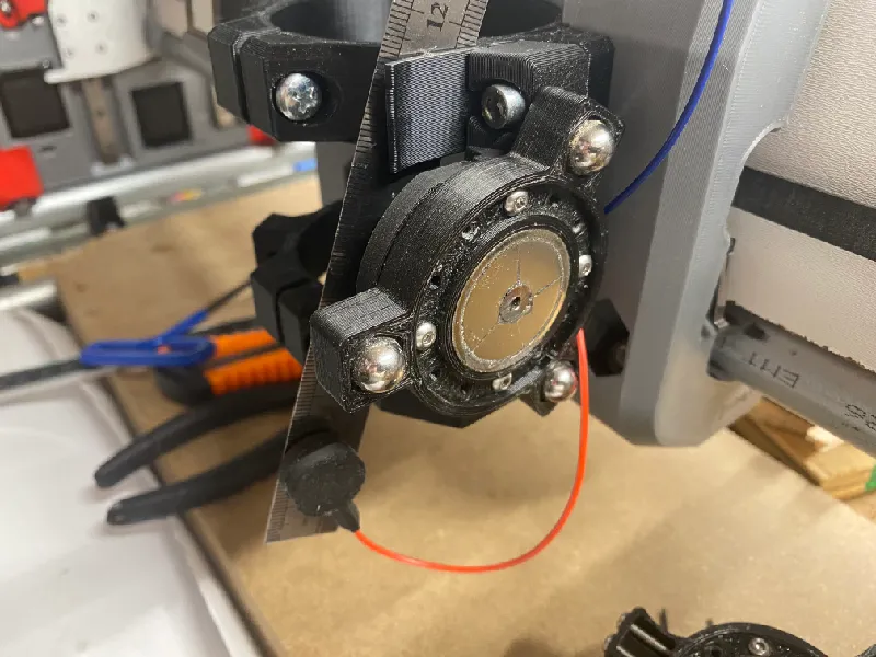
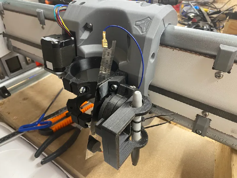
I got a new “Main Mount” designed, printed, and installed on my LowRider v4, that allows my Kinematic Accessory Tool holder from before, to be attached and used with LR4!
The following is copied and pasted from the Description:
This allows use of my earlier kinematic accessory tool mount on the awesome new LowRider v4 CNC.
Here’s an old-yet-helpful video I made about the earlier version (which was for LowRider v3):

This whole deal is an adaptation of a Maxwell Kinematic coupling. You can read about that here: Kinematic coupling - Wikipedia
Original motivation was a nudge from Jamie K on the V1 Engineering forum.
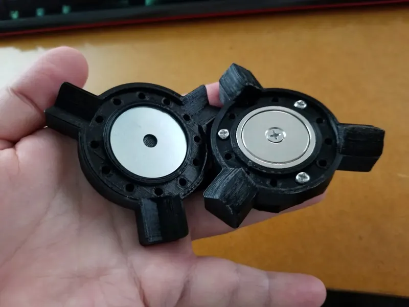
Speaking of which, Jamie has now remixed this in a way that requires no acorn nuts, no screws for troughs, only one magnet on one side, no need for drilling any magnets for additional countersinking, and no need for prying any magnets out for flipping them. Check out his remix here. His remix avoids acorn nuts and avoids troughs made from screws, all by having both “mounds” and “valleys” made from 3D printed plastic. Here’s a photo of Jamie’s remix:
What’s new?
The previous version was designed for LowRider v3. This new “Main Mount” enables use on LR4. Since the only part that needed modified was the “Part A, Main Mount,” only the new version of that part is provided here. For the other parts, you can download and use those from either…
… Jamie’s excellent remix that requires less hardware:
…or my earlier listing:
Also, this is backwards compatible, so if you already made a set for your LR3, you can use all of it except the main mount, on an LR4.
Caveat:
- Depending on the size and shape of whatever tool you attach, you should double check your range of X axis travel, as your tool’s shape may result in a reduction of X axis travel, in order to avoid a collision at the X max side.
Notes:
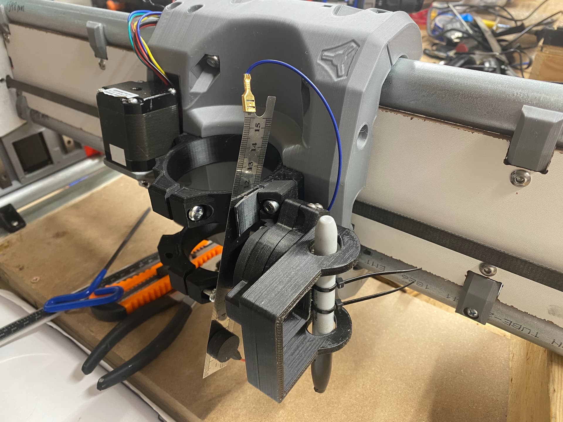
- I designed a narrow slot in this new “Main Mount” that is intended to allow a Tiny Touch Plate (from Ryan’s store) to be stored in the holder clip that he designed on the upper tool mount. If this prints well, and works, great. If not, then my own touch plate (which is wider than Ryan’s) does indeed store well in the upper mount clip, as it then “leans” its edge against the lower tool mount, out in front of it.
- I changed the previous targeted angle of the mounted “Fixed Base” part from this:
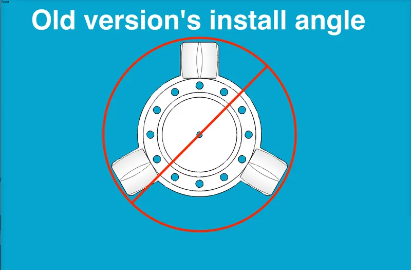
… to this new angle for LR4:
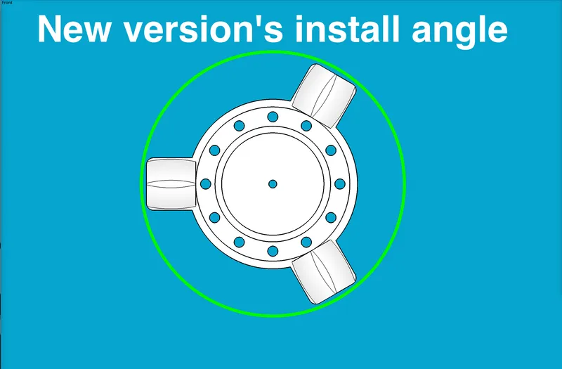
…which, when attached to the main mount, looks something like this:
…where the LR4 core would be just to the right of this side view. The reason for this change was to minimize the offset distance away from the gantry, in order to help strengthen the mount’s rigidity.
Speaking of which, this mount does seem more rigid than the previous version, owing in part (I think) to the fact that it’s attached at three points instead of two in the previous version. The three points of attachment to the existing LR4 core’s tool mounts are revealed in the simple directions for…
Assembly and Installation
- Print all parts and install all magnets / washers as desired. See links below.
- Using M3 x 16mm screws and M3 nuts, attach your desired tool holder(s) to one or more “Mobile Base” part(s). There are capture slots for the nuts.
- Using M3 x 16mm screws and M3 nuts, attach the “Fixed Base” part to the “Main Mount.” There are capture slots for the nuts.
- To install the combined assembly of Fixed Base and Main Mount to the LR4 core:
- On the top and bottom tool mounts, on the right side of each, remove the two M5 x 30 mm screws,
- Place the “Main Mount” part in position. (Mine snapped in with an audible click.)
- Replace the two original screws with M5 x 45 mm screws. (That makes two of the three points of attachment.)
- Install an M5 x 30 mm screw vertically down through the spare auxiliary mount hole on right side of the bottom tool mount. Use an M5 nut on the underside. There is no capture slot for this. (That makes the third point of attachment.)
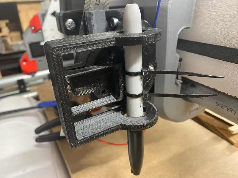
- Magnetically click a “Mobile Base” toolholder onto the “Fixed Base.”
- Done!
Hardware / BOM:
- Filament of your choice (I’m using PLA)
- These disk magnets: Amazon.com
- Two M5 x 45 mm screws (from my stash but like these): Amazon.com
- 12 or more M3 x 16mm screws & nuts from this assortment: Amazon.com
- Some washers that are about 1.25" in diameter. Be sure to get steel washers that are subject to magnetic attraction. (Not all are! I think if it says “galvanized” then it is.)
If you are using my earlier design parts that require more hardware,
- Two M4 x 10mm / 12mm screws & nuts from this assortment: Amazon.com
- Three (3) of these ¼"-20 acorn nuts: https://www.lowes.com/pd/Hillman-3-Count-1-4-in-Nickel-Standard-SAE-Cap-Nuts/3035978 (Or if you want to have a stash: Amazon.com - but see the note on earlier Printables listing about the differences between brands. The Amazon listing is the one that is about 2.7mm taller than the Hillman brand from Lowe’s.)
COMPATIBLE TOOL HOLDERS:
- Air Mist Mixer Mount: LowRider 3 CNC - Add-on - KINEMATIC Air Mist Mount for Tool-less Quick-Change Accessory Holder by Doug Joseph (design8studio) | Download free STL model | Printables.com
- Pen Holder Inverted, remix of Jamie’s inverted pen holder: LowRider 3 CNC - Add-on - KINEMATIC Pen Holder - designed for LR3 Dust Shoe (v4.1) by Doug Joseph (design8studio) | Download free STL model | Printables.com
- Laser mount for NEJE A40640 Diode Laser: LowRider 3 CNC - Add-on - KINEMATIC Laser mount v4.1 - designed for NEJE A40640 on LR3 Dust Shoe (v4.1) by Doug Joseph (design8studio) | Download free STL model | Printables.com
- Pen Holder, not inverted, v4.0 - generic design for pens on LR3 Dust Shoe, made for this v4.0 kinematic system: LowRider 3 CNC - Add-on - KINEMATIC Pen Holder v4.0 - generic design for pens on LR3 Dust Shoe (v4.0) by Doug Joseph (design8studio) | Download free STL model | Printables.com
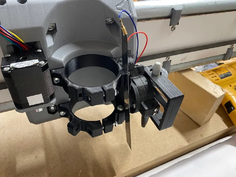
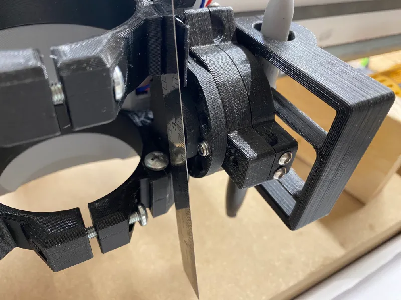
- Drag Knife Holder v4.0 - 1.0mm spring leaf (for drag knife such as sold by V1 Engineering): LowRider 3 CNC - Add-on - KINEMATIC Drag Knife Holder v4.0 - 1.0mm spring leaf (for drag knife such as sold by V1 Engineering) by Doug Joseph (design8studio) | Download free STL model | Printables.com
Printing tips
- Print as oriented.
- Suggested layer height with a 0.4mm nozzle: 0.28mm — I tried printing with a thinner layer height, but then the bridging (over the slot for the Tiny Touch Plate) did not do as well.
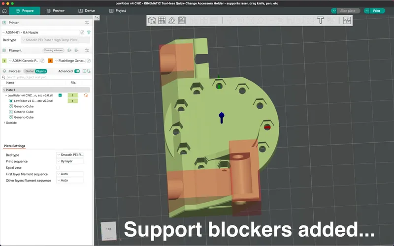
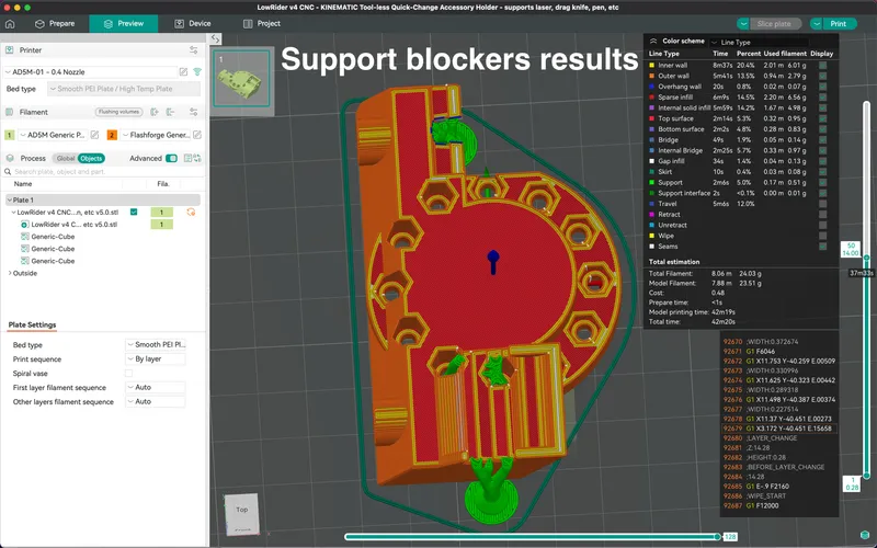
- Supports are encouraged. I regret this, but because of the slot intended to accommodate the Tiny Touch Plate, the design is complicated just enough that supports seem called for. I switched on Tree Supports, checked the preview, and added some support blockers to reign in the madness. See pics below. The one support blocker shown in the lower left forced bridging over the slot, as opposed to having a tiny slot full of support material.
A full “clock face” of nut capture slots on back:
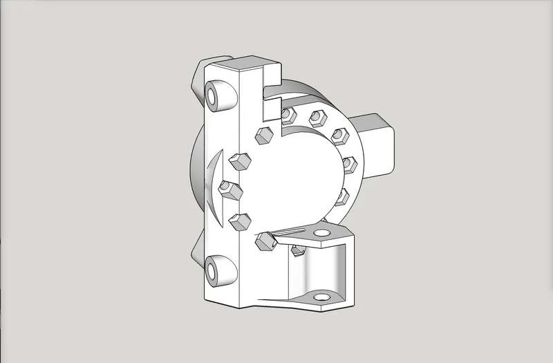
Backwards compatible - my old parts shown attached here:
Change log:
- October 24, 2024 — initial release posted. Consider this as “in beta.”
My PayPal tip jar: https://paypal.me/design8studio
Various LowRider 3 CNC remixes:
View all my models and remixes on Printables:
*Amazon product links are affiliate links.
4 Likes
Doesn’t this cause a problem for all of the accessories? Especially for Jamie’s version?
Won’t the Laser mounts, pencil holders, etc all need to be redesigned so they aren’t turned away from the spoilboard?
Forgive me if I’m missing something, I haven’t actually used any of them, just the first thing I thought while reading this.
1 Like
oh… is it because of the mount nuts can be used to attach differently? Is your offset aligned with the nut hole increment??
2 Likes
I don’t think so.
There is a full clock face of screw holes, so the intermediate part, the Mobile Base, could be rotated, without the tool holder itself being rotated.
Some things may need redesigned, but I think most will be OK.
1 Like
yes. This!
1 Like
The “cover” image of the listing, shows my previous pen holder attached for use. All I had to do was change which of the screw holes were used for attaching it.

1 Like
yep, I see. Your holes still align on the vertical…so should be fine…
2 Likes
NOTE: I just now posted a minor revision to the Printables listing.
Change log:
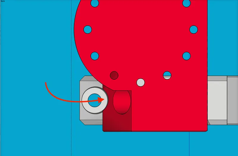
- October 24, 2024, ~8:30pm — Re-uploaded because a tool access notch was on the wrong face. Corrected it. The notch allows screw to be inserted in the lower tool mount’s tensioner adjustment screw hole. The corrected notch is shown here:
1 Like
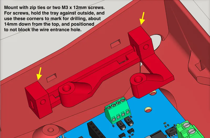
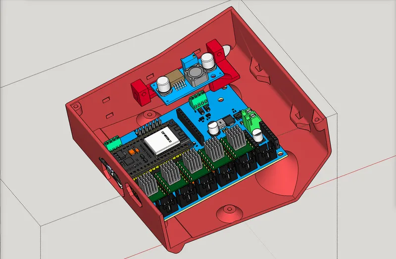
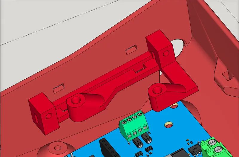
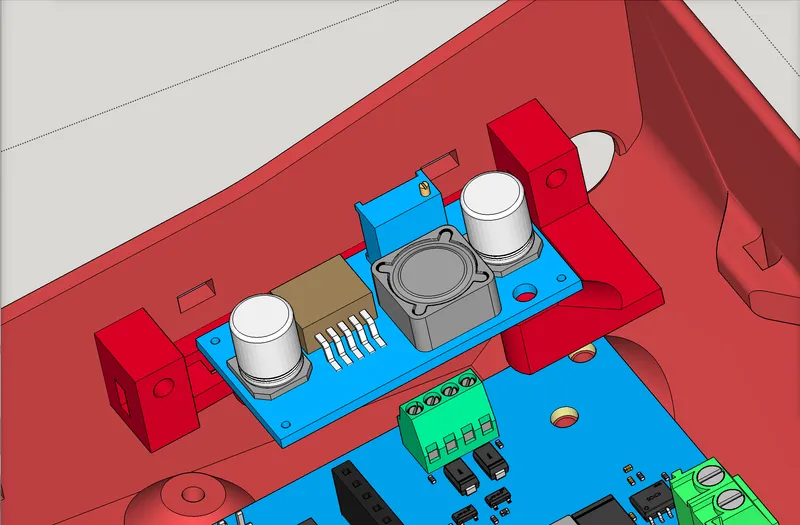
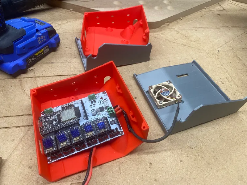
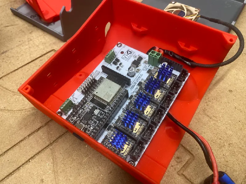
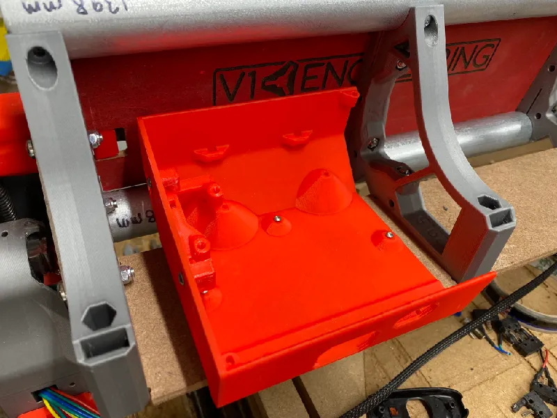
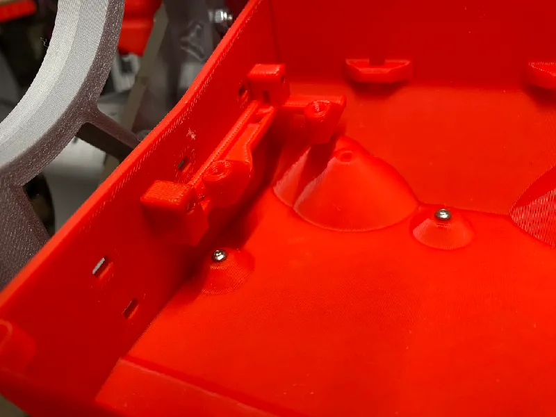
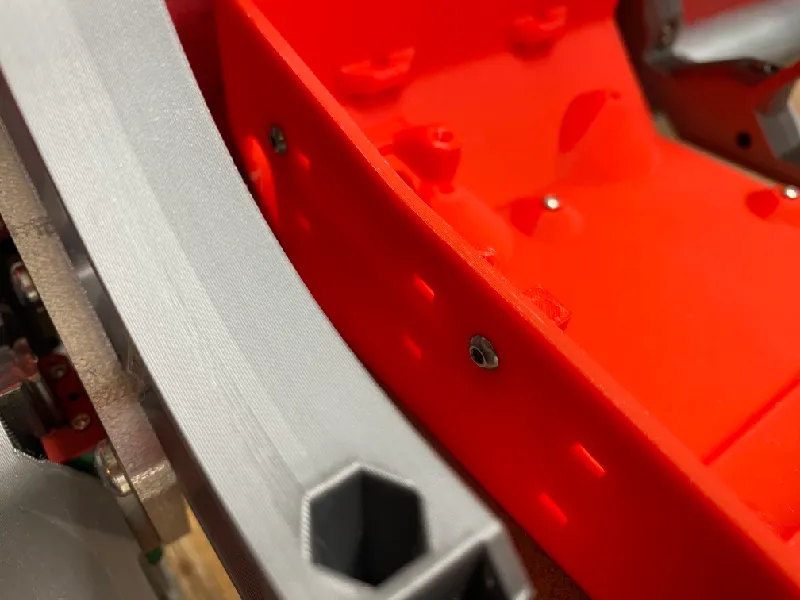
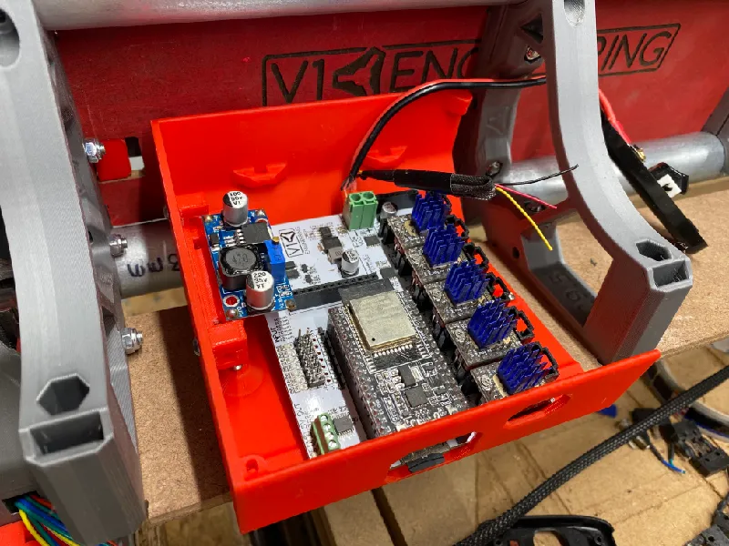
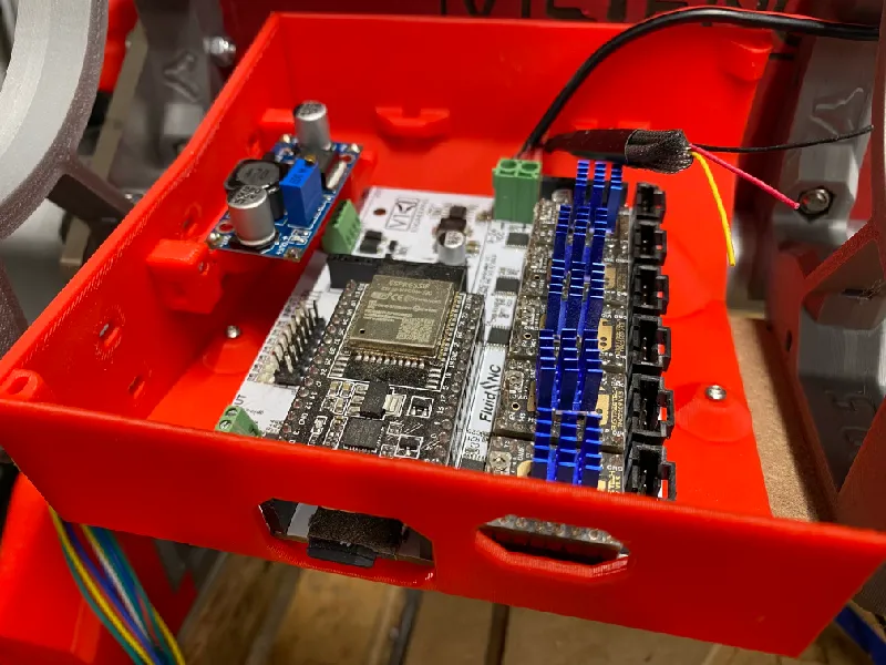
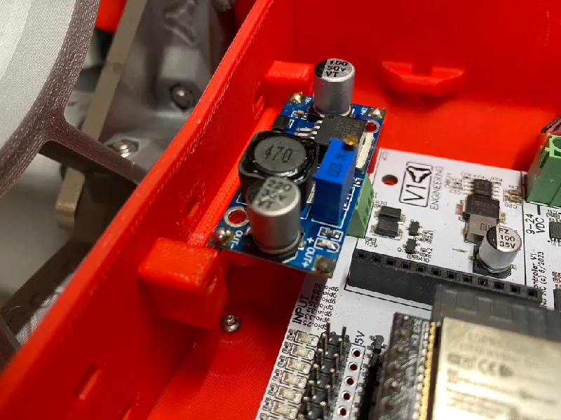
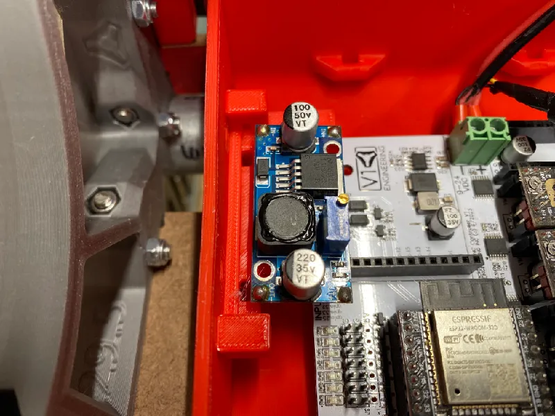
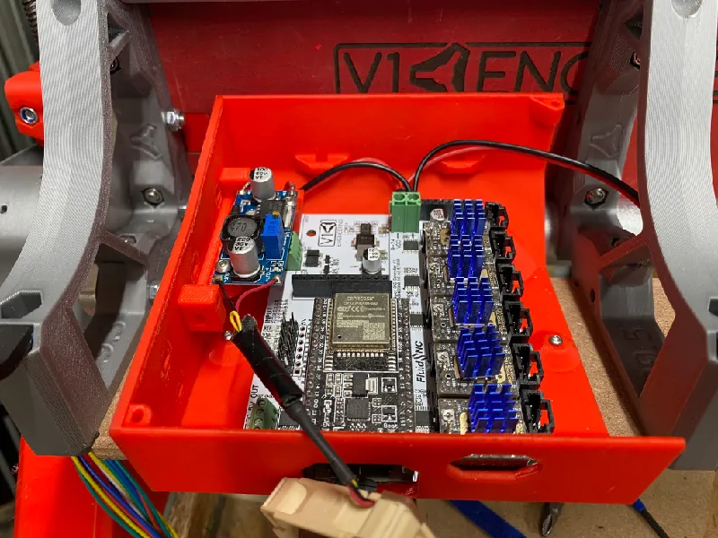
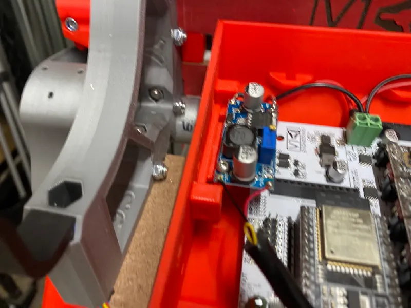
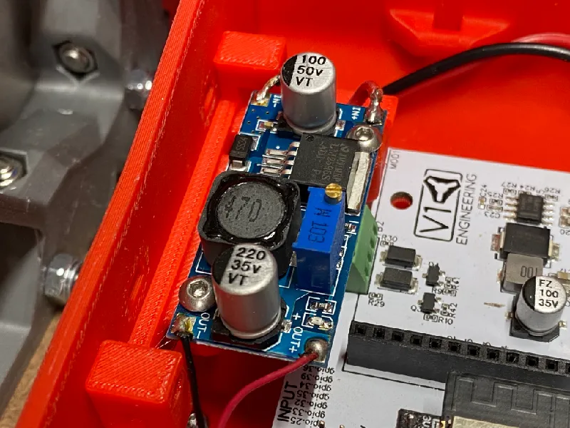
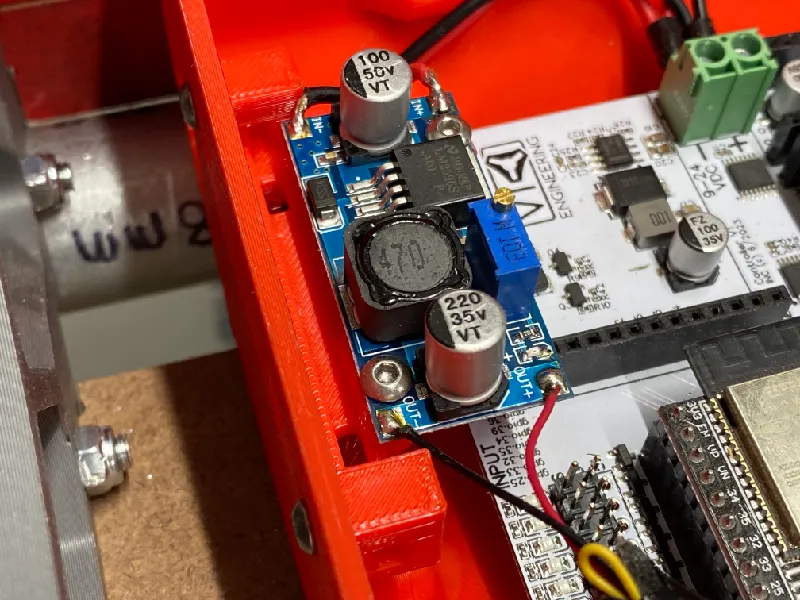
LowRider v4 CNC - Buck Converter Tray for Ryan’s V1E LR4 Jackpot Enclosure - can be attached w either zip ties or screws
Copy and paste from Description:
LowRider v4 CNC - Buck Converter Tray for Ryan’s (V1E) Jackpot CNC Control Box for the LowRider 4 CNC.
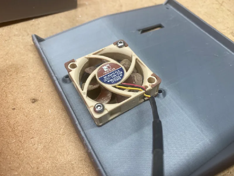
A buck converter can be used to provide 12v to a 12v fan, even if your power supply is 24v. It can also be used to under-volt LED lights to run them cooler and make them last longer.
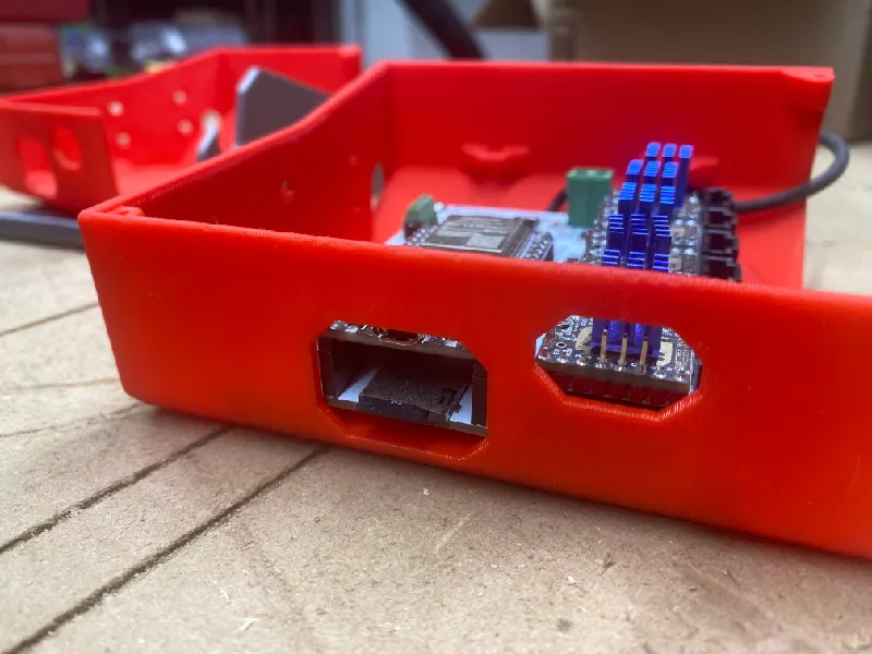
This tray can be attached with either zip ties or screws. If mounting with screws, use two M3 x 12 mm. No nuts needed. I drilled two holes in the left side of Ryan’s Jackpot enclosure using a 7/64" drill bit. I pre-marked the hole locations with a Sharpie, at about 14mm down from the top edge, and using the spacing of the top corners of the printed tray, since those corners are the same distance apart as the holes themselves. Below I illustrate these corners, but I marked and drilled from the outside of course.
My PayPal tip jar: https://paypal.me/design8studio
Various LowRider 4 CNC remixes:
View all my models and remixes on Printables:
*Amazon product links are affiliate links.
1 Like
I got my full size LR4 wired up and powered up and ran a first movement test. I re-used the wiring from before, which dates all the way back to LowRider v2 and v3. I’ve learned a lot since v2, and the wiring has some really sad points in it, compared to what I know how to do now. Re-using without at least double checking some weak connections, is coming back to bite me. One of the Z motors is not getting anything. As soon as I can gather up some motivation I will go over the wiring again.
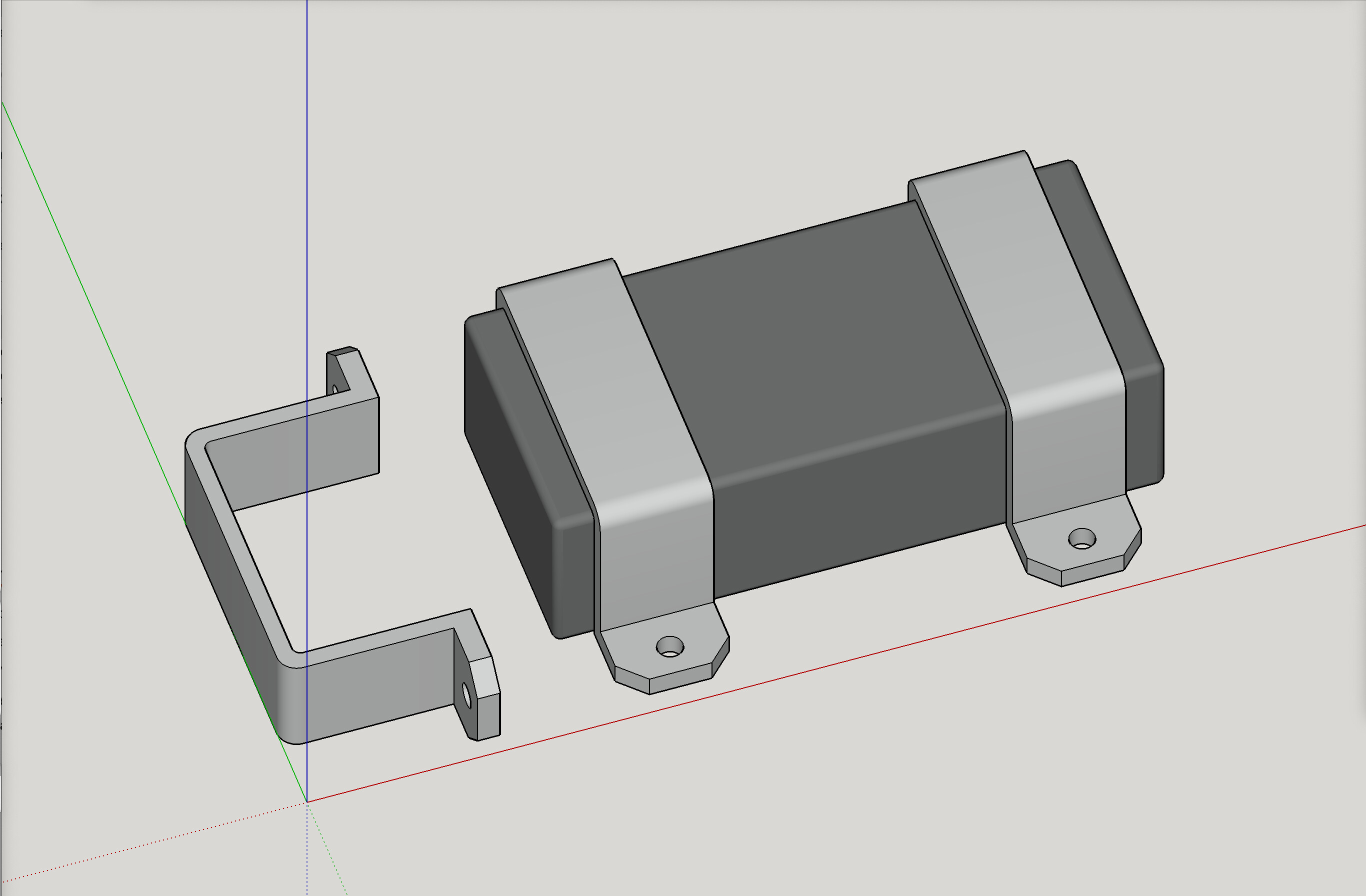
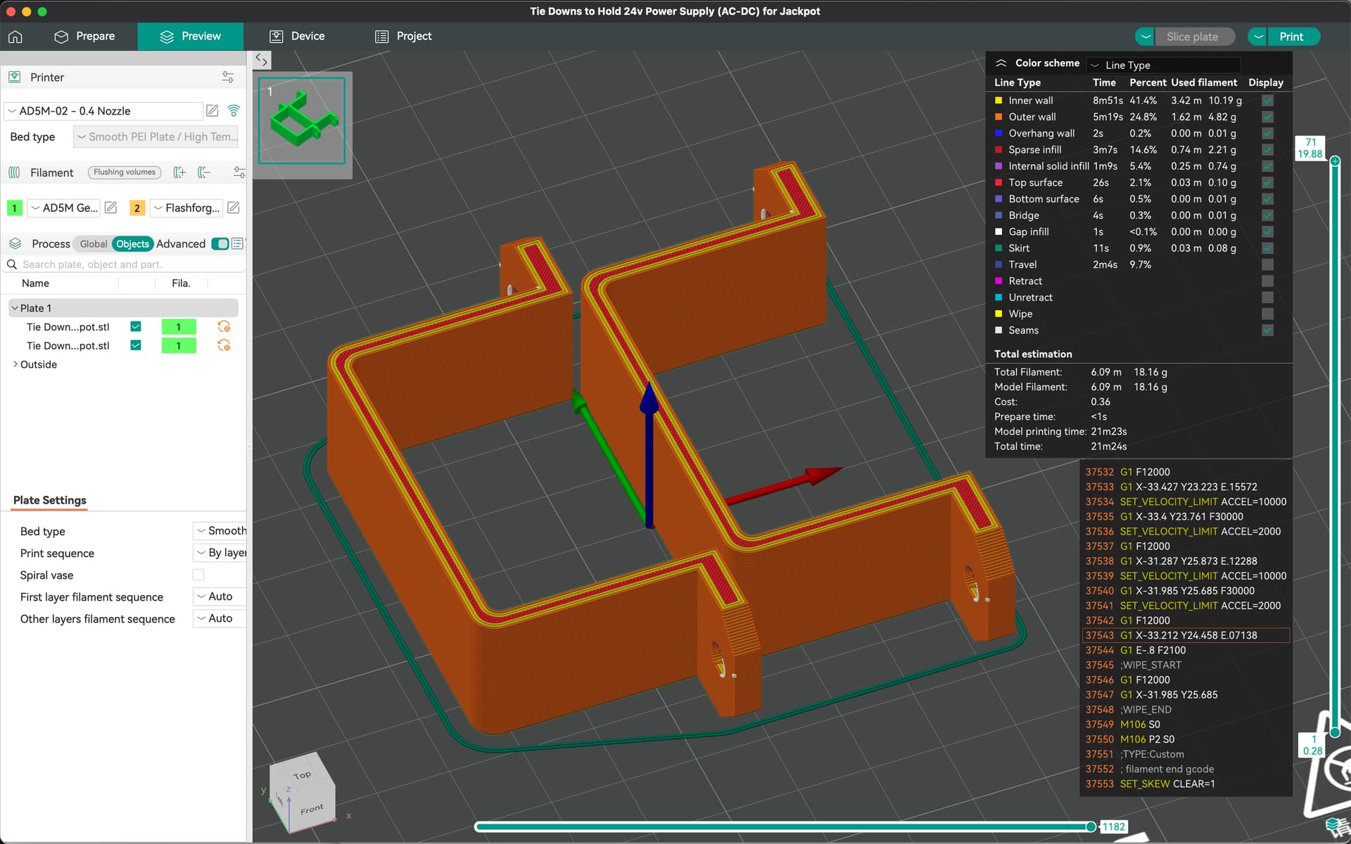
LowRider v4 CNC - Tie Downs to secure 24v Power Supply (AC-DC) to lower strut plate of gantry
LowRider v4 CNC - Tie Downs to secure 24v Power Supply (AC-DC) to lower strut plate of gantry
This is the 24v power supply I purchased from Ryan at v1e.com …
Print as oriented.
No supported needed.
I pre-drilled and used M3 screws, but only because I did not have the right size of small, self-tapping wood screw.

2 Likes